HANGCHA XC Series User manual

XC Series
Lithium Battery
Counterbalanced
Forklift Truck
CPD15/18-XD4-SI16
CPD20/25/30/35-XD4-SI21
CPD20/25/30/35-XD4-SI25
CPD20/25/30/35-XD4-SI26
CPD40/45/50-XD4-SI28
CPD50-XXD4-SI28
CPD15/18-XD6-SI16
CPD20/25/30/35-XD6-SI21
CPD20/25/30/35-XD6-SI26
CPD40/45/50-XD6-SI28
CPD50-XXD6-SI28
Operation and Maintenance Manual
Original Instruction
HANGCHA GROUP CO., LTD.
Dec. 2022

Foreword
Thank you very much for purchasing lithium battery counterbalanced forklift truck of Hangcha
Group.
Before using the truck, relative persons must read and understand the manual, get to know how to
safely operate and maintain the truck.
XC series four-wheel lithium battery counterbalanced forklift truck is a new product with small
turning radius, attractive design, compact structure, small size, low centre of gravity, good stability
and superior performance.
This manual is about the brief introduction and correct operation of the XC series four-wheel lithium
battery counterbalanced forklift truck, which will tell you how to operate safely and maintain
preventively. Relevant operator and maintainer must read this manual before operation.
Because of the update and improvements of our products, there may be some differences between
this operation manual contents and your forklift truck.
Please contact the sales company or agent of Hangcha Group in case of anything unclear.
This series of forklifts have passed CE certification.
Model
Traction
motor
controller
Pump motor
controller
Traction motor
Pump motor
Rated capacity (t) / Load
center (mm)
CPD15-XD4-SI16
ACS80M-
330C-35P
ACS80M-
330C-35P
XIPD150-130000-
000
XIPD150-621000-
G00
1.5/ 500
CPD18-XD4-SI16
1.8/ 500
CPD20-XD4-SI21
ACS80M-
330C-35P
ACS80M-
330C-23P
AIP252-130000-
000
XIPD352-621000-
000
2.0/ 500
CPD25-XD4-SI21
2.5 / 500
CPD30-XD4-SI21
ACS80L-
440C-35P
ACS80M-
330C-23P
3.0 / 500
CPD35-XD4-SI21
3.5 / 500
CPD20-XD4-SI25
ACS80L-
440C-35P
ACS80M-
330C-35P
JP308-130000-
000
JP452-622000-
G01
2.0/500
CPD20-XD4-SI26
XIPD351-130000-
000
CPD25-XD4-SI25
ACS80L-
440C-35P
ACS80M-
330C-35P
JP308-130000-
000
JP452-622000-
G01
2.5/500
CPD25-XD4-SI26
XIPD351-130000-
000
CPD30-XD4-SI25
ACS80XL-
550C-35P
ACS80L-
440C-35P
JP308-130000-
000
JP452-622000-
G01
3.0/500
CPD30-XD4-SI26
XIPD351-130000-
000
CPD35-XD4-SI25
ACS80XL-
550C-35P
ACS80L-
440C-35P
JP308-130000-
000
JP452-622000-
G01
3.5 /500
CPD35-XD4-SI26
XIPD351-130000-
000
CPD40-XD4-SI28
ACS80XL-
550C-35P
ACS80XL-
550C-35P
XIPD500-130000-
000
XIPD500-
621000-000
4.0 /500
CPD45-XD4-SI28
4.5/500
CPD50-XXD4-SI28
4.99/500
CPD50-XD4-SI28
5.0 /600

Model
Traction
motor
controller
Pump motor
controller
Traction motor
Pump motor
Rated capacity (t) / Load
center (mm)
CPD15-XD6-SI16
ACS80M3
5-C35T
ACS80M35
-C35T
XIPD150-130000-
000
XIPD150-
621000-G00
1.5/ 500
CPD18-XD6-SI16
1.8/ 500
CPD20-XD6-SI21
ACS80M3
5-C35T
ACS80M35
-C23T
AIP252-130000-
000
XIPD352-
621000-000
2.0/ 500
CPD25-XD6-SI21
2.5 / 500
CPD30-XD6-SI21
ACS80L50
-C35T
ACS80M35
-C23T
3.0 / 500
CPD35-XD6-SI21
3.5 / 500
CPD20-XD6-SI26
ACS80L50
-C35T
ACS80M35
-C23T
XIPD351-130000-
000
JP452-622000-
G01
2.0/ 500
CPD25-XD6-SI26
2.5 / 500
CPD30-XD6-SI26
ACS80L60
-C35T
ACS80M40
-C35T
3.0 / 500
CPD35-XD6-SI26
3.5 / 500
CPD40-XD6-SI28
ACS80L60
-C35T
ACS80L50-
C35T
XIPD500-130000-
000
XIPD500-
621000-000
4.0 /500
CPD45-XD6-SI28
4.5/500
CPD50-XXD6-SI28
4.99/500
CPD50-XD6-SI28
5.0 /600
Warning
In order to ensure the combination of the charging gun plug and the lithium battery socket, and
prevent the lithium battery gun from loosening during the charging process, the lithium battery
gun is provided with a lock, which cannot be pulled out even if it is pulled hard.So after charging,
the lock must be released. Only by pressing the button on the charging gun can the lock be
released and the charging gun can be pulled out smoothly.
To smoothly pull out the lithium battery charging gun, press the button on the gun. Or the gun
and socket will be damaged.
© Dec. 2022 HANGCHA GROUP CO., LTD

Content
1 TRUCK INTRODUCTION ...........................................................................................................1
1.1 SUMMARY...................................................................................................................................1
1.2 USE OCCASIONS AND CONDITIONS ...............................................................................................2
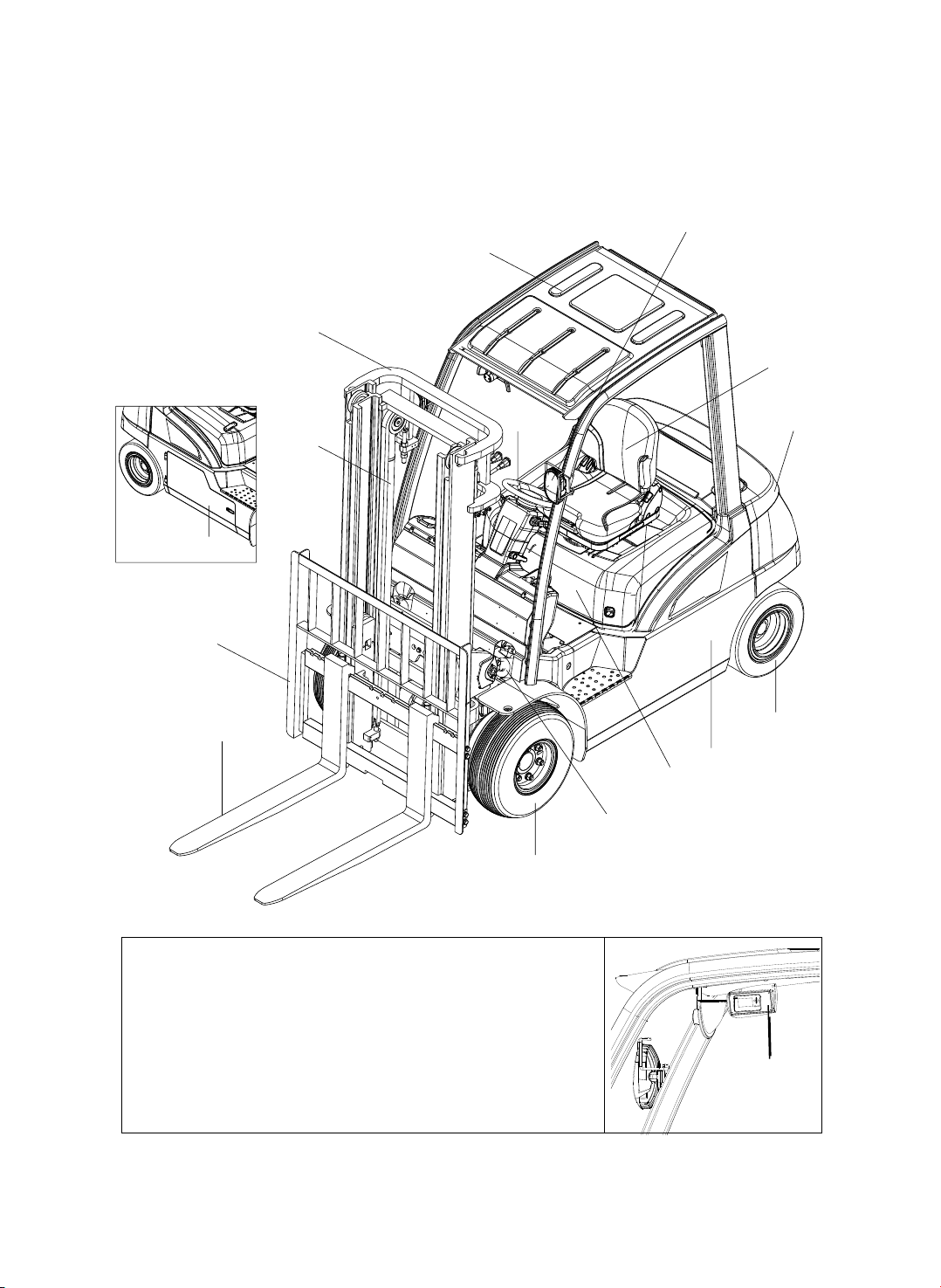
1.3 APPEARANCE AND MAIN PART......................................................................................................3
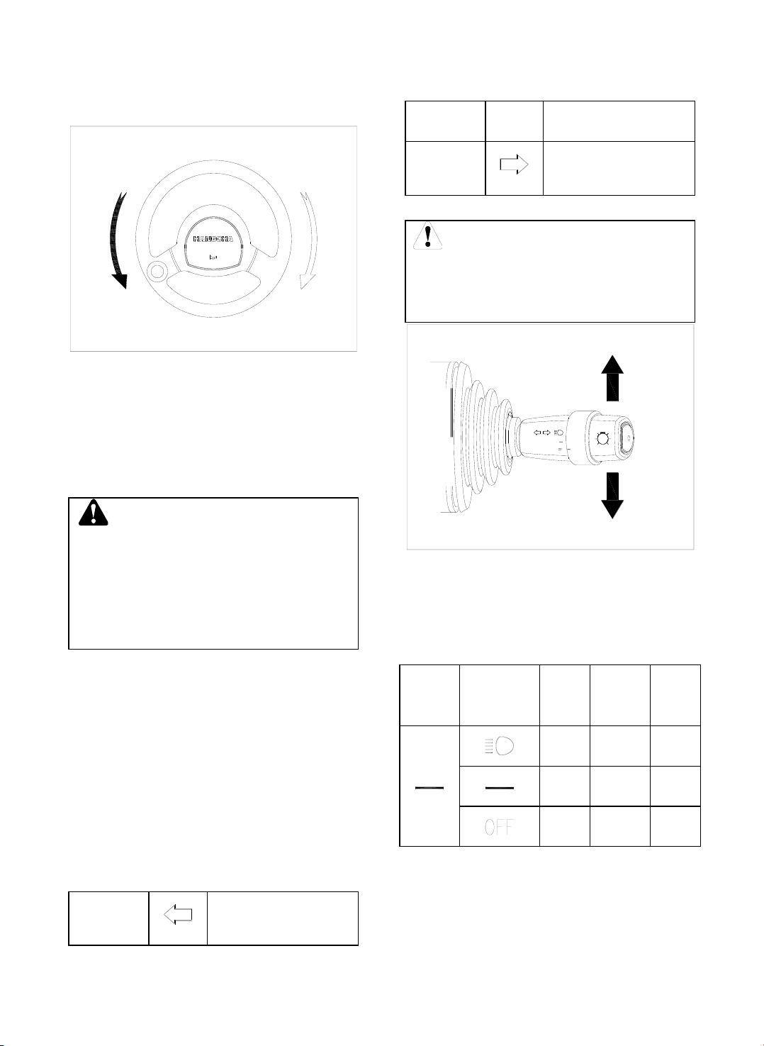
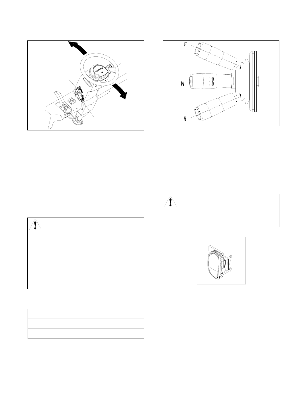
1.4 DISPLAYS AND CONTROLS ...........................................................................................................4
1.5 DISPLAY METER.........................................................................................................................13
1.6 LITHIUM BATTERY CHARGING PORT STRUCTURE AND ITS SIDE DOOR..............................................26
1.7 LITHIUM BATTERY REPLACEMENT AND INSTALLATION ....................................................................27
1.8 TRUCK BODY AND OTHERS...........................................................................................................28
1.9 ADJUST AND REPLACE FORKS ......................................................................................................33
1.10 OPERATOR PRESENCE SENSING (OPTION).................................................................................35
1.11 NAMEPLATE AND WARNING LABEL ..............................................................................................37
1.12 STRUCTURE AND STABILITY OF TRUCK........................................................................................39
2 SAFETY INSTRUCTIONS...........................................................................................................43
3 OPERATION AND SAFETY PRECAUTIONS FOR THE ELECTRIC FORKLIFT LITHIUM
BATTERY........................................................................................................................................50
4 TRUCK LIFTING, CARRYING AND TOWING ...........................................................................53
4.1 LIFTING.......................................................................................................................................53
4.2 CARRYING...................................................................................................................................55
4.3 TOWING ......................................................................................................................................56
5 LITHIUM BATTERY.....................................................................................................................57
5.1 SAFETY NOTICE...........................................................................................................................57
5.2 INSTALLATION INSTRUCTIONS.......................................................................................................57
5.3 BASIC TERMS OF LITHIUM-ION POWER BATTERY............................................................................58
5.4 USAGE NOTICE............................................................................................................................58
5.5 DAILY MAINTENANCE....................................................................................................................59
5.6 EMERGENCY PLAN.......................................................................................................................59
5.7 DIMENSION/WEIGHT ...................................................................................................................60
5.8 CHARGING OF LITHIUM BATTERIES................................................................................................61
6 OPERATING INSTRUCTIONS....................................................................................................75
6.1 DURING RUNNING-IN....................................................................................................................75
6.2 CHECK AND ADJUST BEFORE OPERATION..................................................................................75
6.3 OPERATION .............................................................................................................................81

7THE USE, INSTALL AND SAFETY RULES OF ATTACHMENT..........................................85
7.1 ATTACHMENT INSTALL..............................................................................................................85
7.2 ATTACHMENT USE....................................................................................................................85
7.3 ATTACHMENT CHECK AND MAINTENANCE..................................................................................86
8 RELATED SAFETY INSTRUCTION AND STANDARD (FOR TRUCKS EXPORTING TO
EUROPE OR OPTION)...................................................................................................................87

1
1 Truck introduction
1.1 Summary
Truck body
–Lateral battery extraction frame. The lithium battery sinks to the bottom of the frame. The
length of the whole vehicle is shorter (80-100mm shorter than ordinary vehicles).
Drive and brake system
–Integrated drive axle
–High-efficiency and high-power AC drive motor provides super driving force, and the
driving speed can reach 18km/h.
Control system
–Ergonomic, large operating space
Hydraulic system
-Adoptedhigh-poweroilpumpmotorandworkingoil pumpgreatlyimprovestheliftingspeed.
Electrical system
–80V battery pack provides super power. Lithium battery adopts Ningde Era battery cell.
–Large-size color screen instrument, standard cloud intelligent management module.
–International advanced communication control system
Steering system
Angle sensor
The driving speed is about 18km/h, the lifting speed is about 540mm/s, and the performance is in
line with the X series internal combustion vehicles of the same tonnage.

2
1.2 Use occasions and conditions
The forklifts described in this manual are only suitable for loading and unloading and transporting
goods over short distances.
It must be used, operated and maintained according to the information in this manual. Any other
uses are outside the design envelope and can lead to injury to persons or damage to equipment or
property.
Only used in specified place and condition:
–Use in specified rated load.
–Used in specified area as factory, tourist attraction and recreation place.
–Used on the flat ground, that is fixed and owns enough carrying capacity.
–Used on the road with good vision and equipment use license.
–Approved working site temperature is -5℃~40℃.
–Altitude should not over 2000m.
–Max. gradability when driving with full load is 18%. It is prohibited to travel crosswise or
obliquely when going uphill. When going uphill with loads, keep the loads in front; when
going downhill, keep people in front.
Please read other safety rules in this manual, it is important to your personal safety, working staff
and goods safety.
Warning
⚫It is forbidden to drive outside the designated areas such as highways.
⚫Overloading and illegally carrying people are strictly prohibited.
⚫Do not push or pull loads.
⚫Non-explosion-proof forklifts areforbidden tobe usedin flammable and explosive places.
⚫If it is not a cold storage type, it is forbidden to use it in a cold storage.

3
1.3 Appearance and main part
1. Fork 2. Load bracket 3. Inner mast 4. Outer mast
5. Steering wheel 6. Overhead guard 7. Counterweight 8.
Seat
9. Rear wheel (steering wheel) 10. Frame 11. Hood
12. Tilting cylinder 13. Front wheel (drive wheel)
14. Lithium battery side door 15. Meter 16. Headlight
`
14
16
1
2
12
4
3
6
8
11
7
9
10
13
5
15

4
1.4 Displays and controls
1. Steering wheel
2. Horn 3. Combination light switch 4. Key switch 5. Lift lever
6. Tilt lever 7. Cup holder 8. Emergency stop button 9. Rocker switch 10. Accelerator pedal
11. Brake pedal 12. Hand brake handle 13. Steering wheel adjustment switch 14. Forward and
backward switch
1236
5
47
8
9
11 10
13
12
14

5
Steering wheel [1]
Control the truck direction.
When the steering wheel is turned right, the
forklift will turn to the right; when the steering
wheel is turned left, the forklift will turn to the
left. The rear end of the forklift swings out
when turning.
Warning
This forklift truck adopts a fully hydraulic
steering system. Therefore, steering will
be impaired when the oil pump motor
stops running. Immediately restart the oil
pump motor before turning again.
Horn button [2]
Press the horn button in the center of the
steering wheel and the horn will sound.
Combination lights [3]
The combination lights include turn signal lights
and light switch.
Turn signal: Push or pull this switch, the
corresponding left and right turn signal light
flash.
Push
Forward
Left turn light
flashes
Neutral
Off
Pull back
Right turn light
flashes
Caution
Steering lamp switch can not return to
neutral position automatically, and should
reset manually.
Light switch:Rotation type switch. Control
the light through the knob on the head of
combination switch.
×:Indicates that it is connected
Contact
symbol
Light
symbol
Front
lamp
Head
lamp
Width
lamp
×
×
×
×
右转左转

6
To turn on the headlights, front signal lights,
and width lamps, turn the switch to align the
position line on the switch handle with the
corresponding mark on the switch body.
Key switch [4]
Switch on and off the control current. Remove
the key and make sure that the truck does not
move suddenly.
Thekeyswitchhastwopositions:ONandOFF.
First set the direction lever to the neutral
position, release the accelerator pedal, and
then turn the key clockwise to the ON position.
Caution
⚫If the direction lever is not in neutral
ortheacceleratorpedalisdepressed,
the forklift will not start when the key
switch is turned to ON.
⚫At this point a fault code will be
displayed, which is perfectly normal.
⚫Return the direction lever to the
neutral position and take your foot off
the accelerator pedal before
attempting to start the forklift.
⚫The fault code will then disappear.
Lift lever [5]
Control the forks’ up or down.
Push——down; pull——up
Lifting speed can be controlled by tilt
backwards angle of lever and accelerator pedal,
the lowering speed can be controlled by tilt
forwards angle of the lever.
Tilt lever [6]
It is used for forward and backward tilting of the
mast.
Push——tilt forward;
Pull——tilt backward
The tilting speed is controlled by tilting angle of
the lever and accelerator pedal effort.
Caution

7
The multi-way valve is equipped with a
front tilt self-locking valve. When the
circuit is cut off, the mast cannot tilt
forward even if the lever is pushed
forward.
Sideshifter lever
It’s used for left shift and right shift of sideshifter
bracket
Push——Left shift Pull——Right shift
The side shifting speed is controlled by the tilt
angle of the lever and accelerator control.
Attachment lever
It can be a sideshift control lever, or a rotary
control lever or other attachment control lever,
depending on the specific situation.
Cup holder [7]
It is in the right side of the instrument stand for
driver placing the cup.
Emergency stop button [8]
Turn the power on or off.
In case of emergency, press the red mushroom
button to cut off the main power of the vehicle.
No walking, turning, lifting.
Caution
Do not use the emergency stop switch to
stop the truck under normal
circumstances as the key switch.
Rocker switch [9] [optional]
The rocker switch is the warning light and the
rear headlight, the left is the warning light and
the right is the rear headlight.
1 Alarm light switch: press down, the alarm
light flashes; press up, the alarm light goes out.
2 Rear headlight switch: press down, the rear
headlight is on; press up, the rear headlight is
off.
Symbol
Control element
Warning Light
Rear headlight
Caution
Whether this lightis on or off has nothing to
do with the position of the key switch, so do
not forget to turn off the light.
Accelerator pedal [10]

8
Stepless regulation for the driving speed of the
forklift.
Slowly depress the accelerator pedal, the drive
motor will start running and the forklift will move
off. According to the pedaling force on the
pedal, the running speed can be adjusted
steplessly.
Caution
Release the accelerator pedal while
driving to perform soft braking.
Warning
Do not depress the accelerator pedal
before turning on the key switch,
otherwise the meter will display a fault.
Release the accelerator pedal, the fault
will disappear.
Brake pedal [11]
Depressing the brake pedal will slow down or
stop the forklift. Release the pedal and the
vehicle runs.
Caution
Avoid sudden braking. Sudden braking
can easily cause the vehicle to overturn or
the cargo to fall, resulting in a safety
accident.
Hand brake lever [12]
Pull the handle back to tighten it; push the
handle forward to loosen it. The handle must
be pulled tight before the operator leaves the
forklift.
Caution
In case of brake system doesn’t work or
emergency occurs, you can tighten this
lever to stop the truck urgently. Usually, it is
strictly forbidden to use the handbrake to
achieve service braking.
Steering wheel tilt lever[13]

9
Position of steering wheel is adjustable. Pull up
the lever on the left side of direction column,
and adjust the steel wheel to the desired
position, and then push down the lever to lock.
Caution
a. Only after stopping the truck and
pulling up the hand brake lever can you
adjust the tilting angle of steering wheel.
b. After adjustment, turn the steering
wheel up and down firmly to make sure it is
locked.
Reversing lever [14]
It is installed on the left of the steering column.
F
Forward
N
Neutral
R
Reverse
Before changing the direction of travel, depress
the brake pedal to bring the vehicle to a
complete stop, then shift the handle forward to
a forward gear. If you need to go backwards,
depress the brake pedal to slow down the
speed of the vehicle, move the handle
backwards to a reverse gear.
Caution
The forklift can only be started when the
lever is in the neutral position.
Headlights[16]
When the lighting conditions of the working
environment do not meet the requirements, it is
required to turn on the headlights
Fingertip operation(option)
Armrest system is composed of armrest
bracket, fingertip, emergency stop button, horn
button and wire etc.
Lock
Release

10
1. Direction
switch
2. Horn button
3. Lift switch
4. Tilt switch
5. Sideshift
switch
6 Attachment
switch
7. Emergency
stop button
8.Level shift
handle
9. Vertical shift
handle
Direction switch
Set forklift direction according to need.
Direction switch is used to switch the forklift
going forward or backward. Press the switch
forwardand stepontheacceleratorpedal,forklift
travels forward; press the switch backward,
forklift travels back.
Caution
⚫If press the direction switch to opposite
direction during truck running, the
electric braking works to decelerate the
forklift. After stop, the truck moves to
another direction.
⚫If the direction lever is not in neutral,
whenthekey switchis turned on,afault
code will be displayed. Return the
direction lever to the neutral position,
the fault code will then disappear.
Lift switch
Push the switch forward to lower the fork; pull
the switch backward to lift the fork. The lifting
and lowering speed is controlled by the tilt
angle of the switch, the larger the angle, the
faster the speed.
Tilt switch
1
2345
7
6
8
9

11
Push the switch forward to tilt the fork forward;
pull the switch backward to tilt the fork
backward; The tilting speed is controlled by the
tilt angle of the switch.
Caution
⚫The multi-way valve is equipped with a
front tilt self-locking valve. When the
circuit is cut off, the mast cannot tilt
forward even if the lever is pushed
forward.
Sideshift switch
Move the switch back and forth to make the
fork move left and right relative to the mast.
Attachment switch
Apply when installing the attachment with the
fourth valve. Push and pull this switch can
realise the attachment function.
Horn button
Press this button when a reminder or warning
audible signal is required.
Emergency stop button
In an emergency, press the button to cut off the
vehicle's main power supply.
Caution
⚫Do not use the emergency stop switch
to stop the truck under normal
circumstances as the key switch.
Level shift handle
Adjust horizontal position of armrest:Turn
upward, release the armrest and move it to
proper position; turn downward, lock the
armrest.
Vertical shift handle

12
Adjust armrest height: Turn upward,
release the armrest and vertically move it
to proper position; turn downward, lock the
armrest.

13
1.5 Display meter
1.5.1 Multifunction display screen
Located in the top right corner of the overhead guard.

14
No.
Display
No.
Display
A
Current battery capacity
H
Body control shortcut menu
B
Whether the vehicle is in a forward or
reverse state, it is not displayed when
in neutral
I
Handbrake light: Lights up when the
driver operates the handbrake
C
Current three working modes: "S", "P",
"E"
J
Seat light: Lights up when the driver
leaves the seat
D
Current vehicle speed in km/h or MPH
K
Lift lock light: When the battery is lower
than or equal to 10%, the lift lock light
is on
E
The arrows represent the direction in
which the steering wheel travels
L
Battery light: Lights up when the
battery level is lower than or equal to
20%
F
Menu
M
Neutral light: Lights up when the
vehicle is in neutral
G
The number shows the current
cumulative working time of the vehicle,
and the 5-digit display shows that after
the key switch is connected to the
power supply, the vehicle starts to
work, and the working timer starts to
count.
N
Turtle speed lights
Menu
Icon
Name
Function
Up
Move the cursor up, orincrease the selected number by 1; switch
S mode (turtle speed mode) in the main interface;
Left
Move the cursor to the left; switch the P mode in the main
interface;
Right
Move the cursor to the right; switch the E mode in the main
interface;
Down
Move the cursor down, or decrease the selected number by 1;
取
Cancel
Cancel the current content or return to the previous menu;

15
Enter
Confirm the current operation, enter the menu mode in the main
interface;
Body control shortcuts
Icon
Name
Function
Function
key 1
Drive external relays, the specific functions are based on on-site
usage
Function
key 2
Function
key 3
Function
key 4
Function
key 5
Combination key
Icon
Name
Function
Up
In the main interface, press the "up " and "down " at the same
time to view the instrument information, including the instrument
number, SIM card number and software version number;
Down
Menu structure introduction
Menu
Description
Remark
1.
Switch monitor
--------------------------------------------------------(
operator, administrator
)
Monitoring
value, cannot be changed
SW
MONITOR
1
Seat switch
Seat switch status
This manual suits for next models
32
Table of contents
Other HANGCHA Forklift manuals

HANGCHA
HANGCHA CBD20-AMC1 Installation guide

HANGCHA
HANGCHA XF Series User manual

HANGCHA
HANGCHA R Series User manual

HANGCHA
HANGCHA XE Series User manual

HANGCHA
HANGCHA CBD15-A2MC1 User manual

HANGCHA
HANGCHA XF Series Quick start guide

HANGCHA
HANGCHA J Series User manual

HANGCHA
HANGCHA CPCD30/35-XW43E-RT Quick start guide

HANGCHA
HANGCHA CPD10-A User manual