HANGCHA CPCD30/35-XW43E-RT Quick start guide

I
OPERATION MANUAL
2.5-3.5T Rough terrain forklift truck
Operational and Maintenance Manual
Original Instruction
CPCD30/35-XW43E-RT
CPCD25-XW43E-RT
CPCD30/35-XW33E-RT
CPCD25-XW33E-RT
CPCD30/35-XW33C-RT4
CPCD25-XW33C-RT4
CPCD30/35-XW43C-RT4
CPCD25-XW43C-RT4
CPCD30/35-XW98C-RT4
CPCD30/35-XW98E-RT2
CPCD25-XW98C-RT4
CPCD25-XW98E-RT2
HANGCHA GROUP CO., LTD
12/2019

II
Foreword
2.5-3.5T Rough terrain forklift truck is a new developed forklift of Hangcha Group.
It owns characteristics as High vehicle capacity, novel structure and superior
performance. This manual introduces safety, operation, transportation, lubrication, brief
structure and maintenance method of trucks. Driver, maintenance personnel and
equipment manager must read and comprehend this manual before use.
Because of the update and improvements of our products, there may be some differences
between this operation manual contents and your forklift truck.
Illustration adopted by this manual may vary from your truck structure.
This manual is also available for container forklift and forklift equipped with attachment.
Please contact Hangcha Group or your sales agent if you have any questions regarding
this manual. Standard model
Load center mm(in)
500(19.7)
Model
CPCD15-
CPCD18-
CPCD20-
CPCD25-
CPCD30-
Rated capacity kg( lb)
1500(3300)
1750(3850)
2000(4400)
2500(5500)
3000(6600)
Model
CPCD35-
CPCD40-
CPCD45-
CPCD50-
CPCD55-
Rated capacity kg( lb)
3500(7700)
4000(8800)
4500(10000)
5000(11000)
5500(12000)
Load center mm(in)
600(23.6)
Model
CPCD15-
CPCD18-
CPCD20-
CPCD25-
CPCD30-
Rated capacity kg( lb)
1350 (3000)
1600(3500)
1800(4000)
2250(5000)
2700(6000)
Model
CPCD35-
CPCD40-
CPCD45-
CPCD50-
CPCD55-
Rated capacity kg( lb)
3200(7000)
3650(8000)
4000(9000)
4500(10000)
5000(11000)

III
CE model: optional maximum lifting height 6000 mm
Careful
Bearing capacity chart
This chart shows the
relationship between the location
of the load center distance and the
maximum load. Before loading,
check whether the load and load
center distance are within the
allowable range of bearing
capacity chart. If the shape of the
load is complex, place the heaviest
part of the load in the center of the
fork and close to the shelf.
Note; The vehicle tonnage value shown below is based on the load center distance of
500mm.
Model
Engine
Hydraulic
transmission
Load
center(mm)
CPCD30/35-XW43E-RT
Cummins
QSF2.8T3NA49
Diesel engine
RTE350-120000-G00
CPCD25-XW43E-RT
RTE250-120000-G00
CPCD30/35-XW43C-RT4
RTE350-120000-G00
CPCD25-XW43C-RT4
RTE250-120000-G00
CPCD30/35-XW33E-RT
4TNE98-BQFLC
Diesel engine
RTE350-120000-G00
CPCD25-XW33E-RT
RTE250-120000-G00
CPCD30/35-XW33C-RT4
RTE350-120000-G00
CPCD25-XW33C-RT4
RTE250-120000-G00
CPCD30/35-XW98C-RT4
Kubota
V2607-CR-TE5
B
Diesel engine
RTC350-120000-G00
CPCD30/35-XW98E-RT2
RTE350-120000-G00
CPCD25-XW98C-RT4
RTC350-120000-G00
CPCD25-XW98E-RT2
RTE250-120000-G00
©11/2019 HANGCHA GROUP CO., LTD
Actual LiftingCapacity
mm
Mast Model
RATEDCAPACITIESANDLOADGENTRESGRAPH
LoadCenter DistanceB CapacityWithMast Vertical
mm
kg
Attachment Model
Max.Lift Height A Serial No.
RT
FORINDUSTRIALUSE- ACCORDINGTOSTANDARDISO22915-2
FORROUGHTERRAINUSE- ACCORDINGTOSTANDARDISO22915-13
kg

IV
Content
Content .................................................................................................................IV
I. General rules ......................................................................................................1
II. Name of main parts or component.....................................................................3
1. Instruments.................................................................................................4
CAN Bus Instrument(W98) ........................................................................... 11
2. Controls and switches...............................................................................17
3. Truck body and others ..............................................................................23
III. Safety rules.....................................................................................................28
IV. Maintenance...................................................................................................34
1. Daily maintenance(8hours)..................................................................34
2. Weekly maintenance(40hours).............................................................37
3.Every One and a half months ....................................................................41
4.Every half year maintenance (1000 hours) ................................................44
5.Annual maintenance (2000 hours).............................................................46
6.Others........................................................................................................47
V. Structure and stability of truck .........................................................................50
VI. Operation........................................................................................................52
VII. Parking ..........................................................................................................55
VIII. Maintenance.................................................................................................57
1. Preventive maintenance schedule............................................................57
2. Torque Specifications................................................................................66
3. Periodic replacement of key safe parts.....................................................67
4. Table for the oil used in the truck ..............................................................68
5. Lubrication system drawing ......................................................................70
IX. Labels:Stick various nameplate and mark at different position of the truck..71
X. Truck transporting, lifting, towing.....................................................................76
XI. Main technical performance parameter ..........................................................77
XII. Operational method of lead acid battery........................................................89
XIII. Use, installation and safety rules of attachment ...........................................92
XIV. Description of OPS System..........................................................................94
XV. Relevant safety command and standard.......................................................96
XVI.Maintenance record.......................................................................................98

1
I. General rules
To keep the truck and you safe, obey these rules below:
1. Only trained and authorized operators shall be permitted to operate the truck.
2. Before starting truck you should check all control and alarm devices; if any are damaged, DO
NOT operate until it is repaired.
3. When carrying a load, do not overload. The forks should insert in the load completely and evenly.
It is not permitted use only one fork to load.
4. You should operate the truck smoothly when starting, turning, traveling, braking and parking. On
a slick or wet road, decrease speed when turning.
5. Lower the forks and tilt the mast backwards when traveling with a load.
6. If the slope angle is bigger than 10%, travel forward up slope and backward down slope. Never
turn sideways or stack load on an incline.
7. Be aware of bystanders, barriers, potholes and overhead clearances.
8. DO NOT allow passengers or persons to stand on the fork.
9. DO NOT stand or walk under the fork.
10. DO NOT operate the truck or attachment from any position except the operator‘s seat.
11. DO NOT carry the load unpackaged. Be careful when carrying large loads.
12. Take care not to lose load when lift height is higher than 3 meters, take protective measures if
necessary.
13. Travel with load as low as possible and tilt back the mast.
14. When driving over a dock-board or bridge-plate, be careful and drive slowly.
15. Make sure that there is no naked flame near the area, never smoke. The driver should not
remain seated when adding fuel.
16. Treat the truck with attachments as a loaded truck
17. When leave the truck, you should put the forks down, make the shift lever in neutral, shut down
the engine and cut the power. When parking on a grade, make sure to tighten the brake lever. If
necessary, use a block when parking on a grade for a long time.
18. If the truck suddenly gets out of order, or for leakage of electrolyte, hydraulic oil or brake oil
when lifting goods or grade climbing, leave truck in safe state and contact service technician
immediately.
19. During installation and assembly, there will be noise and vibration. Please choose the right tool
and assembly method. Minimize the noise and vibration as soon as possible to reduce noise
pollution.
20.Rough Terrain forklift Truck mainly used in the field of urban engineering construction sites, pipe
laying, field development, operations, and other mountain forest, and loading and unloading
operations forces used the army as well as loading and unloading dock yard containers.
21. Move the truck to the place where respects traffic when it anchors. If the reason is brake or turn
system, move it by a suitable truck (Refer to the part of truck carrying); other reasons, use a
suitable truck to move, tie the cord outside of truck. Please abide by the traffic regulations when
moving the truck on roads.
22. DO NOT operate the truck or load cargo after removing the hood, water tank cover board,
overhead guard, or load backrest of mast.
23. Make sure there is enough light around the work area. At night, use the head lamps.
24. Handle with automatic pitch fork of the forklift when the load must not make lateral operation, so
as not to lose balance and forklift components of the damage caused.
25. Before hydraulic oil temperature rises, do not tilt the mast forward, backward or lift the mast to
the limit when in idling.
26. No modifications or alterations to a powered industrial truck, which could affect, for example,
capacity, stability or safety requirements of the truck, shall be made without the prior written
approval of the original truck manufacturer, its authorized representative, or a successor thereof.
This includes changes affecting, for example, braking, steering, visibility and the addition of
removable attachments. When the manufacturer or his successor approves a modification or
alteration, the manufacturer or successor shall also make and approve appropriate changes to

2
the capacity plate, decals, tags and operation and maintenance handbooks.
27. In the event the truck manufacturer is no longer in business and there is no successor in the
interest to the business, the user may arrange for a modification or alteration to a powered
industrial truck manufacturer and the user shall:
(1) Arrange for the modification or alteration to be designed, tested and implemented by an
engineer(s) expert in industrial trucks and their safety;
(2) Maintain a permanent record of the design, test(s) and implementation of the modification or
alteration;
(3) Approve and make appropriate changes to the capacity plate(s),decals, tags and instruction
handbook;
(4) Affix a permanent and readily visible label to the truck stating the manner in which the truck
has been modified or altered together with the date of the modification or alteration, and the
name and address of the organization that made the modification or alteration.

3
II. Name of main parts or component
1. Fork
2. Load backrest
3. Tilt cylinder
4.Mast
5.Lift cylinder
6. Steering wheel
7. Overhead guard
8. Seat
9. Cover hood
10. Counterbalance weight
11. Rear wheel
12. Truck frame
13. Front wheel
4
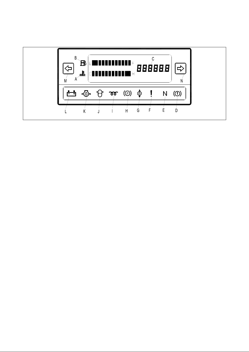
1. Instruments
(Two-wheel drive rough terrain forklift truck)
A.Water temperature gauge
B.Fuel gauge
C.Timer
D.Accumulator warning indicator
E. Neutral position start-up
indicator
F. OPS indicator
G.Transmission oil temperature
warning light
H. Parking indicator
I. Preheat indicator light
J. Oil water seperator Indicator light
K.Engine oil pressure warning light
L. Charging indicator light
M. Left turning indicator
N. Right turning indicator

5
Instrument of the state shown in Figure
Water temperature gauge [A]
This gauge indicates the oil temperature in
the torque converter transmission box when
the key is at ┃(ON) position. In normal status,
LED Displayed in the range of 40 ℃-110 ℃
Caution
If LCD display in the red zone , please stop the
truck at once. Decrease the engine speed to
make the engine cool. Check the cooling fluid if
enough and the fan belt‘s elasticity if fit.
Fuel gauge [B]
The gauge indicates the fuel level in the tank
when the key is at ┃(ON) position.
Suggest filling up the fuel tank after work
every day.
6
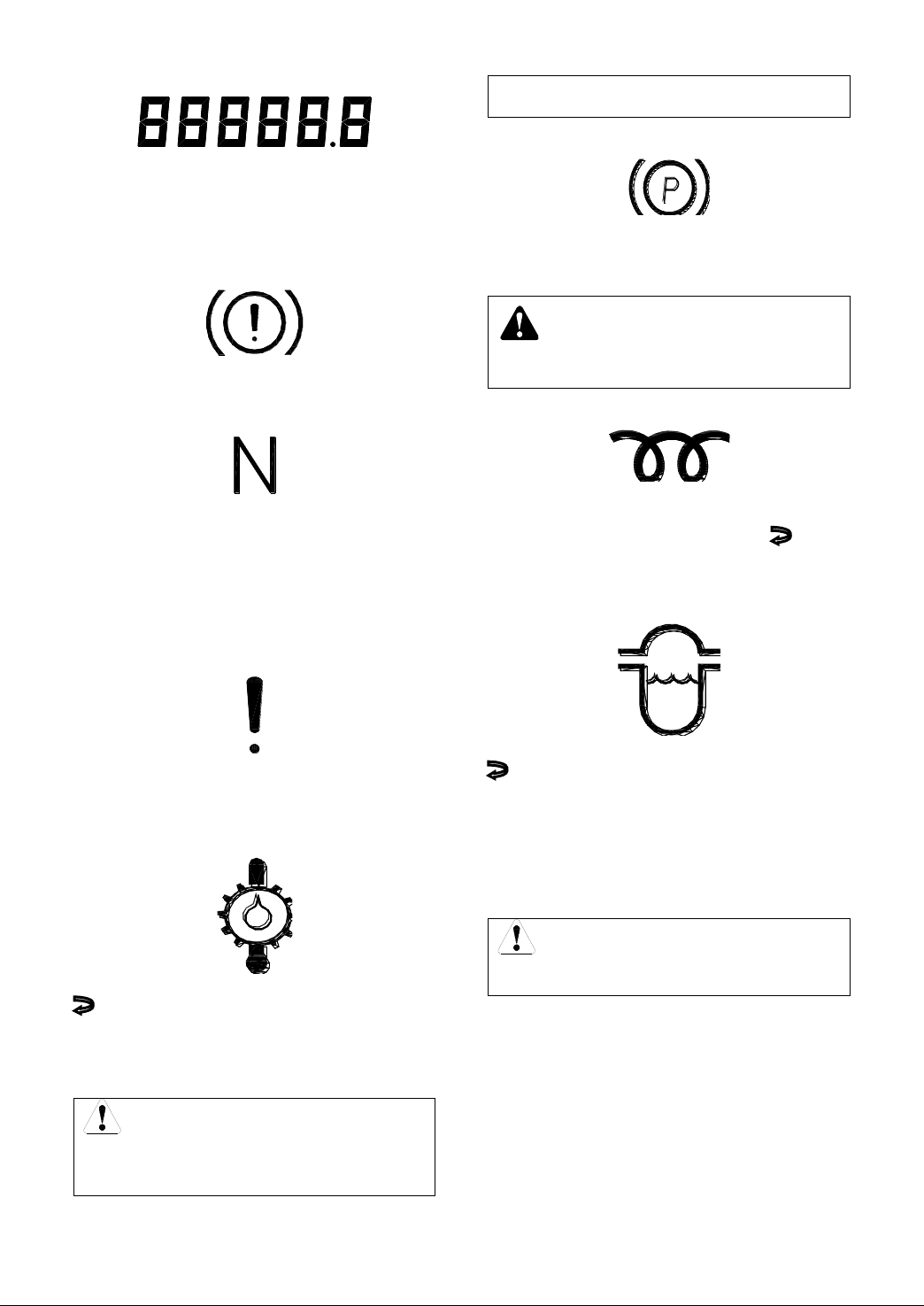
Hour meter [C]
This meter measures working time of engine
when the key is at ┃(ON) position. The meter
increase one number every working hour.
Use meter to schedule lubrication and
maintenance periods.
Accumulator warning indicator [D]
This indicator light does not work on the
forklift.
Neutral position start-up indicator [E]
Put the steering handle in the neutral position
when truck on the temporarily stop, the light
will indicated on
The truck can be started up only in the neutral
position.
It‘s prohibited for truck in the neutral position
sliping when it‘s on the slope.
OPS indicator [F]
When this light is on, it means driver leave the
seats or not sitting on the seat correctly.
Transmission oil temperature warning
light [G] (Hydraulic Forklift)
In normal state, once the starter is set to
―ON‖ position, this lamp lights up. After the
engine is started up, it goes out.
During work time if the oil temperature exceed
the normal rang(60~120。C) the indicator light
on.
Caution
If the pointer enters the red range, stop the
operation instantly and slow down engine
speed to cool the coolant and wait until the
pointer goes into the green range, and have
a check then.
Parking indicator [H]
Parking indicator shows on means brake is
affected, Please loosen the parking handle
(hand brake handle), the parking indicator will
shows off.
Warning
It will damage the engine and
transmission, etc. when indicated.
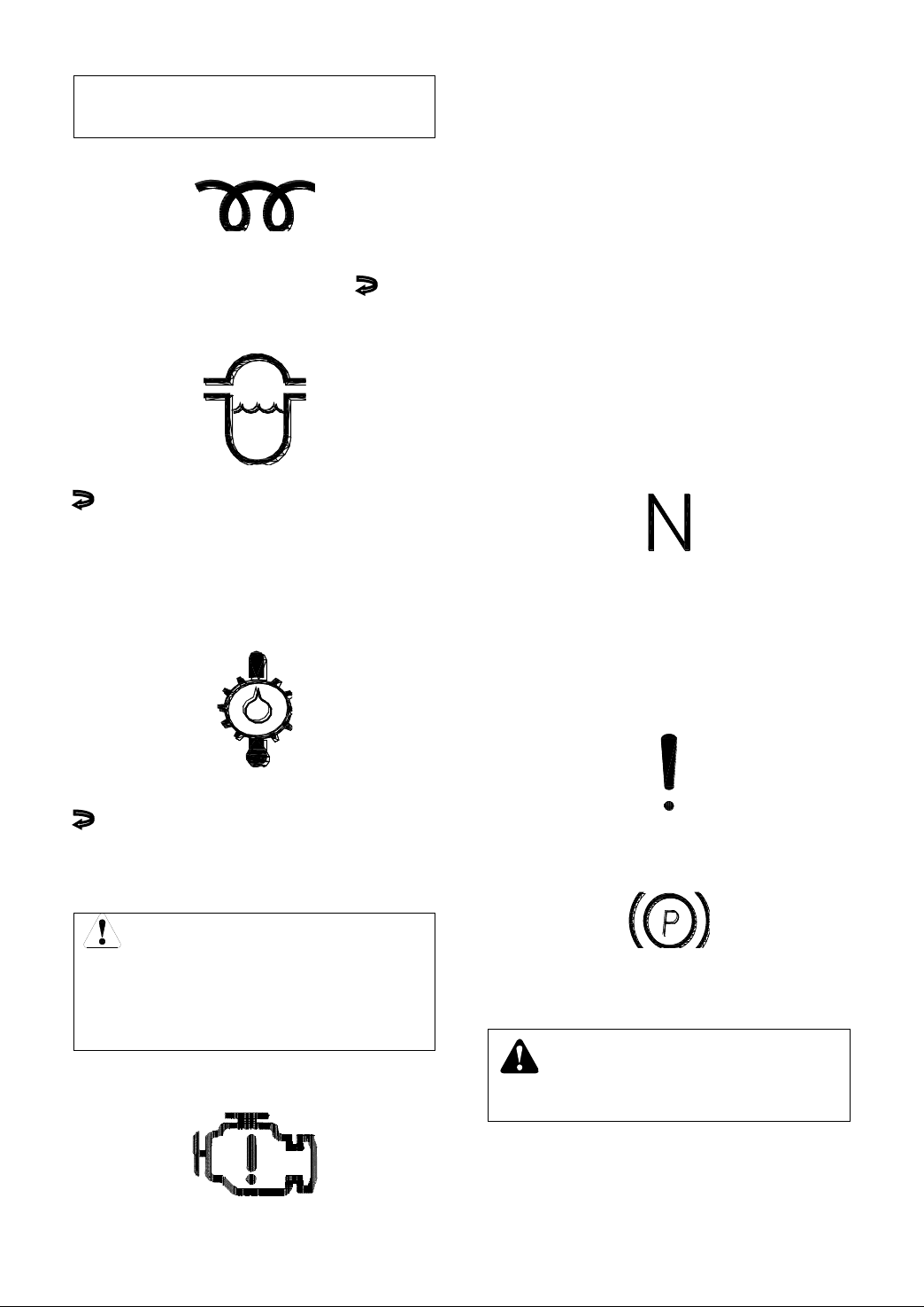
Glow indicator (I) [Diesel truck]
Turn the key to ―ON‖ position and the
indicator lights up for a moment. After the
indicator goes out, turn the key to . ―Start‖
position
Sedimentor indicator (J) [W10,W55,W56
diesel truck]
In normal state, once the starter is set to
―ON‖ position, this lamp lights up. After the
engine is started up, it goes out.
This lamp lights up when water in sedimentor
reaches to a certain level, while the engine is
running.
If this lamp continues to stay lit or lights up
during the engine running, stopping the
engine and discharge water immediately.
Caution
If continue working when the lamp is light.
The fuel injection pump may be damaged.

7
Engine oil pressure alert lamp(K)
This lamp indicates the pressure condition of
engine lube oil. Although it lights up when the
engine switch is set at ―ON‖, once the engine
starts up and the accelerator pedal is pressed,
this lamp goes out.
Caution
If this light continues to stay lit or lights up
during operation, the pressure is lower than
0.05Mpa and should be checked
immediately.
Charging indicator (L)
This lamp indicates the battery condition of
charge. The lamp comes on when the ignition
switch is set at ┃―ON‖, but it goes out as the
engine starts and accelerator pedal is
pressed.
Caution
If the light continues to stay lit or lights up
during operation, the charging rate is low
and should be checked immediately.
Left turning indicator [M]
Right turning indicator [N]
When the truck turns left, the indicator is set
forward, the lamp lights up.
When the truck turns right, the indicator is set
backward, the lamp lights up.
Air filter indicator [O]
When the light is on, it indicates the air inlet
system is blocked, stop the truck and clean
the air filter.

8
(Four-wheel drive rough terrain forklift truck)
Water temperature gauge
This gauge indicates the oil temperature in
the torque converter transmission box when
the key is at ┃(ON) position. In normal status,
LED Displayed in the range of 60 ℃-110 ℃
Caution
If LCD display in the red zone , please stop the
truck at once. Decrease the engine speed to
make the engine cool. Check the cooling fluid if
enough and the fan belt‘s elasticity if fit.
Fuel gauge
The gauge indicates the fuel level in the tank
when the key is at ┃(ON) position.
Suggest filling up the fuel tank after work
every day.
Hour meter
This meter measures working time of engine
when the key is at ┃(ON) position. The meter
increase one number every working hour.
Use meter to schedule lubrication and
maintenance periods.
Caution
When reaching the first 100h, the
spanner logo will flash one hour at
regular intervals to reminder of the
maintenance to the forklift. Refer to
monthly maintenance after first flash.
Refer to periodical maintenance
schedule for per period. Take the actual
flashing time as standard.
Charging indicator
This lamp indicates the battery condition of
charge. The lamp comes on when the ignition
switch is set at ┃―ON‖, but it goes out as the
engine starts and accelerator pedal is
pressed.
Caution
If the light continues to stay lit or lights up
during operation, the charging rate is low
and should be checked immediately.
Engine oil pressure alert lamp
This lamp indicates the pressure condition of
engine lube oil. Although it lights up when the
engine switch is set at ―ON‖, once the engine
starts up and the accelerator pedal is pressed,
this lamp goes out.
Caution
If this light continues to stay lit or lights up
9
during operation, the pressure is lower than
0.05Mpa and should be checked
immediately.
Glow indicator [Diesel truck]
Turn the key to ―ON‖ position and the
indicator lights up for a moment. After the
indicator goes out, turn the key to . ―Start‖
position
Sedimentor indicator [Diesel truck]
In normal state, once the starter is set to
―ON‖ position, this lamp lights up. After the
engine is started up, it goes out.
This lamp lights up when water in sedimentor
reaches to a certain level, while the engine is
running.
Transmission oil temperature warning
light(Hydraulic Forklift)
In normal state, once the starter is set to
―ON‖ position, this lamp lights up. After the
engine is started up, it goes out.
During work time if the oil temperature exceed
the normal rang(60~120。C) the indicator light
on.
Caution
If the pointer enters the red range, stop the
operation instantly and slow down engine
speed to cool the coolant and wait until the
pointer goes into the green range, and have
a check then.
Engine fault indicator
[Electronic-controlled engine]
When the engine gets out of order, this
Indicator will be on. then it must immediately
stop, according to an engine fault table
troubleshooting.
Can be judged according to the fault
indicator lamp (flash code), Can be based on
the fault indicator (flash code) judgment, or
ECU diagnostics port connected to diagnostic
equipment, read the fault code information
stored in the ECU.
For more information, see engine manual.
OnlyCummins engine forklift truck :
When this light is on, it means one important
engine working is beyond the prescribed
limits of engine protection calibration, engine
power can be reduced, you must stop and
check.
Neutral position start-up indicator
[Electric-switch]
Put the steering handle in the neutral position
when truck on the temporarily stop, the light
will indicated on
The truck can be started up only in the neutral
position.
It‘s prohibited for truck in the neutral position
sliping when it‘s on the slope.
OPS indicator [Optional]
When this light is on, it means driver leave the
seats or not sitting on the seat correctly.
Parking indicator
Parking indicator shows on means brake is
affected, Please loosen the parking handle
(hand brake handle), the parking indicator will
shows off.
Warning
It will damage the engine and
transmission, etc. when indicated.
If this lamp continues to stay lit or lights up
during the engine running, stopping the
engine and discharge water immediately.
10
Caution
If continue working when the lamp is light.
The fuel injection pump may be damaged.
Severe warning indicator
[Electronic-controlled engine]
OnlyCummins engine forklift truck:
When this light is on, it indicates the engine is
in severe work condition and the engine
power reduced severely. If condition stays
and starts engine protection shut-down, then
this indicator will flash 30 seconds before
engine shut down to warn the impending
shut-down.
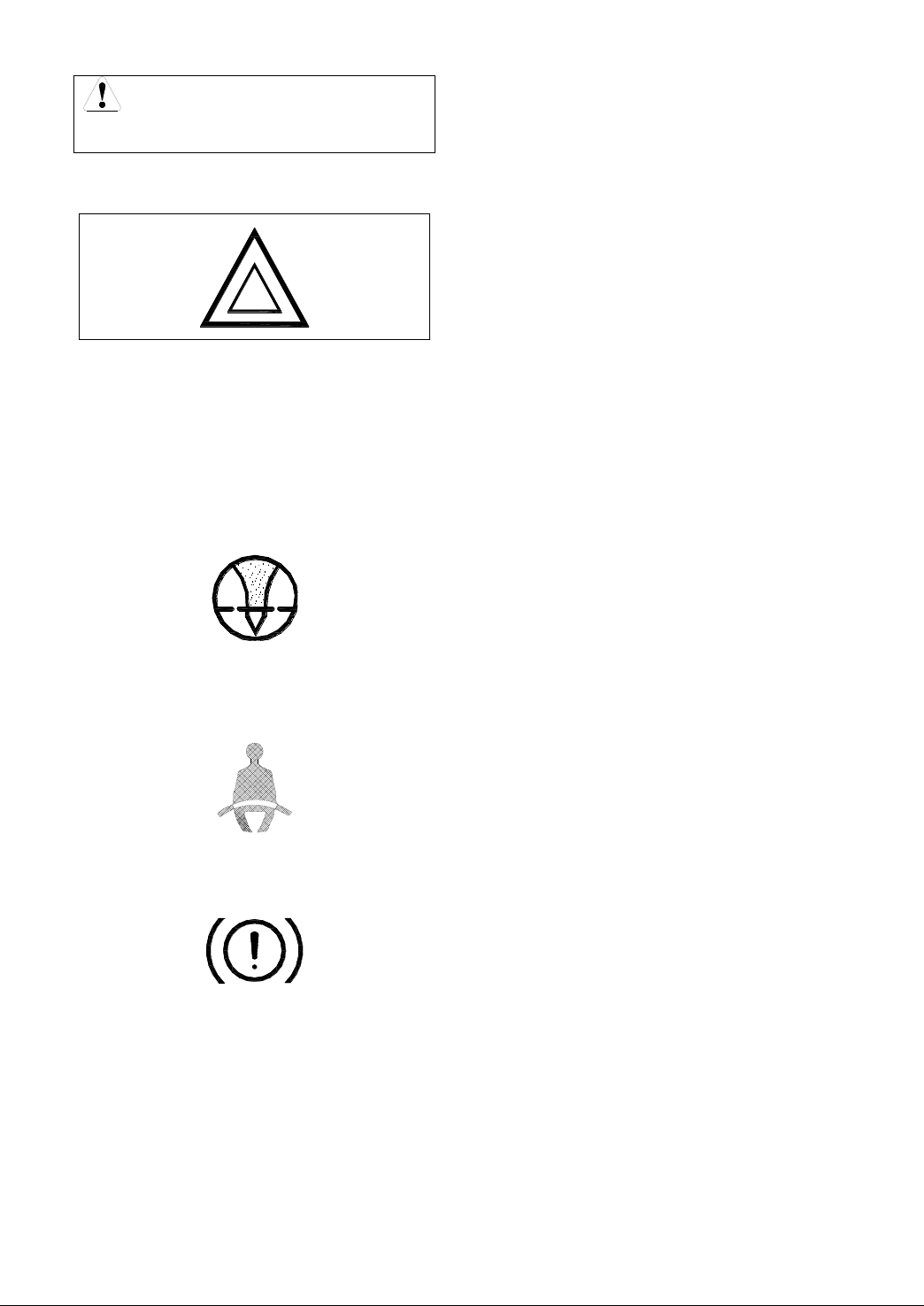
Air filter indicator
When the light is on, it indicates the air inlet
system is blocked, stop the truck and clean
the air filter.
Seat belt warning indicator [Optional]
When thislight is on, it means not wearing a
seatbelt or not locked.
Accumulator warning indicator
This indicator light does not work on the 1-X5
ton forklift.
11
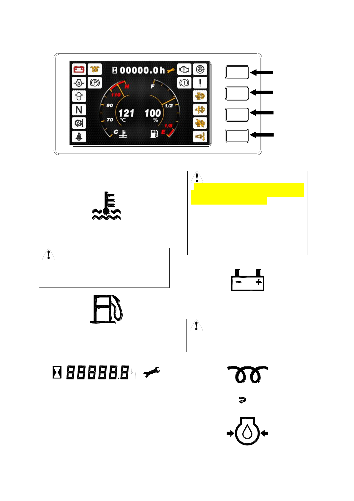
CAN Bus Instrument(W98)
KUBOTA Diesel engine, Main page
A. Instrument indicator lamp
Water temperature gauge
This gauge indicates the oil temperature in the
torque converter transmission box when the key
is at ┃(ON) position. In normal status, LED
Displayed in the range of 40 ℃-110 ℃
Caution
If LCD display in the red zone , please stop the
truck at once. Decrease the engine speed to
make the engine cool. Check the cooling fluid if
enough and the fan belt‘s elasticity if fit.
Fuel gauge
The gauge indicates the fuel level in the tank
when the key is at ┃(ON) position.
Suggest filling up the fuel tank after work every
day.
Hour meter
This meter measures working time of engine
when the key is at ┃(ON) position. The meter
increase one number every working hour.
Use meter to schedule lubrication and
maintenance periods.
Caution
When the time meter increases every
100h (the factory default time interval is
100h, which is adjustable), the spanner
logo will flash one hour at regular
intervals to reminder of the maintenance
to the forklift. Refer to monthly
maintenance after first flash. Refer to
periodical maintenance schedule for per
period. Take the actual flashing time as
standard.
Charging indicator
This lamp indicates the battery condition of
charge. The lamp comes on when the ignition
switch is set at ┃―ON‖, but it goes out as the
engine starts and accelerator pedal is pressed.
Caution
If the light continues to stay lit or lights up
during operation, the charging rate is low
and should be checked immediately.
Glow indicator [Diesel truck]
Turn the key to ―ON‖ position and the indicator
lights up for a moment. After the indicator goes
out, turn the key to . ―Start‖ position
Engine oil pressure alert lamp
This lamp indicates the pressure condition of
KEY4
KEY3
KEY2
KEY1

12
engine lube oil. Although it lights up when the
engine switch is set at ―ON‖, once the engine
starts up and the accelerator pedal is pressed,
this lamp goes out.
Caution
If this light continues to stay lit or lights up
during operation, the pressure is lower than
0.05Mpa and should be checked
immediately.
Parking indicator
Parking indicator shows on means brake is
affected, Please loosen the parking handle (hand
brake handle), the parking indicator will shows
off.
Warning
It will damage the engine and
transmission, etc. when indicated.
Sedimentor indicator [ diesel truck]
In normal state, once the starter is set to
―ON‖ position, this lamp lights up. After the
engine is started up, it goes out.
This lamp lights up when water in sedimentor
reaches to a certain level, while the engine is
running.
If this lamp continues to stay lit or lights up during
the engine running, stopping the engine and
discharge water immediately.
Caution
If continue working when the lamp is light.
The fuel injection pump may be damaged.
Neutral position start-up indicator
Put the steering handle in the neutral position
when truck on the temporarily stop, the light will
indicated on
The truck can be started up only in the neutral
position.
It‘s prohibited for truck in the neutral position
sliping when it‘s on the slope.
Transmission oil temperature warning light
(Hydraulic Forklift)
In normal state, once the starter is set to
―ON‖ position, this lamp lights up. After the
engine is started up, it goes out.
During work time if the oil temperature exceed
the normal rang 60℃~120℃the indicator light
on.
Caution
If the pointer enters the red range, stop the
operation instantly and slow down engine
speed to cool the coolant and wait until the
pointer goes into the green range, and have
a check then.
Seat belt warning indicator [Optional]
When thislight is on, it means not wearing a
seatbelt or not locked.
OPS indicator
When this light is on, it means driver leave the
seats or not sitting on the seat correctly.
Air filter indicator [O]
When the light is on, it indicates the air inlet
system is blocked, stop the truck and clean the
air filter.
Accumulator warning indicator [D]
This indicator light does not work on the forklift.

13
High exhaust temp. lamp
W98Engine:lamp on
Caution
Remind the driver of high exhaust
temperature during regeneration, and pay
attention to safety.
Inhibit Regeneration Lamp
This light indicates that the regeneration state
of the engine is limited and the requested
regeneration cannot be performed at this time.
Caution
Work in an environment that is not suitable
for DPF regeneration. Turn on the
regeneration prohibition. After leaving, the
regeneration prohibition should be lifted in
time to turn off the regeneration prohibition
indicator so that active regeneration can
continue.
Warning
If active regeneration is always prohibited,
the exhaust filter will be blocked, exhaust is
blocked, and the forklift's performance will
deteriorate until the engine fault indicator is
activated .
EATS fault indicator lamp
To indicate that the engine EATS (Exhaust After
Treatment System) has failed or falls outside of
specified operating parameters.
At the same time, the engine fault light is on.
Regeneration Needed/Request Lamp
There are three working states: driving
regeneration, parking regeneration, service
regeneration (after-sale program).
In the first case, the regeneration indicator
lights up permanently and is in the regeneration
working state. No manual intervention is required
at this time, and only the normal working state
needs to be maintained.
The regeneration reminder will automatically
go out, which also means that the particulate
matter processing is completed.
What the driver has to do is to reduce the
light load running time as much as possible in
order to increase the exhaust temperature and
shorten the regeneration time.
In the second case, prompt to stop and start
parking regeneration.
Parking regeneration meets the following
conditions:
①The forklift is parked on a well ventilated flat
road.
②Pull up the handbrake.
③Release the accelerator pedal.
④The reversing operation lever is kept in
neutral (N range).
⑤Preheat the forklift until the water temperature
reaches 70 ℃.
Ahazard warning sign is placed near the exhaust
port.
Turn on parking regeneration (see instrument
key operation instructions).
After the regeneration is complete, the lamp will
turn off automatically, and after 2-3 minutes the
engine returns to normal idle speed, you can
shut down the engine.
Caution
Parking regeneration: parking state, not
conducive to heat dissipation. Keep away
from flammable materials and keep a safe
distance from people.
Drivers should pay attention to protection,
do not leave the scene, and always pay
attention to the engine condition during
regeneration.
It is best not to stop in the middle, otherwise
it is easy to cause DPF failure.
Warning
In case of emergency, parking regeneration
must be prohibited, exit any one of the
parking regeneration conditions ②③④.
W98 Engine
The indicator light flashes during driving. If
the parking regeneration is not performed in time,
it is easy to cause DPF jams and may damage

14
the DPF.
If the regeneration indicator flashes while
driving, and the engine fault indicator also lights
up, stop immediately.
Contact the factory maintenance personnel
or after-sales to check the engine fault code.
After there are no other faults, start parking
regeneration.
Kubota engine
light flashes
Engine fault Code
(SPN: 3701 FMI:15)
The third case is service regeneration.
DPF has been seriously blocked, the engine has
reduced power and torque limit, the forklift
cannot work normally, contact the after-sales
service to complete the service regeneration.
Engine fault indicator [Electronic-controlled
engine]
When the engine gets out of order, this
Indicator will be on. then it must immediately
stop.
Press the key on the right side of the instrument
to view, or ECU diagnostics port connected to
diagnostic equipment, read the fault code
information stored in the ECU.

15
B. Instrument key operation instructions
B.1 Engine fault information display page
(1) KUBOTA diesel engine
No fault
Fault
Back
Next
Prev
Back
①Enter the engine fault information display page: Main page=》Key 4
②Fault query page turning: press key 2 or key 3 to page turning (page turning key is not
displayed when there is no fault at present)
③Return to main page: press key 1 to return to main page
B.2 Forklift operation parameters and interface switching between Chinese and English
①Enter the engine information display page: Main page=》key 2 or key 3
②Language switch: press key 3 to switch language (Chinese / English)
③Return to main page: press key 1 to return to main page
蓄电池电压 发动机转速 机油压力 转速负载
Ash 负载 SOOT 负载 进气温度 行驶速度
%
VDC r/min
℃km/h
%
Bar
%
Battary
Voltage
Ash
Load
Engine
Speed
SOOT
Load
Oil
Pressure
Intake Air
Temperature
Load @
RPM
Vehicle
Speed
%
VDC r/min
℃km/h
%
Bar
%
KUBOTA diesel engine
B.3 Settings page
(1) Set page actions
保养提醒
返回
高级设置
Back
Setting
Enter the setting page: Main page=》Key 1
Enter the maintenance page: Main page=》Key 1=》Key 2, to enter the maintenance
page
Enter the Emissions setting page: Main page=》Key 1=》Key 3, to enter the emissions
setting page
Enter advanced setting page: Main page=》Key 1=》Key 4, Enter the password input
16
page of advanced settings maintenance personnel
Return to main page: press key 1 to return to main page
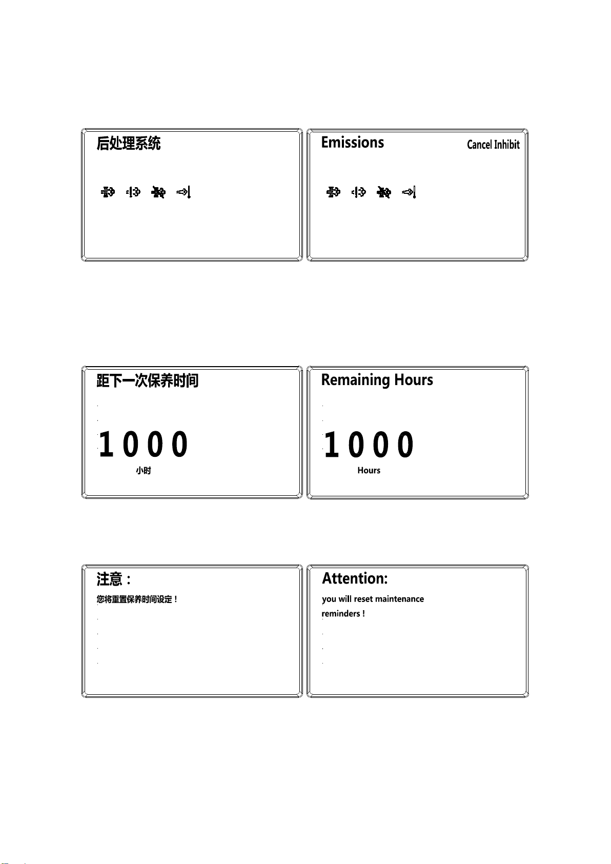
(2) DPF Emissions function setting page (Diesel engine)
请求再生
返回
禁止再生
取消禁止
Regen
Back
Inhibit
Cancel inhibit: press the key 4,The DPF is to burn (DPF-regenerate) trapped particulate
matters in an automatic way.
Inhibit: press key 3,DPF-regenerate function of OFF
Regen: press key 2, Turn on DPF parking regeneration
Return to the setting page: press key 1 to return to the setting page
(3) Maintenance reminder maintenance page
a.Remaining hours query page
重置
返回
Reset
Back
Reset: press the key 2 to jump to the maintenance time reset page to reset the remaining
hours of maintenance to the Set the initial value (maintenance interval).
Back: press key 1 to return to the setting page
b. Maintenance time reset page
确定
返回
Confirm
Back
Confirm:press the key 2 to confirm the reset.After the confirmation, it will automatically return
to the maintenance query page.
Back: press key 1 to return to the setup page.
This manual suits for next models
11
Table of contents
Other HANGCHA Forklift manuals

HANGCHA
HANGCHA R Series User manual

HANGCHA
HANGCHA J Series User manual

HANGCHA
HANGCHA XF Series Quick start guide

HANGCHA
HANGCHA XC Series User manual

HANGCHA
HANGCHA XF Series User manual

HANGCHA
HANGCHA CBD20-AMC1 Installation guide

HANGCHA
HANGCHA CBD15-A2MC1 User manual

HANGCHA
HANGCHA XE Series User manual

HANGCHA
HANGCHA CPD10-A User manual


