HANGCHA XF Series User manual

XF series
Internal Combustion Counterbalanced 1.0t-X5.5t
Forklift Truck
1.5t-X5.5t XF Series Internal Combustion Counterbalanced
Forklift Truck
OPERATION MANUAL
HANGCHA GROUP CO., LTD.

Standard configuration model
Load center distance mm
(in)
500(19.7)
Model
CPD15-
CPD18-
CPD20-
CPD25-
CPD30-
Rated load lifting capacity
kg/ lb.
1500(3300)
1750(3850)
2000(4400)
2500(5500)
3000(6600)
Model
CPD35-
CPD40-
CPD45-
CPD50-
CPD55-
Rated load lifting capacity
kg/ lb.
3500(7700)
4000(8800)
4500(10000)
5000(11000)
5500(12000)
Load center distance mm
(in)
600(23.6)
Model
CPD15-
CPD18-
CPD20-
CPD25-
CPD30-
Rated load lifting capacity
kg/ lb.
1350(3000)
1600(3500)
1800(4000)
2250(5000)
2700(6000)
Model
CPD35-
CPD40-
CPD45-
CPD50-
CPD55-
Rated load lifting capacity
kg/ lb.
3200(7000)
3650(8000)
4000(9000)
4500(10000)
5000(11000)
CE model: Optional maximum lift height: 6000 mm
Caution
Bearing Capacity Chart
The chart shows the relationship
between the location of the load center
distance and the maximum load. Check
whether the load and the load center
distance are within the allowable range
of the Bearing Capacity Chart before
loading. If the load shape is irregular,
the heaviest part should be placed in
the center of the fork and close to the
backrest.
Load center
distance
Note: The model tonnage number displayed below is calculated at a load center distance
of 500mm.
©September 2022, HANGCHA GROUP CO., LTD.

Contents
I. Instructions for use........................................................................................................1
II. Forklift truck component names...................................................................................3
1. Instrumentation .............................................................................................................................3
2. Controls and switches .................................................................................................................12
3. Body and other parts ...................................................................................................................17
III. Safety regulations .....................................................................................................22
IV. Daily safety checks...................................................................................................28
V. Forklift truck structure and stability ...........................................................................32
VI. Operation..................................................................................................................35
1. Start.............................................................................................................................................35
2. Operation.....................................................................................................................................35
3. Loading .......................................................................................................................................36
4. Stacking.......................................................................................................................................37
5. Unstacking ..................................................................................................................................37
IX. Various signs and labels ...........................................................................................38
X. Lifting, handling and towing of the forklift truck .......................................................44
XI. OPS system description............................................................................................45
XII. Cab and overhead guard..........................................................................................47
XIII. Precautions for use of the LPG forklift truck..........................................................48
XIV. How to use and maintain the lead-acid battery .......................................................60
XV. Use, installation and safety rules for accessories......................................................64
XVI. Optional configuration of driver's seat handrail for fingertip control.......................67

1
I. Instructions for use
In order to ensure personal and equipment safety, the driver should obey the following Precautions:
1. Only drivers with proper training and a valid license should operate the vehicle.
2. Check each control and alarm device before driving, if any damage or defects are found they should
be repaired before operation.
3. The load should not exceed the specified value when handling; the forks should be fully inserted
into the load so that it is uniformly positioned on the fork; do not use a single fork to lift cargo.
4. Start, turn, drive, brake and stop smoothly; slow down on wet or slippery roads when steering.
5. Loads should be placed as low as possible, and the mast should tilt backward when driving.
6. Be careful when driving on ramps; move forward when driving up gradients greater than one in ten
and move back when driving down ramps; do not turn when driving up or down ramps; do not carry
out loading and unloading operations when the forklift is in motion.
7. Pay attention to pedestrians, barriers, and bumpy surfaces when driving and be aware of the upper
clearance of the forklift truck.
8. Do not stand on the forks and do not carry passengers.
9. Do not stand under the forks or walk under the forks.
10. Do not operate the truck and its accessories from anywhere except the driver’s seat.
11. Do not handle unsecured or loosely stacked cargo and be careful when handling large cargos.
12. Protect cargo on high lifting forklift trucks with a lift height of more than 3m from falling down and
take preventive measures if necessary.
13. Try to tilt the mast backward when the high lifting forklift truck is in operation and tilt forward
within the minimum range during loading and unloading operations.
14. When driving on wharfs or temporary decking, you should be extra careful and drive slowly.
15. The driver should not stay in the truck and should shut down the engine when refuelling; keep
sources of ignition away when checking the battery or fuel tank level.
16. When a forklift truck with accessories is idling, it should be operated in the same manner as a
loaded forklift truck.
17. Drop the forks to the ground, switch the gear lever to the neutral position, pull the parking brake
device properly, shut down the engine, and disconnect the power when leaving the truck. Engage the
parking brake device properly when parking on ramps, place cushion blocks under the wheels when
parking for a long time.
18. In case of a sudden fault when lifting cargo or driving on gradients, causing leakage of storage
battery electrolyte, hydraulic oil and brake fluid, or a flat tire etc., personnel should be organized for
repair immediately, the truck should be kept in a safe condition, and professional maintenance
personnel or the seller should be contacted.
19. Noise and vibration will be generated during installation and assembly processes; please choose
proper tools and assembly methods to reduce the impact of noise pollution on the environment.
20. The forklift truck must not be used in plant areas; the working surface should be solid and flat
cement pavement, asphalt pavement or concrete pavement. When there is snow, ice, water or other
foreign matter on the road, the truck can only be used after it has been fully cleared away; otherwise,
the truck is likely to lose control, resulting in an accident.
21. In the event of a breakdown, the truck should be first moved to a place where it does not obstruct
traffic. If the breakdown is caused by the brake system or steering system, the truck should be carried

2
away with a proper carrier loader (see the vehicle handling content); if it is caused by other reasons,
the truck should be towed with an appropriate vehicle; tow rope should be fixed outside the truck
body when towing. Obey traffic rules when towing a truck on the highway.
22. Do not operate the forklift truck or carry cargo after disassembling the internal combustion engine
hood, water tank cover plate, overhead guard, mast backrest or other protective devices.
23. There should be sufficient lighting in the truck working area. Turn on the head lights when working
at night and there should be sufficient lighting in the work area.
24.Do not conduct side shift operations when a forklift truck with automatic adjustable distance forks
is loaded to protect the forklift truck from losing balance and damaging components.
25. The 5T-10t forklift truck is provided with an energy accumulator, which can provide at least one
emergency braking operation after the forklift truck has been shut down; in order to ensure your
safety, please carefully read and strictly implement operations related to the energy accumulator in
the manual.
26. Please do not tilt the mast forward or backward or lift the mast to the extreme position during
idling where possible before the temperature of the hydraulic oil rises.
27. Do not revise or modify the forklift truck without the written approval of the forklift truck
manufacturer in advance; otherwise, it may affect the rated load and stability or safe operations. This
includes: Assembly and disassembly of brake, steering, visibility devices and accessories. When the
forklift truck manufacturer agrees to revise or modify the truck, he/she should also agree to update
and properly revise the bearing nameplate, label, and operation and maintenance manual.
28. If the user refits the forklift truck, it may introduce hazards or risks that the manufacturer did not
consider, thus the existing forklift truck risk assessment will become invalid.
Forklift truck refitting outside Europe should conform to regional requirements (see ISO/TS 3691-8).

3
II. Forklift truck component names
1. Fork
2. Backrest
3. Lifting hydraulic
cylinder
4. Mast
5. Steering wheel
6. Overhead guard
7. Counterweight
8. Driver’s seat
9. Rear wheel
10. Frame
11. Hood
12. Tilt cylinder
13. Front wheel
1. Instrumentation
Diesel Engine Homepage (Xinchai / Kubota)
Key 4
Key 3
Key 2
Key 1
1
2
3
4
6
57
8
9
10
11
12
13

4
GCT Engine Homepage
Key 4
Key 3
Key 2
Key 1
H11/ H12 Engine Homepage
Key 4
Key 3
Key 2
Key 1
A. Instrument indicator lights
Water temperature gauge
When the ignition key switch is in the ┃ (open)
position, the water temperature gauge is active,
displaying the engine coolant temperature; in
normal operation the LCD will show that it is
within the range 40℃-110℃.
Caution
Stop operation immediately and reduce
engine speed to cool down the engine and
then stop the engine when the gauge is in the
red area. Check the coolant level is sufficient
and whether the fan belt is tight.
Fuel gauge
When the ignition key switch is in the ┃ (open)
position, the fuel gauge will display the
approximate fuel quantity of the fuel tank.
It is recommended to fill up the fuel tank every
day after work.
Stopwatch
When the ignition key switch is in the ┃ (open)

5
position, the stopwatch will start running. The
stopwatch reading will increase by one digit for
every hour of operation.
The stopwatch displays the cumulative working
hours of the forklift truck.
Caution
After the cumulative hours reaches 100h
(the factory default interval is 100h, and it
can be adjusted) displayed on the
stopwatch, the “wrench” icon will flash for 1
hour and prompt that the forklift truck
needs to be serviced. See monthly
maintenance after the first flash. See the
information about maintenance cycle
schedule in detail for each cycle. The specific
flash time depends on the actual situation.
Charging indicator light
The light displays the battery charge status,
turns on when the starting switch is in the ┃
(open) position, and turns off when the engine
is started.
Caution
If the light continues to turn on or flash
during operation, it indicates that the
charging is abnormal and immediate
inspection is required.
Preheat indicator light [diesel forklift truck]
The light turns on for a short period after the
switch is moved to the ┃ (open) position, and
the switch can be moved to the (start)
position for starting after the light turns off.
Engine oil pressure alarm indicator light
The light indicates the pressure of engine
lubricating oil.
Caution
If the light continues to turn on or flash
during operation, it indicates that the oil
pressure is less than 0.05MPa and immediate
inspection is required.
Parking indicator light
When the light turns on, it indicates that the
parking brake is applied. In order to drive the
truck, the parking brake lever (e.g., hand brake
lever) should be released; at that time, the
light turns off.
Warning
Driving the truck when the light is on may
cause damage to the engine, drive system
and other parts.
Oil-water separator indicator light [diesel
forklift truck]
The light turns on when the water level reaches
a certain level when the engine is running.
If the light continues to turn on or flash when
the engine runs, the engine should be shut
down immediately to discharge water.
Caution
If operation is continued after the light turns on, the
fuel oil injection pump may be damaged.

6
Neutral start indicator light
When the truck is temporarily stopped, the
direction lever should be in the neutral
position; at that time, the light turns on.
The truck can only be started when it is in
neutral.
The truck must not be in the neutral position
when driving downhill.
Gearbox oil temperature alarm light [hydraulic
forklift]
When the engine is running and the gearbox
oil temperature exceeds the normal range
(60℃-120℃), the alarm light will turn on.
Caution
If the alarm light turns on, please stop
operation immediately and reduce engine
speed to cool down until the light turns off.
Otherwise, the oil quantity should be checked
or other inspections should be conducted.
Safety belt alarm indicator light (optional)
When the start key is in the “┃”, position, the
engine is not started and the driver is not on
the driver's seat. If the safety belt is not
fastened properly, the safety belt alarm
indicator light will turn on.
If the safety belt is not fastened or loose when
the driver is operating the vehicle, the buzzer
alarm will sound and the safety belt alarm
indicator light will turn on at the same time.
This is to remind the driver to safely park and
refasten the safety belt; then, the buzzer alarm
will stop and the safety belt alarm indicator
light will turn off.
Air cleaner alarm indicator light
When the light turns on, it indicates that the
air cleaner of the air intake system is blocked
and the truck has to be stopped to clean the air
cleaner.
Engine fault indicator light [for forklift trucks
with an electronically controlled engine]
When the light turns on, it indicates that there
is a fault and the truck has to be stopped
immediately.
Maintenance personnel can press the right key
of the instrument to check or connect the ECU
diagnosis interface with the diagnostic
equipment to read the fault code information
stored in the ECU.
Low brake pressure alarm indicator light
The indicator light in the 1.0t-X5.0t forklift
truck is not operative.
OPS indicator light
When the light turns on, it indicates that the
driver is not on the driver's seat or is not sitting
properly.

7
Gasoline engine / LPG engine: H1, H3
Engine fuel: Gasoline
Engine fuel: LPG
ECO: Low LPG capacity prompts
that it should be supplemented
soon.
The fault diagnosis tester is
connected with the indicator
light
Regen indicator light
There are three kinds of working mode: Driving
regen, parking regen, and service regen
(aftersales solution).
In the first case, the regen indicator light turns
on normally and is in the regen working status.
At that time, manual intervention is not
required and normal operation can be
maintained. The light will automatically turn off
after the regen prompt, which also indicates
that the treatment of particulate matters is
completed.
The driver should reduce light running time as
much as possible to increase the exhaust
temperature and shorten the regen time.
In the second case, it prompts that the parking
regen should be started.
Start parking regen (see operating instructions
for instrument keys) after meeting parking
regen conditions.
Parking regen conditions:
①The forklift truck is parked on a
well-ventilated flat road.
②Pull the hand brake.
③Release the accelerator pedal.
④Keep the direction lever in the
neutral position (gear N).
⑤Warm up the forklift truck until
the water temperature reaches 70℃.
⑥Install the hazard Warning sign
near the exhaust port.
Caution
Parking regen: The parking status is not
suitable for heat dissipation. Stay away from
inflammables and keep a safe distance from
people.
The driver should pay attention to safety,
should not leave the site, and should monitor
the engine conditions during regen.
The driver should not stop the engine during
regen as this is likely to cause a DPF fault.
Warning
In case of emergency, parking regen is
inhibited, and only one of conditions
②③④ to exit parking regen needs to be
met.
The regen indicator light turns on when driving
and the forklift truck can continue to be used
normally or can be driven to a safe position for
parking regen.
If the regen indicator light turns on when
driving and the engine fault indicator light
turns on as well, maintenance personnel or
aftersales staff for the plant area should be
contacted to check the engine fault code. Start
the parking regen after confirming that there is
no other fault.
Caution
If the two indicator lights turn on and there is
no parking regen within 2h, the DPF is likely to
be blocked, the parking regen will fail to start,
and DPF may be damaged, causing
maintenance expenses.
H7/ H8
diesel
engine
Flash
Fault code
SPN:5270 FMI:15
W97,
W98,
W99
Diesel
engine
Flash
Fault code
GASO
LINE
LPG
HDM
3000

8
SPN:3701 FMI:15
At the end of parking regen, the light will
automatically turn off; the engine can be shut
down after waiting for 2-3min until the engine
restores to normal idling.
In the third case, service regen.
H7/ H8
diesel
engine
Flash
Fault code
SPN:50261 FMI:15
W97,
W98,
W99
Diesel
engine
Flash
Fault code
SPN:3701 FMI:16
When the DPF has been severely blocked, the
engine has reduced power and torque, and the
forklift truck does not work normally, aftersales
staff should be contacted for service regen.
Exhaust system fault indicator light
If the EATS has a fault or exceeds the
designated operating parameters, the engine
fault light should turn on at the same time.
Inhibit indicator light
When the light turns on, it indicates that the
regen status of the engine is restricted and
driving regen or parking regen is inhibited.
Caution
When working in an environment that is not
suitable for DPF regeneration, turn on the
inhibit mode. After leaving, release the inhibit
mode promptly so that active regeneration
can continue.
Warning
If the active regen has been inhibited, the
exhaust filter and exhaust will become
blocked and the working performance of the
forklift truck will be degraded until the engine
fault indicator light is activated.
High exhaust temperature indicator light
Caution
Light on: Reminds the driver that the regen
process causes high exhaust temperature and
to pay attention to safety.
9
B. Operating instructions for instrument keys
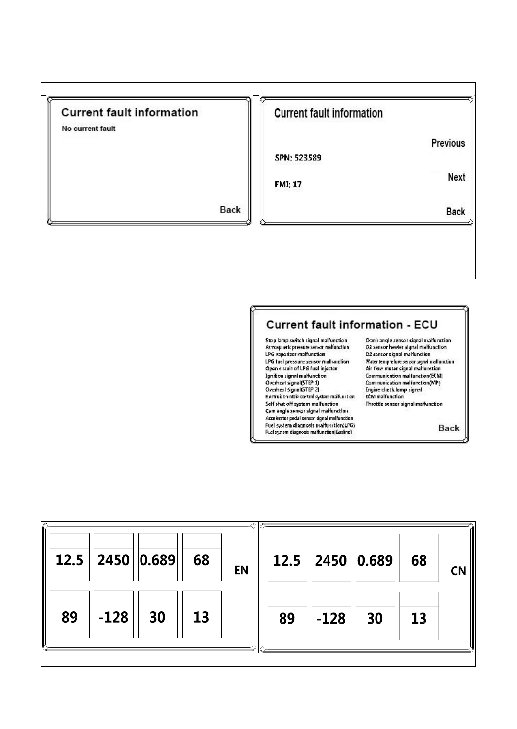
B.1 Engine fault information display page
(1) Diesel engine (Kubota/Xinchai) and H11/H12 engine
No faults
Fault present
① Enter the engine fault information display page: Homepage=》Key 4
② Fault query page selection: Press key 2 or key 3 again for page selection (the page selection key is
not displayed when there is no fault)
③ Back to the homepage: Press Key 1 to return to the homepage
(2) GCT engine
① Enter the engine fault information
display page:
Homepage=》Key 4
② Back to the homepage:
Press Key 1 to return to the homepage
Note: GCT engine fault information
(English) will be directly displayed
according to fault content.
B.2 Forklift truck operating parameters and Chinese and English interface switch
① Enter the forklift truck operating parameter display page: Homepage=》Key 2 or Key 3
② Language switch: Press Key 3 again to switch language (CN/EN)
③ Back to the homepage: Press Key 1 to return to the homepage
Diesel engine (Kubota/Xinchai)
蓄电池电压 发动机转速 机油压力 转速负载
Ash 负载 SOOT 负载 进气温度 行驶速度
%
VDC r/min
℃km/h
%
Bar
%
Battary
Voltage
Ash
Load
Engine
Speed
SOOT
Load
Oil
Pressure
Intake Air
Temperature
Load @
RPM
Vehicle
Speed
%
VDC r/min
℃km/h
%
Bar
%
10
GCT engine
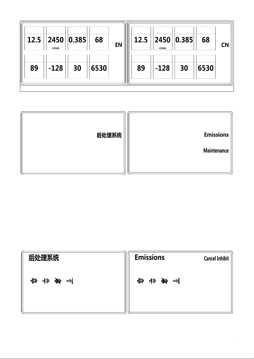
B.3 Setting page
(1) Operations on the setting page
⚫Enter the setting page: Homepage=》Key 1
⚫Enter the maintenance page: Homepage=》 Key 1=》 Key 2, enter the maintenance repair
page
⚫Enter the emissions system setting page: Homepage=》 Key 1=》 Key 3, enter the emissions
system setting page
⚫Enter the advanced setting page: Homepage=》 Key 1=》 Key 4, enter the advanced setting
maintenance personnel password input page
⚫Back to the homepage: Press Key 1 to return to the homepage
(2) DPF emissions function setting page (diesel engine)
Cancel inhibit: Press Key 4 and enable the DPF automatic regen function
Inhibit: Press Key 3 and disable the DPF automatic regen function
%
VDC
?℃us
%
kg/cm2
蓄电池电压
A / F
Alpha
发动机转速
点火正时
LPG 压力
进气温度
充电效率
喷射脉宽
Battary
Voltage
A / F
Alpha
Engine
Speed
Ignition
Timing
LPG Fuel
Pressure
Intake Air
Temperature
Charging
Efficiency
Injection
Pluse Width
%
VDC
?℃us
%
kg/cm2
保养提醒
返回
高级设置
Back
Setting
请求再生
返回
禁止再生
取消禁止
Regen
Back
Inhibit

11
Regen: Press Key 2 and enable the DPF parking regen.
Back: Press Key 1 to return to the setting page
(3) Maintenance repair page
a. Remaining hours query page
The remaining hours can be observed on the page
Reset: Press Key 2 to be redirected to the maintenance hour reset page and reset the remaining
hours to the set initial value (maintenance cycle interval).
Back to the setting page: Press Key 1
b. Maintenance hour reset page
Reset: Press Key 2 to confirm reset and automatically return to the maintenance query page if the reset
confirmation is successful.
Back to the setting page: Press Key 1 to return to the setting page
重置
返回
Reset
Back
确定
返回
Confirm
Back

12
2. Controls and switches
Control and Switch Diagram of the 1.0T~x5.5t Forklift Truck
1. Steering wheel
2. Horn
3. Combination light switch
4. Ignition key switch
5. Lifting lever
6. Tilt lever
7. Cup holder
8. Instrument
9. Rocker switch
10. Accelerator pedal
11. Brake pedal
12. Inching pedal
13. Hand brake lever
14. Steering wheel adjustment switch
15. Direction lever
16. Brake fluid flap
17.Emergency power-off switch
(optional)
12365
47
8
9
12 11
10
14
16
15
13

13
Steering wheel [1]
Controls the driving direction of the truck
Anticlockwise rotation
turns the truck to the left; clockwise rotation
turns the truck to the right.
Warning
The forklift is equipped with a fully hydraulic
steering mechanism. When the engine shuts
down, it will be very difficult to steer the
forklift. Before turning again, the engine must
be restarted immediately.
Horn button [2]
The horn will sound by pressing the horn
button in the center of the steering wheel.
Combination light switch [3] (Indicator light
and light combination light switch)
The indicator light switch is on the right side of
the steering column and the switch is toggled
when turning.
Push forward-left turn indicator light;
N-neutral; Pull back-right turn indicator light.
The indicator light switch does not return to
the neutral position automatically and must be
reset manually.
To turn on the headlights and the front signal
light, turn this switch to align the position
marker on the switch handle with the
corresponding symbol on the switch body.
Ignition key switch [4]
O (off): The position to insert and pull out the
key; when the key is in this position, the engine
shuts down.
┃(On): When the start key is in “┃”, the circuit
is connected; after the engine is started, the
key remains in this position.
(Start): When the key is in the “ ”
position, the engine is started; after the engine
is started, the key automatically returns to the
“┃” position after release.
Diesel engine
When starting, the key is turned to the “┃”
position and the preheat indicator light [I]
turns on for a while; after the light turns off,
the key can be rotated to the “ ” position to
start the engine.
Caution
1. When the engine stops, do not leave the
key in the “┃” position to avoid battery
discharge.
2. When the engine is running, do not put the
key in the “ ” position to avoid motor
damage.
3. When starting, the starter motor cannot
continuously rotate for more than 10s and the
Turn left Turn right

14
interval between consecutive starts should be
120s.
Lifting lever [5]
This lever is used to lift or lower the forks.
Push forward - Down; Pull back - Up
The lifting speed is controlled by the backward
tilt angle of the lever and the accelerator pedal.
The lowering speed is only controlled by the
forward tilt angle of the lever.
Tilt lever [6]
This lever is used to tilt the mast forward and
backward.
Push forward - Forward tilt; Pull back -
Backward tilt
The tilt speed is determined by the tilt angle of
the lever and the throttle control.
Caution
The multiway valve is equipped with a
forward tilt self-locking valve. Therefore,
when the engine shuts down, the mast
cannot tilt forward even if the tilt lever is
pushed forward.
Side shift control lever (optional)
Accessory control lever (optional)
This lever is used to move the side shift frame
to the left or right.
Push forward – Move left; Pull back – Move
right
The side shift speed is determined by the tilt
angle of the lever and the throttle control.
Different types of accessories with different
functions are optional, thus the driver has to
be familiar with the operating method for each
accessory.
Cup holder [7]
A cup holder is set on the right side of the
instrument stand for the driver to place a cup.
Rocker switch [9] [optional configuration]
1. Alarm light switch: When pressing down, the
alarm light will flash; when pressing up, the
alarm light will turn off.
2. Rear headlight switch: When pressing down,
the rear headlight will turn on; when pressing
up, the rear headlight will turn off.
Rocker switch in a truck with a cab may be
different. Ventilation, demisting or other
Lift
Lower
Tilt forward
Tilt backward
Move to the left
Move to the right

15
functions are added.
Accelerator pedal [10]
When the accelerator pedal is pressed, the
engine speed and the truck speed will increase;
when the accelerator pedal is released the
engine speed and the truck speed will
decrease.
Brake pedal [11]
When the brake pedal is pressed the truck
slows down; when the brake pedal is pressed
to the bottom, the truck stops. When the pedal
is released the truck runs freely.
Caution
Avoid emergency braking. Emergency braking
can easily cause the truck to tilt or cargo to fall,
resulting in accidents.
Inching pedal [12]
When the pedal is pressed, the oil pressure of
the hydraulic clutch will drop. When the pedal
is pressed harder, the forklift truck will be
braked. The pedal can be used when the
forklift truck slows down to approach cargo or
conducts loading and unloading operations.
Caution
Do not use the inching pedal excessively. If the
pedal is used as a footrest or used for a long
time, it may cause overheating of the
automatic transmission oil or clutch slip.
Hand brake lever [13]
Pull the lever back to engage and push the
lever forward to release. Engage the lever
before the leaving the forklift truck.
Caution
In case of brake system failure or emergency,
the lever can be engaged for emergency
braking. Do not use the hand brake to slow
down during normal use.
Adjusting lever for steering wheel tilt angle [14]
The position of the steering wheel can be
adjusted. To perform adjustment, pull the
adjusting lever installed on the left side of the
steering hub column, move the steering wheel
to the desired position, and push down the
11
12
14

16
adjusting lever for locking.
Caution
a. Adjust the steering wheel tilt angle after
the forklift truck has stopped and the hand
brake is engaged.
b. Forcibly move the steering wheel up and
down to ensure that it has been locked after
adjusting.
Direction lever [15]
The direction lever is installed on the left side
of the steering hub column. This series of
forklift trucks adopt electrical steering and the
functions realized by moving the lever forward
and backward are as follows:
1.5~X5.5t
F
Forward
N
Neutral
R
Reverse
4.0~x5.5t
F
Forward
N
Neutral
R
Reverse
Press the brake pedal to the bottom to fully
stop the truck before changing the driving
direction; push the lever forward to engage
forward gear I; pull up and push the lever
forward to engage forward gear II from gear I.
Press the brake pedal to slow down if it is
required to reverse; pull back the lever to
engage reverse gear I; pull up and push the
lever back to engage reverse gear II from
reverse gear I.
Caution
The engine can only be started when the
lever is in the neutral position.
Emergency power-off switch [17]
Press down the emergency power-off switch to
disconnect the electric appliances from the
battery.
If the forklift truck needs to be restarted, the
emergency power-off switch should be
toggled.
Close the emergency power-off switch 30s
after shutdown.

17
3. Body and other parts
Load-backrest
The load-backrest ensures the stable loading of
cargos. The forklift truck must not be operated
without a load-backrest.
Driver's seat
1. Driver's seat weight adjusting handle
2. Forward and backward adjusting handle for
the driver's seat
3. Backrest angle adjusting handle
4. Handrail adjusting knob
· Driver's seat weight adjustment
According to the user’s weight, the weight
adjusting lever can be lifted up and moved
horizontally until the user gets comfortable.
· Forward and backward adjustment of the
driver's seat
Pull the adjustment handle inward by hand,
then push the whole seat forward and
backward to reach the desired position, the
handle is automatically locked when lowered
· Backrest angle adjusting
While sitting on the driver's seat, lean back on
the backrest, pull the backrest angle adjusting
lever upward with your left hand, lean forward
or backward, and release the lever until the
backrest angle reaches the desired position.
·Handrail adjusting
The handrail tilt angle can be adjusted by
rotating the adjusting knob. When rotating the
knob outward, the front end of the handrail
will lift. When rotating the knob inward, the
front end of the handrail will lower.
Warning
⚫The ignition key switch must be
turned off before adjusting the driver's
seat.
⚫The seat position can be adjusted
when the forklift truck has stopped.
⚫Do not adjust the driver's seat
when driving to avoid an accident.
⚫For front and rear adjustment and
backrest angle adjustment, the handle
should be pulled in place to ensure that
the structure is completely disengaged
before adjustment.
⚫After adjustment, the levers should
return to the locked position. Ensure that
all the components are locked securely
before using the forklift truck.
Safety belt
·Fasten the safety belt
An auxiliary action is required before pulling
out the safety belt which may require some
familiarization.
One type of seat: You need to press the white
round button (with the text "press to release")
with one hand, and then the seat belt can be
pulled out with the other hand. Then, the belt
can be inserted into the socket on the other
side of the driver's seat.
You may also encounter another kind of
driver's seat: The driver's seat with a rotating
safety belt box. When the safety belt box is
rotated forward, the safety belt cannot be
pulled out; when the box is rotated backward,
the safety belt can be pulled out and inserted
into the socket on the other side of the driver's
seat; the safety belt box must be rotated
forward again to return to the normal working
position.
Your back and waist should be as close to the
driver's seat as possible when fastening the
safety belt. Do not fasten the safety belt at the
abdomen.
Do not tilt the backrest too much; otherwise,
the safety belt will not be extended correctly.
Do not knot or twist the belt.
1
2
3
4
Other manuals for XF Series
1
This manual suits for next models
10
Table of contents
Other HANGCHA Forklift manuals

HANGCHA
HANGCHA J Series User manual

HANGCHA
HANGCHA R Series User manual

HANGCHA
HANGCHA CPCD30/35-XW43E-RT Quick start guide

HANGCHA
HANGCHA XC Series User manual

HANGCHA
HANGCHA XE Series User manual

HANGCHA
HANGCHA CPD10-A User manual

HANGCHA
HANGCHA CBD20-AMC1 Installation guide

HANGCHA
HANGCHA XF Series Quick start guide

HANGCHA
HANGCHA CBD15-A2MC1 User manual


