HanleyLED PHOENIX NRG BAR User manual

1.30.18
• Game Saving Solution, made with High Eciency Everything!
• Exceptionally Bright: 69% Brighter Output
• Most Versatile & Cost Eective Cabinet LED Bar!
• Phoenix Lens for more space between bars
• Can be cut to size
• Ideal for New Construction or HO Lamp Replacement
• 24volt system
• Ships in compact boxes for easy drop-shipping anywhere!
• Guaranteed Life over 50,000 hours
• DIY Layout Tool at hanleyledsolutions.com
(Available in English, Spanish and French)
Want to make your shop Highly Ecient, too?
Reduce install mistakes and improve eciency by transforming your shop with our 24volt System. With our 24volt PhxNRG MODULES,
our 24volt PhxNRG BARS & 24volt Wing Span products, you only need 24volt Hanley Premium Power Supplies stocked in your shop.
LM79
LM80
L70:5+ YEARS
7 5
GENERAL PURPOSE
RETROFIT SIGN
CONVERSION
FOR USE ONLY IN
ACCORDANCE WITH KIT
INSTRUCTIONS
KIT IS COMPLETE ONLY WHEN ALL PARTS
REQUIRED BY THE INSTRUCTIONS ARE PRESENT
2
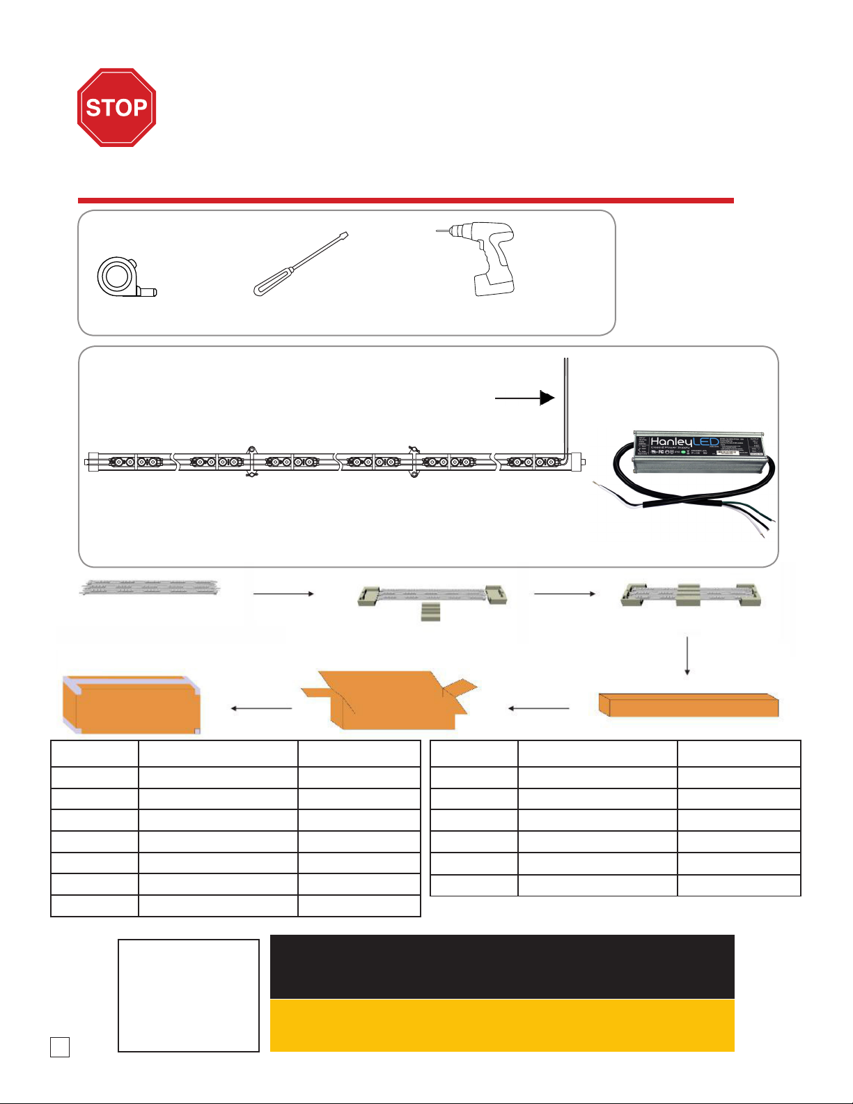
READ THESE INSTRUCTIONS COMPLETELY AND CAREFULLY
24v Power Supply
Tools required:
Components:
• Retrot (RF) Connector is already screwed onto ends
• Simply remove screw & cap for new construction signs
• PhoenixNRG Bars come with a 1 ft whip
NOTE:
All materials removed
must be disposed of
in accordance with
applicable local, state,
and federal laws.
WARNING check polarity: All connections must be WHITE-TO-RED (+) and BLACK-TO-BLACK (-).
Reverse polarity connections may damage the LEDs and will void product warranty.
Caution: Turn o power to sign before inspecting or removing existing light source.
Power must remain o while installing the Concorde Cabinet System.
Screwdriver Electric Drill
Tape Measure
BEFORE YOU BEGIN
Determine your light bar mounting method. Are you using pre-existing sockets to mount?
If so, Retrot Connectors are already attached to the PhoenixNRG Bars. For a new
construction simply remove screw & cap.
Phoenix NRG Bar
1 ft whip
Item Bars Per Box Bars Per Case
HPEB-2S24 3 12
HPEB-2S30 3 12
HPEB-2S36 3 12
HPEB-2S42 3 12
HPEB-2S48 3 12
HPEB-2S60 2 8
HPEB-2S64 2 8
Item Bars Per Box Bars Per Case
HPEB-2S72 2 8
HPEB-2S84 2 8
HPEB-2S96 2 8
HPEB-2S108 2 8
HPEB-2S117 28
HPEB-2S120 2 8

RETROFIT INSTALLATION GUIDE
This guide is designed to aid in the installation of HanleyLED’s Phoenix NRG Bar. Skilled trades people that are familiar with general
construction, electrical, and sign installation techniques should do the installation. Licensed electricians should provide all installation
and hook-up of both the primary and secondary input/outputs of the HanleyLED power supply. All installation and hook-up should
be done in accordance with all National and Local codes and permits. In no way is this document intended to construe warranty or
tness of use of the products described, nor is it intended to provide safety instruction for those installing the product.
Step 1
Remove existing neon or uorescent bulbs by having a licensed electrician disconnect and remove the neon transformers or
uorescent ballasts. Remove existing neon and standos or uorescent lamps. Leave uorescent sockets in cabinets with leads
disconnected. This should leave an empty channel letter or cabinet.
Step 2
Using a non- oil based cleaner, clean the back surfaces of the channel letter or cabinet where the LED modules will be mounted.
This is an important step for good adhesion of HanleyLED modules mounting tape.
Step 3
Installer should examine all parts that are not intended to be replaced by the retrot kit for damage and replace any damaged
parts prior to installation of the retrot kit. Do not make or alter any open holes in an enclosure of wiring or electrical
components during kit installation. Any existing holes in the letters or cabinet that will not be used in the installation of HanleyLED
modules should be patched to avoid water damage. Openings smaller than ½”diameter may be sealed with the appropriate
amount of rated caulk or sealant. Openings larger than ½”should be patched using an aluminum or zinc coated steel patch with
rivets and sealant.
Step 4
Proceed with the appropriate HanleyLED module installation guide for your specic product.
THE FIELD INSTALLATION OF THIS RETROFIT SYSTEM INTO A SIGN IS SUBJECT TO THE
ACCEPTANCE OF LOCAL INSPECTION AUTHORITY.
CAUTION: TURN OFF POWER TO THE SIGN BEFORE INSPECTING OR REMOVING EXISTING LIGHT
SOURCE. THE POWER MUST REMAIN OFF WHILE INSTALLING THE LED RETROFIT KIT.
NOTE: ALL MATERIALS REMOVED MUST BE DISPOSED OF IN ACCORDANCE WITH
APPLICABLE LOCAL, STATE AND FEDERAL LAWS.
Phoenix NRG Bar
Prepping the Channel Letter or Cabinet
Tools Required:
• Wire cutter & strippers
• Measuring tape
• Marking pens
• Drill
• Standard hardware and supplies in addition to the HanleyLED modules
installation guides (UL listing may be required on certain items)
Installation Guide | www.hanleyledsolutions.com | 800.542.9941
3

4
Light Bar Dimensions
Your Phoenix NRG bar is ready to go out of the package. Simply open the hinge and snap your bar into existing lamp sockets
for retrots, or screw directly into existing structure for new installs. NO PEELING AND STICKING OF MODULES REQUIRED!
HPEB-2S24, HPEB-2S30, HPEB-2S36, HPEB-2S42, HPEB-2S48
Item LED Lamp Cross Reference Module QTY Per Bar Watts (w) Lumens (lm) Actual size (in)
HPEB-2S24 F24HO 6 6.6 1122 21”
HPEB-2S30 F30HO 8 8.8 1496 27”
HPEB-2S36 F36HO 10 11 1870 33.1”
HPEB-2S42 F42HO 12 13 2210 39.1”
HPEB-2S48 F48HO 14 15 2550 45”
HPEB-2S60 F60HO 18 20 3400 57”
HPEB-2S64 F64HO 20 22 3740 61.1”
HPEB-2S72 F72HO 22 24 4080 69”
HPEB-2S84 F84HO 26 29 4930 81”
HPEB-2S96 F96HO 30 33 5610 93”
HPEB-2S108 F108HO 34 37 6290 105”
HPEB-2S117 F117HO 36 40 6800 114”
HPEB-2S120 F120HO 38 42 7140 117”
Installation Guide | www.hanleyledsolutions.com | 800.542.9941
HPEB-2S60, HPEB-2S64, HPEB-2S72, HPEB-2S84
HPEB-2S96, HPEB-2S108, HPEB-2S117, HPEB-2S120
ALL PHOENIX NRG BAR SIZES
10/30/2019

150w
24v Power Supply
Please connect the ‘+’ and ‘-’ of the
PhoenixNRG Bar to those of the power
supply output correctly.
5
Layout Guidelines
Power Supply Load Chart & Cascading (Phoenix NRG bars in a series) Information Guidelines
Double-sided light
box depth (inch)
Item Maximum space
between bars (inch)
Comments
9
Phoenix NRG Bars
by HanleyLED
12 Lightbox size: 47”x 67”
Tested with 3/16”
7328 white acrylic
12 15
18 20
24 22
Item Watts/Bar Power Supplies (24v) Cascading/Run
Information
60w
H60W-PPS524V
H60W-PPSEM24V
100w
H100W-PPS524V
H100W-PPSEM24V
150w
H150W-PPS524V
H150W-PPSEM24V
240w
H240W-PPS524V Max Series Wired
Max Number of Phoenix NRG bars Per Power Supply
HPEB-2S24 (F24HO) 6.6w 9 15 22 36 N/A
HPEB-2S30 (F30HO) 8.8w 6 11 16 24 N/A
HPEB-2S36 (F36HO) 11w 5 9 12 20 N/A
HPEB-2S42 (F42HO) 13w 4 7 10 16 N/A
HPEB-2S48 (F48HO) 15w 4 6 10 16 N/A
HPEB-2S60 (F60HO) 20w 3 5 6 12 N/A
HPEB-2S64 (F64HO) 22w 2 4 6 8 N/A
HPEB-2S72 (F72HO) 24w 2 4 6 8 N/A
HPEB-2S84 (F84HO) 29w 2 3 5 8 N/A
HPEB-2S96 (F96HO) 33w 1 3 4 4 N/A
HPEB-2S108 (F108HO) 37w 1 2 4 4 N/A
HPEB-2S117 (F117HO) 40w 1 2 2 4 N/A
HPEB-2S120 (F120HO) 42w 1 2 2 4 N/A
Installation Guide | www.hanleyledsolutions.com | 800.542.9941
108” PhoenixNRG Bar Example (HPEB-2S108)
Table of contents
Other HanleyLED Lighting Equipment manuals


