HANMEY Power Harrow User manual
Instruction
m
a
nu
a
l
P
owe
r
H
a
rr
ow
1

1.
P
r
ef
a
ce
:
Dear
c
u
s
t
o
m
e
r
!
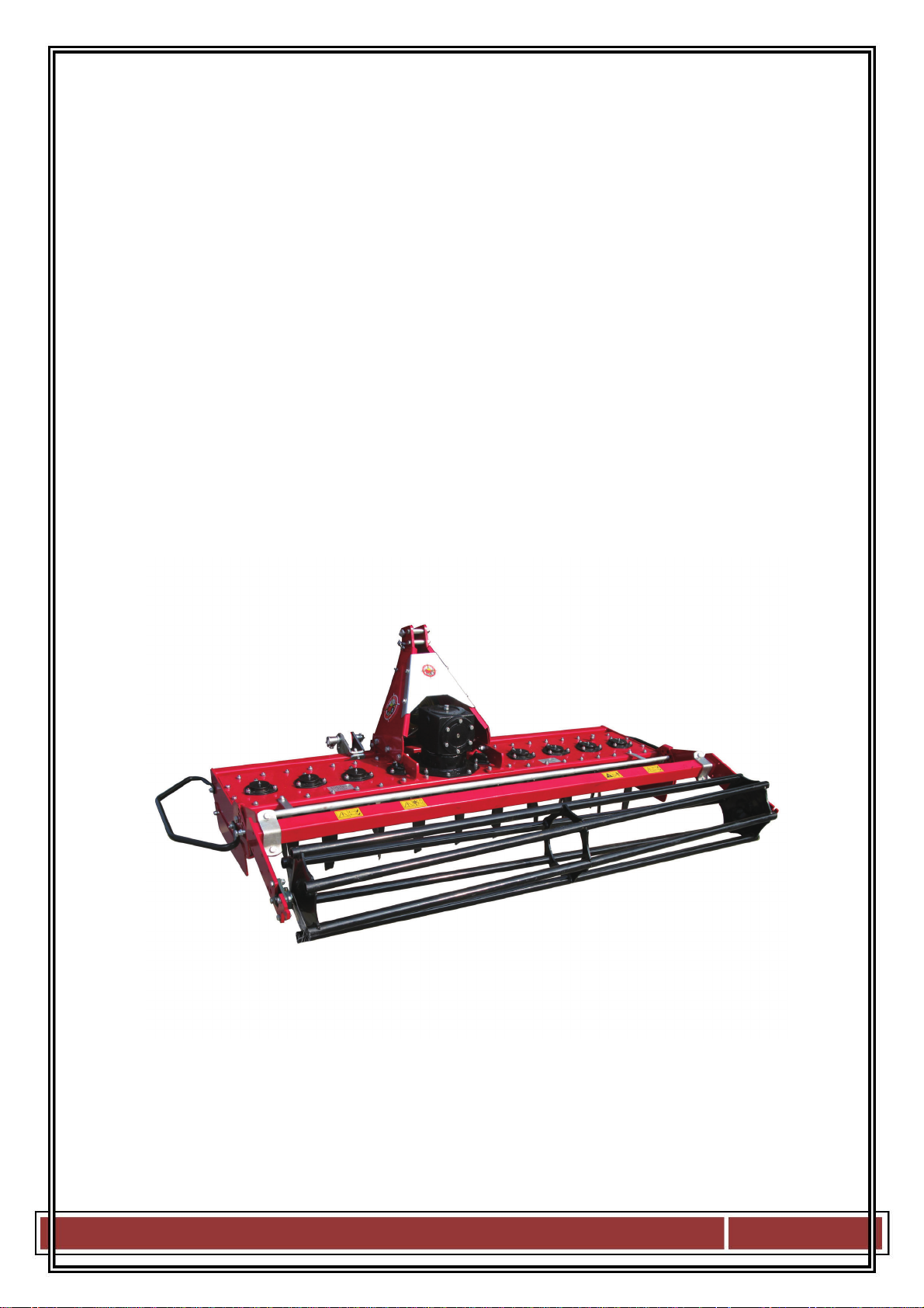
With its five tine units, the rotary power harrow type power harrow is an ideal implement for tilling
the soil and preparing seed-beds on farms and in vineyards or orchards, as well as for row crops and
specialty crops.
Please read these Operating Instructions through carefully before using the rotary power harrow and
strictly follow all the instructions so that the rotary harrow can be used safely and correctly, for its
intended purpose.
The power harrow may only be used by
p
e
r
so
n
s
who have the
required p
r
ofessio
na
l
know-how
and
who have also
read
and
understood
these
Operating
I
n
s
t
r
u
c
t
io
n
s.
Please ensure that you know how to handle and operate the power harrow before using it!
General i
n
fo
r
m
a
t
io
n
:
•
The rotar
yp
ower harrow ma
y
onl
y
be used for the s
p
ecified
p
ur
p
ose: mechanical soil
tillage and seed-bed preparation.
•
The power harrow may only be started and stopped from the tractor driver’s seat. No-
one may remain within a distance of less than 10 meters around the rotary harrow during
its operation.
•
The power harrow may only be operated in full daylight.
•
The power harrow may only be operated when all guards and safety mechanisms are
installed and fully functional.
•
Malfunctions impairing safety must immediately be remedied by specialist personnel.
•
The accident prevention regulations issued by the employers’ liability insurance association
must be observed.
•
The traffic regulations must be observed when driving on public roads.
•
ThePTOshaftmustbedisengagedfromthetractor during all maintenance and repair
work on the power harrow in order to prevent inadvertent start-up.
•
Repairs should only be undertaken by specialist repair shops or the customer service
center. The rotary power harrow should never be modified without authorization.
•
The power harrow may only be operated with a
PTO
shaft with
f
r
ic
t
io
n
cl
u
t
c
h
.
2

2. Desc
r
i
p
t
io
n
of the
m
a
c
h
i
n
e
:
The rotary power harrow must be used for mechanical soil tillage and seed-bed preparation on
farms and in vineyards and orchards, as well as for row crops and specialty crops.
Moisture remains in the soil and the water balance of the soil is maintained since the soil is not
turned up as it is tilled. The vertically rotating cutters also prevent compaction of the soil, thus
resulting in optimum preparation of the seed-beds.
The power harrow is mounted on the tractor by means of a three-point suspension. It has five tine
units; the tine pick-up is rigidly mounted. The gear mechanism is driven via a PTO shaft and drives
the cutters in the housing via gear wheels.
The working depth is set by means of a hand spindle in combination with the support roller. The
friction clutch mounted on the PTO shaft protects both the harrow and the tractor from damage if
overloaded. An additional machine, such as a seeder, can be connected to the rotary harrow via a
further three-point suspension on the basic unit and a p.t.o. shaft on the main gear unit. In this way,
the seed-bed can be prepared and the seed sown in a single pass.
The working depth should be adjusted in line with the prevailing ground conditions in order to
obtain the best possible results. Large objects should be removed from the ground beforehand so
that the soil can be tilled correctly and to prevent premature wear on the tines.
The housing accommodates the various components making up the rotary power harrow. The
support roller, three-point frame, angular gear and tine units are bolted onto the housing.
The
three-point frame
is made of robust sheet metal and bolted onto the housing. The bolts of the
lowe
r
links
support
can be undone and the three-point frame displaced sideways on the rectangular
profile of the housing for off-center operation.
The
angular gear
which is mounted on the housing diverts the tractor’s rotary motion through 90°
and drives the tine units via gear wheels.
Each tine unit comprises a tine flange, guard plate, two tines, bearing housing, bearing and
connecting elements. The tines are mounted underneath the guard plate and serve to loosen the soil.
They are secured by means of special bushings, washers, bolts and lock nuts.
3

3.
Start-up
and
operation
of
the
m
a
c
h
i
n
e
:
*Befo
r
e using the machine
for
the
first
t
i
m
e
- Read through the
operating instructions for
the rotary power harrow
and additional attachments
and ensure that you are fully
familiar with the mode of
operation of all units.
- Check that the length of
the PTO shaft fits your
tractor. The PTO shaft
should include an
appropriate protective
mechanism!
*
Attachment
to the
t
r
a
c
t
o
r
- Examine tools (tines)
and tine carriers for
signs of wear and
ensure they are
secured correctly.
- Check that the support roller
and three-point frame are
correctly secured to the housing.
- Now connect the
power harrow to the
tractor by means of
the three-point
suspension. Secure the
bolts of the upper and
lower links with
spring pins. Park the
tractor on level
ground and adjust the
upper link so that the
rotary power harrow is
horizontal.
- Now adjust the length of the
PTO shaft to match your
tractor. For this purpose,
hold
the two halves of the
PTO shaft side-by-
side in the shortest
lift-out position and
mark it accordingly.
Shorten the inner and
outer protective tube
by equal amounts.
Then shorten the
inner and outer
sliding profile by the
same amount as the
protective tube.
Finally round
off the
cut edges and
carefully remove all
chips. Grease the
sliding profiles.
- Before engaging the
PTO shaft, carefully
clean and grease the
p.t.o. shaft of the
tractor and power
harrow. Then slide
the PTO shaft over
the p.t.o. shaft until
the locking
pin
engages completely.
The friction clutch
of the PTO shaft
must be mounted at
the machine end.
-The
wo
r
k
i
n
g
depth
is now adjusted with
the aid of the hand
spindle in
accordance with
ground condition on
a firm and level
substrate or by
lifting the unit
completely.
The power harrow with
fitted tools and attachments
is now ready for use.
4

*
Working
with the
power
ha
rr
ow
- The tractor p.t.o. shaft must not be switched on until it is certain that the shaft will rotate
at not more than 540 rpm at maximum engine speed.
- The p.t.o. drive must not be engaged when the tractor drives running at full load.
-The
p
owe
r
harrow
may only be
started
and stopped
from
the
t
r
a
c
t
o
r
driver’s
se
a
t
.
- The power harrow may only be switched on when there is no-one within its range of
operation and hazard area (radius of 10 m from the rotary harrow) due to the risk of
objects,
such as
stones, being hurled away from the machine. The duly prepared machine
must be lowered to the working position before it is switched on. The rotary power
harrow can then be switched on.
- The machine must be lowered slowly in order to avoid damage to the tools and
attachments.
- During the work, the machine must be lowered to the working depth and left with the set
control hydraulics. The horizontal position of the rotary power harrow can be
corrected by
means of the upper link.
- The areas to be tilled should be inspected for visible large obstacles before staring so that
they can be removed from the harrow’s range and thus prevent damage to the tines and
drive elements.
- If a reversing manoeuvre is required at the end of the row being tilled, the tractor p.t.o.
must be switched off and the rotary harrow allowed to come to a complete standstill
before it is lifted out of the ground for the manoeuvre (risk of clods of earth being hurled
off by the tines).
- If the frame has been fully fitted with tools, its stability will be assured even without
support wheels.
- Dust clouds may form when operating the power harrow at higher speeds on dry ground.
Light respiratory protection should therefore be worn when using a tractor without
closed driver’s cab.
5

4.
Maintenance, care
and
t
r
an
s
p
o
r
t:
The
PTO
shaft must always be disengaged and the ignition key
r
e
m
ove
db
efo
r
es
t
a
r
t
i
n
g
any
maintenance
and
repair work
on the
power
ha
rr
ow!
Maintenance or repair work must never be performed underneath the rotary power harrow
without appropriate supports. Precautions must always be taken to prevent the machine from
dropping inadvertently, for instance by using hoisting gear.
The rotary power harrow should always be placed on firm, level ground.
The power harrow type LXG is designed and built to require as little maintenance and care as
possible.
H
oweve
r
,
the following points should be o
b
se
r
ve
dn
eve
r
t
h
eless
:
- All nuts, bolts and screws must be examined after the first five hours of operation and
then always before using the machine in order to ensure that they are secure.
They
must
be retightened if necessary.
- The PTO shaft must be lubricated with sufficient sulphur-free grease every eight hours
of operation so that it can always be extended and retracted without difficulty. The
bearing points on the cutter unit, the spindle for setting the working depth and the
roller mount must be lubricated every 30 hours of operation via the corresponding
grease nipples.
- The oil must be checked every 20 hours of operation.
- Gear oil must be changed after approx. 200 hours of operation. A container must be
placed under the machine to collect the escaping oil and prevent contamination of the
ground. Waste oil must be disposed of in accordance with the regulations.
- The rotary power harrow should be stored in a dry place, on firm, level ground. It
should be secured with chocks or similar objects to prevent inadvertent tilting.
- The machine must be thoroughly cleaned before prolonged storage. Those parts which
are in contact with the ground during operation should be sprayed with corrosion
inhibitor.
- Particular attention must be paid to the condition of the tines in order to ensure
maximum occupational safety and high-quality results. Before starting work, the tine
must therefore be examined to ensure they are correctly secured and wear down
evenly. Bent tines must be replaced immediately.
- Vibrations in the rotary power harrow are usually due to imbalances in the tine unit
and may damage the machine. Switch off the rotary power harrow and the tractor if
the vibrations increase significantly during operation or if the machine’s running noise
changes suddenly. The cause must be located and remedied before resuming work.
6

- When cleaning the machine with a high-pressure cleaner, care must be taken not to
direct the high-pressure jet against bearings and seals, as this can result in
malfunctions and premature failure of the machine.
- The screw connections between tines and tine flange / guard plate must be checked
regularly. Always fit new lock nuts and new washers whenever the screw connections
have been removed. The condition and degree of wear on the tines and tine pick-up
must be checked regularly.
- When transporting the machine, care must be taken to ensure that there is no one and
nothing in the immediate vicinity when sluing outwards with the tractor.
- The power harrow should only be repaired by a specialist repair shop or a authorized
customer service center.
Changing and
regrinding
t
i
n
es
:
Tines should only be
reground
and changed by
your dealer,
since
co
n
si
d
e
r
ab
le
hazards
c
an
arise
if they
are
fitted
i
n
co
rr
ec
t
ly.
Removal of the
t
i
n
es
:
- First switch off the tractor and remove the ignition key.
- Disengage the PTO shaft and then the rotary power harrow from the tractor.
Remember
to
support
it so that it cannot tip ove
r
i
nad
ve
r
t
e
n
t
ly.
- Turn the power harrow over with the aid of hoisting gear so that the tines can be
reached without difficulty.
- Remove the fastening bolt and nut with a suitable wrench.
•
Im
p
ortant:
For safet
y
reasons, new self-lockin
g
nuts and new washers must alwa
y
sbe
used whenever the tints are changed.
Ensure
that the tines
are
fitted co
rr
ec
t
ly
in the
direction
of
r
o
t
a
t
io
n
.
Installation
of the
t
i
n
es
:
- Fit the tines in the correct order.
- Fit the fastening bolt, washers and nut.
- Tighten the self-locking nut twice.
R
eg
r
i
nd
i
n
g
the
t
i
n
es
:
If the tines have to be reground, care must be taken to ensure that each pair of tines in the
tine unit is reground. This prevents the tine unit concerned becoming imbalanced.
Use the
transport
aids
or three-point
hitch
provided
on the housing to
transport
and
handle the
p
owe
r
ha
rr
ow.
7

5. Safety i
n
s
t
r
u
c
t
io
n
s
:
- The Implements may only be used when all safety mechanisms are in place and
fully functional.
- All faults capable of impairing safety must immediately be remedied by specialist
personnel.
- The operating instructions of any additional attachments installed must be read
through carefully and observed.
- Never climb onto the tractor or leave it unattended when the p.t.o. shaft is running.
- Never allow anyone who is not familiar with the safety and operating instructions to
use the machine.
- Remove all visible large objects which may be picked up and hurled aside by the
rotary power harrow. Particular attention must be paid to loose wires on the ground.
- Adjust your driving speed in line with the ground conditions and prevailing
circumstances.
- No one may remain within 10 meters of the power harrow during operation of the
machine. High
risk
of
injury
due to moving machine parts and objects being hurled
away from the machine, such as stones, etc.
- Never climb or reach in between the power harrow and the tractor with your arms or
legs during operation of the machine – high
risk
of
injury!
(This is only permitted
when the machine has been lowered to the ground and the tractor switched off.)
- The machine should only be operated in full daylight . Traffic regulations must be
observed when driving on public roads. Adequate illumination must be ensured when
driving in twilight or darkness (A detachable set of lights is recommended.)
- Never climb or reach in between the support roller and cutter unit with your arms or
legs – high
risk
of
i
n
j
u
r
y.
- Always wear tightly fitting clothes so that these cannot be caught between rotating
parts of the machine.
- Safety stickers must be kept clean and observed!
- Never open or remove the guard elements during operation. Worn or defective parts
must immediately be replaced by new parts.
8

- The cutter unit must never be operated when the power harrow is lifted off the ground.
- Driving a tractor on steep slopes can be dangerous. If work on steep slopes is
unavoidable, great care should be exercised. Do not take bends too tightly.
- No one may ever ride on the machine either during operations or while it is being
transported, not even over short distances.
- Always examine the rotary power harrow for signs of damage following a collision
with any objects. Such damage must always be repaired before resuming work.
- Maintenance and repair work may only be carried out when the PTO shaft and
machine have been disengaged form the tractor.
- Never crawl under a rotary power harrow which is still connected to the tractor, as the
machine may be lowered at any time – high
risk
of
i
n
j
u
r
y.
- The accident prevention regulations of the employers’ liability insurance association
must be observed when using the machine.
- When traveling round bends, take account of the larger width / length (turning circle)
and considerable weight of the rotary power harrow.
- Ensure that the PTO shaft halves and protective tubes overlap as prescribed, both in
the transport position and in the working position. Read the operating instructions for
the PTO shaft in this context.
- The PTO shaft should only be engaged and disengaged when the tractor engine is
switched off and the ignition key has been removed.
9
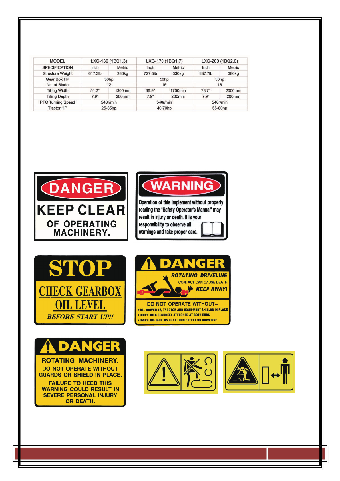
6. Technical data
:
7. Safety Decals
:
10
11

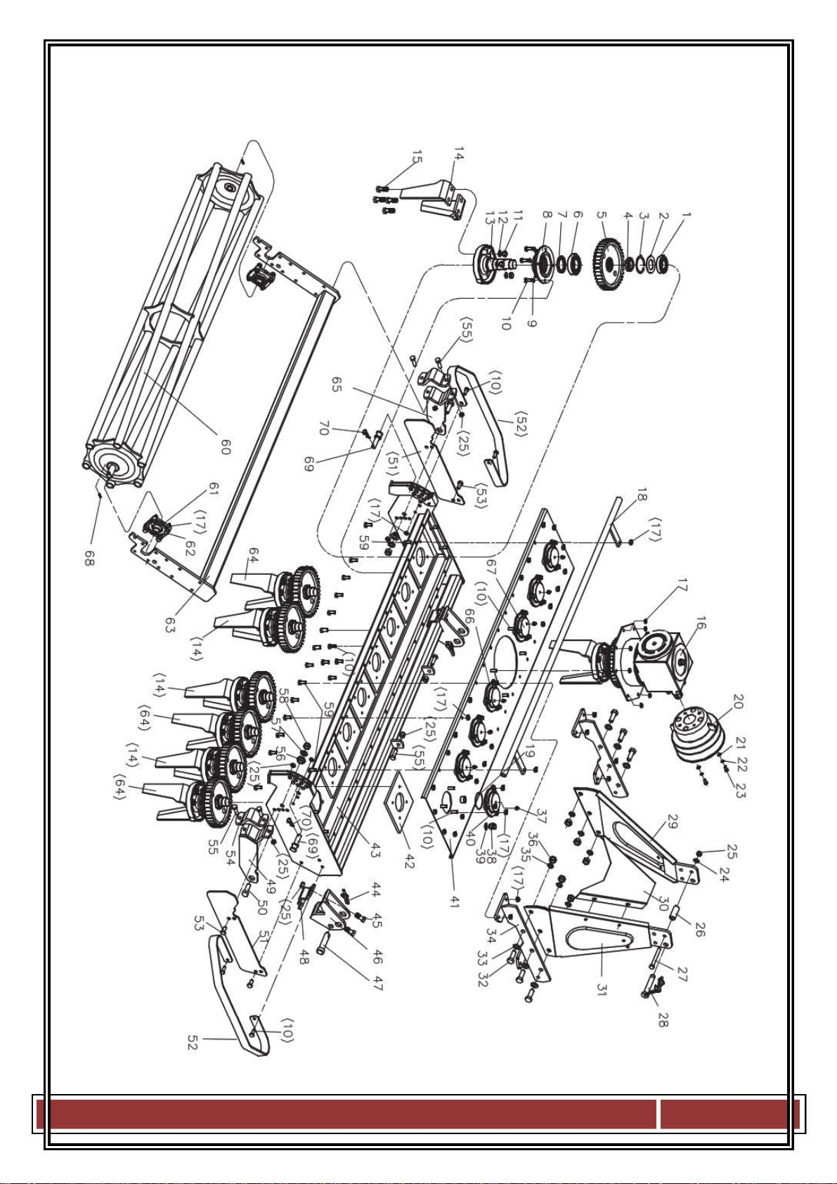
NO.
Part NO. Name & Specifications Quantity
Remark
1 GB276-6207 511022613
Bearing 6207 7
2 LXG170.115 706590024
Big washer 7
3 GB893.1-72 506060188
Seeger ring 72 7
4 LXG170.116-1 706590025
Self locking nut M39x1.5 7
5 LXG170.118 706590026
Export gear 7
6 GB276-6209 511022615
Bearing 6209 7
7 GB13871-FB-50X68X10
510020641
Oil seal FB -50X68X10 7
8 LXG170.112 706590023
Rotor support down panel 7
9 GB93-10 506030036
Washer 10 32
10 GB5783-M10X35 501011114
Bolt M10 x 35 32
11 GB6170-M14 503010048
Nut M14 32
12 GB93-14 506030038
Washer 14 32
13 LXG170.110 706590022
Colter fixing seat 7
14 LXG170.109 706590021
Colter 8
15 GB5782-M14X60 501010768
Bolt M14x60 32
16 LXG130.011 805680006
Gear case assembly 1
17 DIN985-M10 503010762
Six corner locknut M10 77
18 LXG130.018-1 805680002
Staff guage jointing 1 LXG130
LXG170.018-1 806590006
Staff guage jointing 2 LXG170
LXG210.018-1 805700003
Staff guage jointing 3 LXG210
19 GB3452.1-G-90X3.55 510013257
O-ring 1
20 FM120.00.199 703400008
PTO shaft cover 1
21 GB97.1-8 506010055
Washer 8 2
22 GB93-8 506030035
Washer 8 2
23 GB5783-M8X16 501011098
Bolt M8x16 2
24 GB97.1-12 506010057
Washer 12 2
25 DIN985-M12 503010763
Six corner locknut M12 2
26 MZ105.130 703140006
Bushing 2
27 GB5782-M12X100 501010763
Bolt M12x100 2
28 EF100.00.019-1 703740002
Above append pin 1
29 LXG170.029 806590014
Sx 3rd point 1
30 LXG170.104 706590017
Reinforcement 1
31 LXG170.028 806590013
Dx 3rd point 1
32 GB5782-M16X45 501014760
Bolt M16x45 6
33 GB97.1-16 506010059
Washer 16 6
34 LXG170.012 806590002
Impendend connect fixing
jointing 2
35 GB93-16 506030039
Washer 16 6
36 GB6170-M16 503010049
Nut M16 6
37 GB1152-M10X1 509010009
Frank press oiling cup M10x1
8
38 CBW-00-011 703070084
Aerate bolt discreteness 2
39 JB982-16 510015240
Combined oil seal 16 2
12

NO.
Part NO. Name & Specifications Quantity
Remark
40 LXG170.102 706590015
Rotor support above panel 6
41 LXG130.015 805680001
Above cover boart jointing 1 LXG130
LXG170.015 806590003
Above cover boart jointing 1 LXG170
LXG210.015 805700001
Above cover boart jointing 1 LXG210
42 LXG170.132 706590034
Mat 8
43 LXG170.016 806590004
Engine rack jointing 1
44 200.56.011 700080010
Snap pin chain 2
45 GB5783-M12X40 501011128
Bolt M12x40 4
46 LXG170.130 706590032
Stirrup 2
47 LXG170.106 706590019
Pin 2
48 LXG170.131 706590033
Stirrup 2
49 LXG170.021 806590007
Unknit rack right connect
jointing 1
50 GB5783-M16X45 501011159
Bolt M16x45 2
51 LXG170.122 706590027
Shield 2
52 LXG170.101 706590014
Shield rack 2
53 GB5783-M12X30 501011126
Bolt M12x30 4
54 RT150.107 706590008
U bolt 2
55 GB5783-M12X40 501011128
Six corner bolt 18
56 LXG170.108 706590020
Bush 2
57 GB97.1-16 506010059
Washer 16 2
58 DIN985-M16 503010765
Six corner locknut M16 2
59 GB5783-M10X30 501011113
Bolt M10x30 10
60 LXG130.024 805680003
Unlnit implement jointing 1 LXG130
LXG170.024 806590008
Unlnit implement jointing 1 LXG170
LXG210.024 805700004
Unlnit implement jointing 1 LXG210
61 UCF205 511040011
Squareness bearing UCF205 2
62 GB5783-M10X40 501011115
Bolt M10x40 8
63 LXG130.025 805680004
Unlnit implement connect
rack jointing 1 LXG130
LXG170.025 806590011
Unlnit implement connect
rack jointing 1 LXG170
LXG210.025 805700005
Unlnit implement connect
rack jointing 1 LXG210
64 LXG170.123 706590028
Colter 8
65 LXG170.017 806590005
Unknit rack left connect
jointing 1
66 LXG170.102 706590015
Rotor support above panel 1
67 LXG170.102 706590015
Rotor support above panel 1
68 GB879.1-8X35 508011565
pin 8x36 2
69 LXG170.250 706590072
pin 2
70 ZL-25.104 703340017
pin 2
13
14

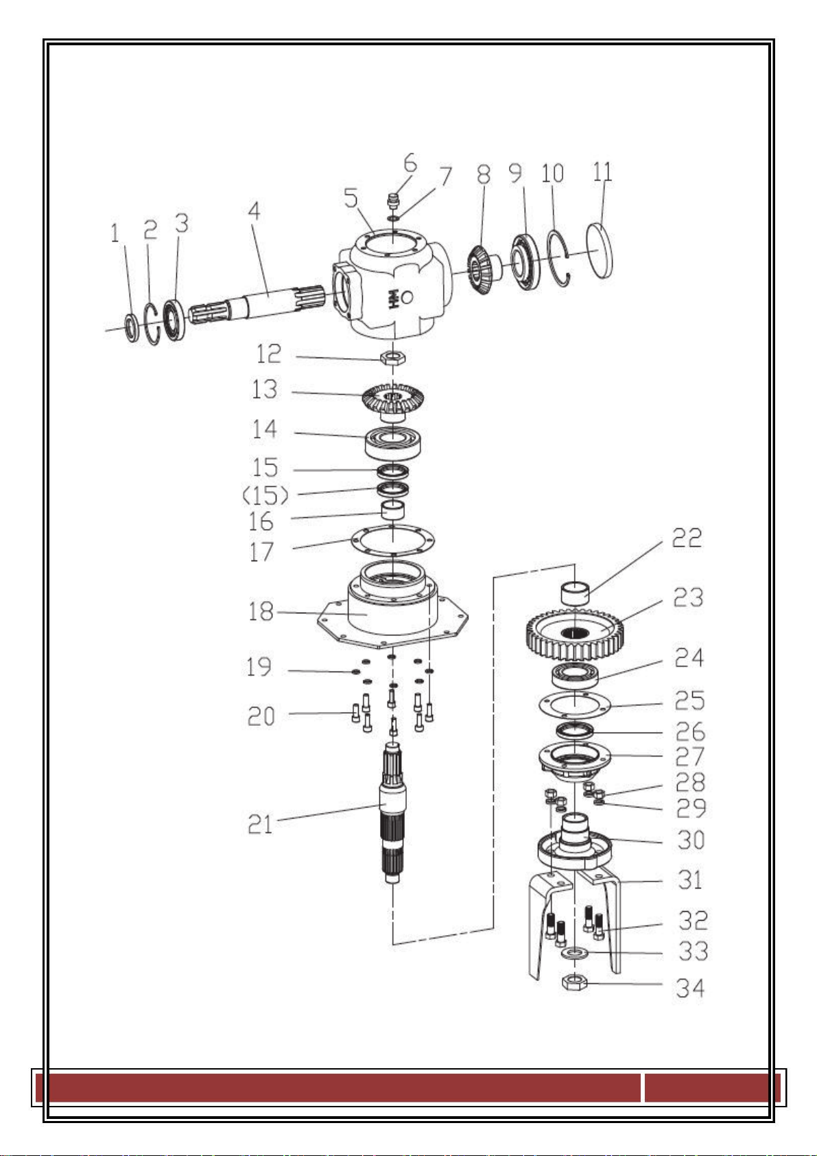
NO. Part NO. Name & Specifications Quantity
Remark
1 CFW-40X80X12 510020412
Oil seal 40X80X12 1
2 GB893.1-80 506060191
Seeger ring 80 1
3 GB297-30208 511016412
Bearing 30208 1
4 1G-150.01.117-1 703190197
Transmission shaft 1
5 1G-150.01.118 703190198
Gearbox 1
6 CBW-00-011 703070084
Breather plug 1
7 JB982-16 510015240
Combined oil seal 16 2
8 1GN180.00.141 703210001
Smallcone-shaped gear 1
9 GB297-30310 511016492
Bearing 30310 1
10 GB893.1-110 506060203
Seeger ring 110 1
11 NFG-RCA-110X12 706230018
Back end cover 1
12 GB812-M30X1.5 503020071
Lock Nut M30x1.5 1
13 1GN180.00.146 703210002
Big cone-shaped gear 1
14 GB276-6311 511022658
Bearing 6311 1
15 CFW-50X68X8 510020390
Oil seal 50x68x8 2
16 LXG170.138 706590038
Bushing 1
17 1G-150.01.114 706590011
Casket 1
18 LXG170.026 806590012
Setting 1
19 GB93-10 506030036
Washer 10 8
20 GB70.1-M10X25 505011429
Bolt M10x25 8
21 LXG170.136 706590037
Output axles 1
22 LXG170.135 706590036
Bushing 1
23 LXG170.133 706590035
Output gear 1
24 GB276-6211 511022617
Bearing 6211 1
25 LXG170.128 706590031
Gasket 8
26 GB13871-FB-60X80X10 510020634
Oil seal PB-60X80X10 1
27 LXG170.147 706590039
Bearing seat 1
28 GB6170-M14 503010048
Nut M14 32
29 GB93-14 506030038
Washer 14 32
30 LXG170.126 706590030
Colter setting seat 1
31 LXG170.123 706590028
Colter 8
32 GB5783-M14X40 501011142
Bolt M14x40 32
33 LXG170.125 706590029
Washer 30 1
34 GB812-M30X1.5 503020071
Lock Nut M30x1.5 1
15

16
This manual suits for next models
8
Table of contents
Popular Farm Equipment manuals by other brands

Schaffert
Schaffert Rebounder Mounting instructions

Stocks AG
Stocks AG Fan Jet Pro Plus 65 Original Operating Manual and parts list

Cumberland
Cumberland Integra Feed-Link Installation and operation manual

BROWN
BROWN BDHP-1250 Owner's/operator's manual

Molon
Molon BCS operating instructions

Vaderstad
Vaderstad Rapid Series instructions


