Hanna Instruments HI2004-18 User manual

INSTRUCTION MANUAL
Hanna Instruments Inc., 584 Park East Drive, Woonsocket, RI 02895 USA www.hannainst.com
HI2004-18 • HI2004-28
HI2014-18 • HI2014-28
HI510 Compatible
ORP and Temperature
Industrial Smart Probes
SN: XXXXXXXXXXXX
ORP: ± 2000 mV
T: −5 to 100 °C
pmax: 6 bar
HI2004-1805
SN: XXXXXXXXXXXX
ORP: ± 2000 mV
T: −5 to 100 °C
pmax: 6 bar
SN: XXXXXXXXXXXX
ORP: ± 2000 mV
T: −5 to 100 °C
pmax: 6 bar
HI2004-1800
Please scan the QR code or follow the link
to download the HI510 controller user manual.
https://manuals.hannainst.com/HI510
Hanna®is committed to developing and deploying digital solutions
with a positive impact on the environment and climate.

All rights are reserved. Reproduction in whole or in part is prohibited without the written consent of the copyright owner,
Hanna Instruments Inc., Woonsocket, Rhode Island, 02895, USA.
Hanna Instruments reserves the right to modify the design, construction, or appearance of its products without advance notice.
TABLE OF CONTENTS
1. Preliminary Examination ................................................................................................................3
2. Safety Measures............................................................................................................................3
3. General Description & Intended Use ................................................................................................3
4. Main Features...............................................................................................................................4
5. Series Configuration.......................................................................................................................4
6. Specifications................................................................................................................................5
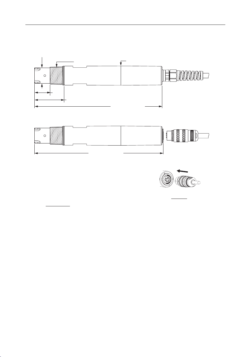
7. Probe Dimensions & Cable Connection.............................................................................................6
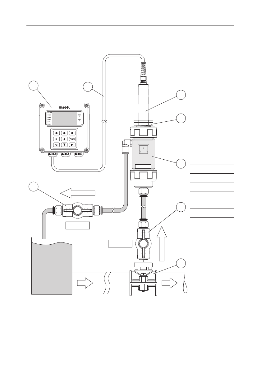
8. Installation ...................................................................................................................................6
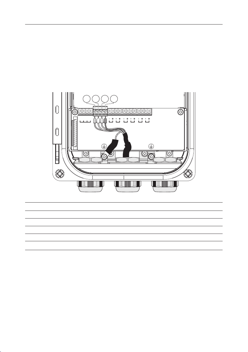
9. Wiring the Probe to the Controller..................................................................................................10
10. Calibration................................................................................................................................10
11. Maintenance & Conditioning.......................................................................................................11
12. Accessories................................................................................................................................12
13. Abbreviations............................................................................................................................13
Certification......................................................................................................................................14
Recommendations for Users...............................................................................................................14
Warranty .........................................................................................................................................14
Dear Customer,
Thank you for choosing a Hanna Instruments®product.
Please read this instruction manual carefully before using this instrument as it provides the necessary information
for correct use of this instrument as well as a precise idea of its versatility.
This release of the product manual contains information that applies to configuration, specification, installation,
and calibration of Hanna Instruments industrial ORP probes.
The HI510 controller is sold separately. Please refer to the controller manual for details on system configurations.
Visit www.hannainst.com for more information about Hanna Instruments and our products.

3 Preliminary Examination
1. PRELIMINARY EXAMINATION
Remove the probe from the packing and examine it carefully.
Remove the sensor's protective cap before use.
Each probe is supplied with quick reference guide with probe quality certificate.
Note: Save all packing material until you are sure that the probe works correctly. Any damaged or defective item
must be returned in its original packing material with the supplied accessories.
2. SAFETY MEASURES
General Safety & Installation Recommendations
•
Electrical connection, installation, operation, and maintenance must be carried out by specialized
personnel only.
The specialized personnel must read, understand, and adhere to the instructions in this manual.
•
Before connecting the probe to the process controller, disconnect the controller from the power line.
• User serviceable connections are all accessible inside controller’s enclosure.
• Before powering the controller, verify the probe wiring has been done following the instructions
detailed in this manual.
3. GENERAL DESCRIPTION & INTENDED USE
HI20X4-18 and HI20X4-28 are ORP and temperature probes designed for use with the Hanna Instruments®
HI510 Universal Process Controller. The system is designed to monitor and control disinfection chemicals or
follow and control a critical oxidation (or reduction) reaction.
mV measurements are auto-compensated for barometric pressure and temperature.
HI2004-18 and HI2014-18 platinum-sensor series are designed to provide the best response over a wide
range of applications.
HI2004-28 and HI2014-28 gold-sensor series are designed for oxidative processes.
The probe features a flat tip (ideal for solutions containing aggressive chemicals) which virtually eliminates dirt
deposits and significantly reduces maintenance.
Suitable for continuous measurement of ORP required for monitoring ond/or controlling oxidizers and reducing
agents in water treatment monitoring, industrial effluent treatment, and swimming pools, the probe can be
submersed/immersed using the 3/4” NPT threads, or installed directly in-line or in a flow cell installation, using
the lower sensor threads.
The probe is available with an integral connector that permits connections with no twisted cables as cables
are connected after installation.
Patch cables may be purchased separately to connect between the probe and controller up to 50 meters (164 ft).

Main Features 4
4. MAIN FEATURES
• Rugged, chemically-resistant PVDF body
• 3/4” NPT external thread
• 6 bar (87 psi) maximum pressure at 25 °C (77 °F)
• Built-in temperature sensor for measurement
• Digital probe stores model, firmware, serial number, and calibration information
• Minimum maintenance
5. SERIES CONFIGURATION
HI20 x x –y8z z
xx 04 PTFE junction
14 Ceramic junction
y
1
Platinum sensor
–5.0 to 100.0 °C (23.0 to 212.0 °F)
± 2000 mV
2
Gold sensor
–5.0 to 100.0 °C (23.0 to 212.0 °F)
± 2000 mV
8Smart probe with RS485 connection
zz 00 supplied with DIN connector (without cable). See Accessories section for patch cable ordering codes.
05, 10, 15, 25, 50 fixed cable length (in meters)
PTFE junction
Minimizing the potential for clogging and chemically resistant, PTFE is ideal for samples with high
content of suspended solids or for high-pressure installations.
Ceramic junction
Porous, chemically resistant plug connects the reference electrode to the process electrically.
Platinum sensor
Used in reducing processes e.g. chlorine dosing in pools and spas, or chromate reduction.
Gold sensor
Used in oxidative processes e.g. cyanide oxidation in the mining industry.

5 Specications
6. SPECIFICATIONS
HI2004-18zz
Range –2000 to +2000 mV
Resolution 1 mV
Accuracy ± 2 mV
Calibration Single point, value can be adjusted ±60 mV around measured mV
Temperature
Range –5.0 to 100.0 °C (23.0 to 212.0 °F)
Resolution 0.1 °C; 0.1 °F
Accuracy ± 0.5 °C; 1.0 °F
Calibration Single point offset (controller setting)
Temperature source Automatic (from Probe)
Manual
Body PVDF
Junction PTFE
Sensor
Material Platinum
Body Glass
Tip shape Flat
Diameter 22 mm (0.9")
Insertion length 21 mm (0.8")
Maximum pressure 6 bar
Threaded connection 3/4” NPT external thread for mounting
Wetted parts
Probe body PVDF
Sensor body Glass
O-ring NBR
Junction PTFE
Matching pin Titanium
Protection rating IP68
Cable length zz , see Series Configuration

Probe Dimensions & Cable Connection 6
7. PROBE DIMENSIONS & CABLE CONNECTION
43 mm (1.7")
21 mm (0.8")
Ø 28 mm (1.1”)
Ø 22 mm (0.9”)
3/4’’ NPT
185 mm (7.3”)
187 mm (7.4”)
Align the pins and key then push the plug into the socket.
Rotate the collar to lock in place.
Note: Connecting (probe with integral DIN connector) or wiring a new probe must be carried out with the
instrument disconnected from power.
8. INSTALLATION
General considerations
• Probes are easily installed using the 3/4” NPT external threads.
• Do not install the probe in an upside-down position.
•
Hand tighten the probe in position. Then, depending on the process, tighten one or two turns with a
wrench to secure in place. Do not exceed 10 N•m (7.3 lb-ft) torque specification for the probe sensor.
• Protect the probe from strong flow to prevent unstable readings.
• Protect the sensing surface from blunt objects.
• Make sure the sensing surface is kept clean.
• Provisions must be made for the removal of the probe from the process.
• Consider probe accessibility for maintenance when selecting placement.

7 Installation
Typical installation examples with mounting accessories
Accessories are sold separately.
In-line mounting and flow-cell installation require that the saddle and flow cell are completely filled with water.
In-line mounting with probe saddle
1
2
4
3
5
Note: Probe can be rotated to prevent air entrapment inside the electrode.
Mounting accessories
Pipe size Saddle code HI20xx-Y8zz
Ø 50 mm (2”) BL120-550
Ø 63 mm (2½”) BL120-563
Ø 75 mm (3”) BL120-575
1 Probe
2 Probe fitting kit
3 Saddle
4 Sensor tip
5 Pipe

Installation 8
Tank immersion with submersible electrode holder
I
II
III
1
2
4
3
5
6
7
9
8
The HI60501/HI60503 (PVC/PVDF submersible holders) and HI605011 (mounting flange) provide a sturdy
housing that prevents the probe from being damaged.
For high-temperature/complex chemical processes it is recommended the use of PVDF accessories.
To install the probe:
A. Unscrew the protective end cap (9).
The removable end cap allows for quick and simple probe maintenance and replacement.
B. Slide out the electrode holder cap (3).
C. Screw the probe into the internally threaded protective cap (9), step I.
D. Screw the probe and protective cap subassembly onto the holder (5), step II.
E. Feed the probe cable through the holder (5) and out through the cap (3) and cable gland on top (2).
The cable is shielded inside the holder to prevent any damage to the insulation.
F. Tighten the cable gland (2), step III, and slide the cap (3) back onto the holder (5).
1 Probe cable
2 Cable gland
3 Electrode holder cap
4 Adjustable immersion level
5 Electrode holder
6 Probe body
7 O-ring, Ø 22.2 mm (0.87”)
8 Sensor tip
9 Protective end cap

9 Installation
Flow-cell installation
Do not allow deposits of sediment or other foreign material to accumulate within the sensing area.
TANK
VALVE 1
VALVE 2
FLOWFLOW
INCOMING FLOW
EXIT FLOW
3
12
4
5
7
6
6
FLOW CELL
1 Process controller
2 Wiring cable
3 ORP probe
4 Flow-cell adapter
5 Flow cell
6 Flow-cell valves
7 Saddle

Wiring the Probe to the Controller 10
9. WIRING THE PROBE TO THE CONTROLLER
1. With the controller disconnected from power, run the probe cable through the conduit opening.
2. Connect the probe leads to the removable terminal connector marked PROBE. Follow the lead markings
(+) positive / (–) negative to ensure correct wiring position for the output leads.
3. Carefully put the wired terminal connector into place on the board.
4. Position the excess cable through the cable gland before tightening the nut.
5.
Remove the ground screw and hardware located below the PROBE connector and attach ground lead ( g).
COMM
-BA+
IN1 IN2 A01 A02 A03 A04
PROBE
-BA+
PROBE
-BA+
A+
B
—
Probe cabling color code
Marking Attached cable Patch cable * Functionality
– GREEN BLACK 0V
B WHITE WHITE RS485 D –
A YELLOW BLUE RS485 D+
+ BROWN RED 5V
gGREEN-YELLOW Protective ground connection
* See Accessories section for cable ordering codes.
Note: Ensure wiring regulations are correctly followed when controller unit is part of a larger industrial installation.
10. CALIBRATION
ORP calibration is a single point calibration performed with the probe installed in the process or with the
probe removed from the process. Calibration point value can be adjusted ±60 mV around the measured mV.
Preparation
Probe removed from process
• Rinse the probe with deionized water and pat it dry with a lint-free cloth prior to calibration.
• Submerge the electrode tip (4 cm/1½”) into the sample to be tested.

11 Maintenance & Conditioning
• Do not let the probe touch the bottom or sides of the container.
• Remove the air bubbles from under the probe tip. Stir the sample at a slow to moderate rate and wait a
few seconds for the reading to stabilize.
Note: ORP calibration standards may be used with the probe directly i.e. 240 mV (HI7021 ORP test solution for
platinum and gold electrodes) or 470 mV (HI7022 ORP test solution for platinum and gold electrodes).
Probe installed in process
• Use a calibrated reference ORP meter and probe to determine the process value and write it down.
Note: mV measurements generated by the ORP probe are displayed with 1 mV resolution.
Procedure
1. Press the m key.
2. When the controller is in mV measurement mode, press CAL virtual key.
3. Use the ud keys to adjust the value.
4. After the reading has stabilized and the mV offset is inside the offset window, CFM is displayed.
5. Press CFM key to confirm and save the ORP calibration.
11. MAINTENANCE & CONDITIONING
General Maintenance
• Inspect, clean, and calibrate the probe at regular intervals.
• Inspect all connectors for corrosion and replace if necessary.
• Inspect the cable. The connection cable must be intact.
• Calibrate the probe after prolonged storage or cleaning.
• After use rinse the probe with tap water and dry it.
Conditioning
• Remove the protective cap.
• Shake down the probe to eliminate any air bubbles inside the glass bulb.
•
If the bulb and/or junction are dry, soak the electrode in HI70300 Storage solution for at least 30 minutes.
•
To ensure a quick response time, the glass bulb and the junction should be kept moist and not allowed to dry.
Install the probe in such a way that it is constantly in the flow cell or the pipe is filled with the sample.
This will ensure a quick response and will keep the junction moist.
Cleaning
New probe
• Remove the protective cap.
• Rinse off salt deposits with water.
Probe removed from process
1.
Rinse the sensor in flowing water then clean by soaking in HI7061 Electrode cleaning solution for general
use for 15 minutes or use an application-specific cleaning solution.
2. Rinse with water and soak in HI70300 Storage solution for at least 30 minutes before reinstalling it.
3. Calibrate before use.

Accessories 12
In case of errors or faulty/fluctuating readings, gently polish the metal tip with a lightly abrasive paper, paying
attention not to scratch the surface. Follow with a thorough wash with water.
Storage
• When the probe is removed from the process for more than 1 hour, fill the protective cap with HI70300
Storage solution and tighten the cap on the sensor. Do not store the probe in distilled or deionized water.
12. ACCESSORIES
Ordering Information Product Description
ORP Solutions
HI7021M or HI7021L ORP test solution, 240 mV, 230 or 500 mL
HI7022M or HI7022L ORP test solution, 470 mV, 230 or 500 mL
HI7091L Pretreatment reducing solution, 500 mL
HI7092M or HI7092L Pretreatment oxidizing solution, 230 or 500 mL
Electrode Storage Solutions
HI70300M or HI70300L Storage solution, 230 or 500 mL
HI7082 3.5M KCl Electrolyte solution, 4x30 mL
Electrode Cleaning Solutions
HI7061M or HI7061L General cleaning solution, 230 or 500 mL
HI7073M or HI7073L Protein cleaning solution, 230 or 500 mL
HI7074M or HI7074L Inorganic cleaning solution, 230 or 500 mL
HI7077M or HI7077L Oil and fat cleaning solution, 230 or 500 mL
Other Accessories
HI60501 PVC immersion electrode holder
HI60503 PVDF immersion electrode holder
HI60501-0 O-rings for HI60501 electrode holder
HI605011 PVC mounting flange
HI60542 In-line electrode holder, direct pipe installation
HI76510-05 Patch cable, 5 m (16’5”)
HI76510-10 Patch cable, 10 m (32’9”)
HI76510-15 Patch cable, 15 m (49’2”)
HI76510-25 Patch cable, 25 m (82’)
HI76510-50 Patch cable, 50 m (164’)
BL120-400 Flow-cell probe adapter kit
BL120-401 Flow-cell valve

13 Abbreviations
Ordering Information Product Description
BL120-402 Flow-cell tubing,10 m (32’9”)
BL120-410 Flow cell
BL120-450 Flow-cell kit for Ø 50 mm (2”) pipe
BL120-463 Flow-cell kit for Ø 63 mm (2.5”) pipe
BL120-475 Flow-cell kit for Ø 75 mm (3”) pipe
BL120-500 Probe fitting kit
BL120-550 Probe saddle for Ø 50 mm (2”) pipe, 1 ¼” thread
BL120-563 Probe saddle for Ø 63 mm (2.5”) pipe, 1 ¼” thread
BL120-575 Probe saddle for Ø 75 mm (3”) pipe, 1 ¼” thread
For additional accessories information contact your local sales office.
13. ABBREVIATIONS
NBR Nitrile Butadiene Rubber
NPT American National Pipe Standard Taper Pipe Thread
PTFE Polytetrafluoroethylene
PVC Polyvinyl Chloride
PVDF Polyvinylidene Fluoride

Certication 14
CERTIFICATION
All Hanna®instruments conform to the CE European Directives.
Disposal of Electrical & Electronic Equipment. The product should not be treated as household waste. Instead,
hand it over to the appropriate collection point for the recycling of electrical and electronic equipment, which
will conserve natural resources. Ensuring proper product disposal prevents potential negative consequences
for the environment and human health.
For more information, contact your city, your local household waste disposal service, or the place of purchase.
RECOMMENDATIONS FOR USERS
Before using this product, make sure it is entirely suitable for your specific application and for the environment
in which it is used. Any variation introduced by the user to the supplied equipment may degrade its performance.
Do not use or store the product in hazardous environments.
WARRANTY
The probes are warrantied for six months against defects in workmanship and materials when used for its
intended purpose and maintained according to instructions. This warranty is limited to repair or replacement
free of charge. Damage due to accidents, misuse, tampering, or lack of prescribed maintenance is not covered.
If service is required, contact your local Hanna Instruments
®
office. If under warranty, report the model number,
date of purchase, serial number, and the nature of the problem. If the repair is not covered by the warranty, you
will be notified of the charges incurred. If the instrument is to be returned to Hanna Instruments, first obtain
a Returned Goods Authorization (RGA) number from the Technical Service department and then send it with
shipping costs prepaid. When shipping any product, make sure it is shipped back in compliance with shipping
regulations, thoroughly cleaned and free of any chemicals, and is properly packaged for complete protection.
MAN20X4-8 07/22
This manual suits for next models
3
Table of contents
Other Hanna Instruments Accessories manuals