manuals.online logo
Brands
  1. Home
  2. •
  3. Brands
  4. •
  5. Hans Grohe
  6. •
  7. Plumbing Product
  8. •
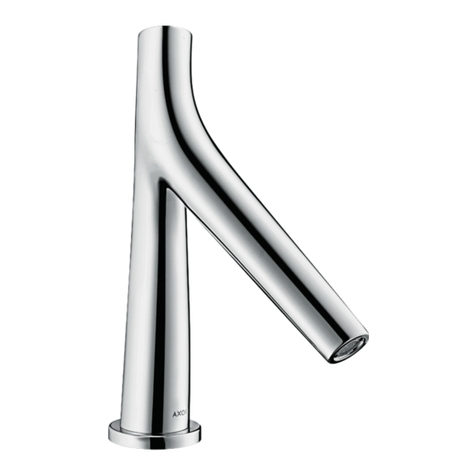
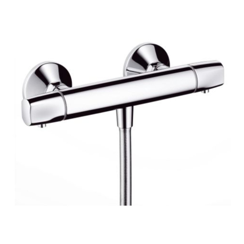
  9. Hans Grohe AXOR Starck 10754180 User manual

Hans Grohe AXOR Starck 10754180 User manual

Other Hans Grohe Plumbing Product manuals
Hans Grohe AXOR Citterio M 34132000 Manual

Hans Grohe

Hans Grohe AXOR Citterio M 34132000 Manual

Hans Grohe PuraVida 15775 1 Series Installation guide

Hans Grohe

Hans Grohe PuraVida 15775 1 Series Installation guide

Hans Grohe Vernis Shape 70 71566000 Manual

Hans Grohe

Hans Grohe Vernis Shape 70 71566000 Manual

Hans Grohe sBox 28016000 User manual

Hans Grohe

Hans Grohe sBox 28016000 User manual

Hans Grohe Crometta S 240 1jet Showerpipe 27269000 Manual

Hans Grohe

Hans Grohe Crometta S 240 1jet Showerpipe 27269000 Manual

Hans Grohe Montreux 16583 1 Series Instruction Manual

Hans Grohe

Hans Grohe Montreux 16583 1 Series Instruction Manual

Hans Grohe Novus 71140000 Manual

Hans Grohe

Hans Grohe Novus 71140000 Manual

Hans Grohe AXOR Starck 10020 Series User manual

Hans Grohe

Hans Grohe AXOR Starck 10020 Series User manual

Hans Grohe Talis S2 Variarc 14875 Series User manual

Hans Grohe

Hans Grohe Talis S2 Variarc 14875 Series User manual

Hans Grohe Crometta 100 Multi 26823400 User manual

Hans Grohe

Hans Grohe Crometta 100 Multi 26823400 User manual

Hans Grohe AXOR Starck V 12112 Series Manual

Hans Grohe

Hans Grohe AXOR Starck V 12112 Series Manual

Hans Grohe Vivenis 75200 1 Series Instruction Manual

Hans Grohe

Hans Grohe Vivenis 75200 1 Series Instruction Manual

Hans Grohe E 04060 0 Series Instruction Manual

Hans Grohe

Hans Grohe E 04060 0 Series Instruction Manual

Hans Grohe Raindance E 27380000 Manual

Hans Grohe

Hans Grohe Raindance E 27380000 Manual

Hans Grohe Vernis Blend Pressure Balance Shower Set 04952 0... User manual

Hans Grohe

Hans Grohe Vernis Blend Pressure Balance Shower Set 04952 0... User manual

Hans Grohe Ecostat 1001 CL 13213000 Manual

Hans Grohe

Hans Grohe Ecostat 1001 CL 13213000 Manual

Hans Grohe Rainfinity 250 1jet 26226 Series Manual

Hans Grohe

Hans Grohe Rainfinity 250 1jet 26226 Series Manual

Hans Grohe Fixfit S User manual

Hans Grohe

Hans Grohe Fixfit S User manual

Hans Grohe Raindance S 27636 0 Series Instruction Manual

Hans Grohe

Hans Grohe Raindance S 27636 0 Series Instruction Manual

Hans Grohe Talis C 04216 0 Series Instruction Manual

Hans Grohe

Hans Grohe Talis C 04216 0 Series Instruction Manual

Hans Grohe Axor Starck 10010 Series User manual

Hans Grohe

Hans Grohe Axor Starck 10010 Series User manual

Hans Grohe Metris 31480 Series Manual

Hans Grohe

Hans Grohe Metris 31480 Series Manual

Hans Grohe Metris Classic 15753 Series Manual

Hans Grohe

Hans Grohe Metris Classic 15753 Series Manual

Hans Grohe Axor Carlton 17670 Series User manual

Hans Grohe

Hans Grohe Axor Carlton 17670 Series User manual

Popular Plumbing Product manuals by other brands

Moen SANI-STREAM 8797 manual

Moen

Moen SANI-STREAM 8797 manual

Grohe Allure Brilliant 19 784 manual

Grohe

Grohe Allure Brilliant 19 784 manual

Cistermiser Easyflush EVO 1.5 manual

Cistermiser

Cistermiser Easyflush EVO 1.5 manual

Kohler Triton Rite-Temp K-T6910-2A installation guide

Kohler

Kohler Triton Rite-Temp K-T6910-2A installation guide

BEMIS FNOTAB100 Installation instruction

BEMIS

BEMIS FNOTAB100 Installation instruction

Akw Stone Wash Basin Installation instructions manual

Akw

Akw Stone Wash Basin Installation instructions manual

Enlighten Sauna Rustic-4 user manual

Enlighten Sauna

Enlighten Sauna Rustic-4 user manual

Moen ShowHouse S244 Series quick start guide

Moen

Moen ShowHouse S244 Series quick start guide

Sanela SLWN 08 Mounting instructions

Sanela

Sanela SLWN 08 Mounting instructions

Franke 7612982239618 operating instructions

Franke

Franke 7612982239618 operating instructions

Heritage Bathrooms Granley Deco PGDW02 Fitting Instructions & Contents List

Heritage Bathrooms

Heritage Bathrooms Granley Deco PGDW02 Fitting Instructions & Contents List

Tres TOUCH-TRES 1.61.445 instructions

Tres

Tres TOUCH-TRES 1.61.445 instructions

STIEBEL ELTRON WS-1 Operation and installation

STIEBEL ELTRON

STIEBEL ELTRON WS-1 Operation and installation

Miomare HG00383A manual

Miomare

Miomare HG00383A manual

BELLOSTA revivre 6521/CR1 quick start guide

BELLOSTA

BELLOSTA revivre 6521/CR1 quick start guide

American Standard Heritage Amarilis 7298.229 parts list

American Standard

American Standard Heritage Amarilis 7298.229 parts list

BorMann Elite BTW5024 quick start guide

BorMann

BorMann Elite BTW5024 quick start guide

Moen 1225 quick start guide

Moen

Moen 1225 quick start guide

manuals.online logo
manuals.online logoBrands
  • About & Mission
  • Contact us
  • Privacy Policy
  • Terms and Conditions

Copyright 2025 Manuals.Online. All Rights Reserved.

DE Montageanleitung 2
FR Instructions de montage 3
EN assembly instructions 4
IT Istruzioni per Installazione 5
ES Instrucciones de montaje 6
NL Handleiding 7
DK Monteringsvejledning 8
PT Manual de Instalación 9
PL Instrukcja montażu 10
CS Montážní návod 11
SK Montážny návod 12
ZH ቄላඨૺ 13
RU Инструкция по монтажу 14
HU Szerelési útmutató 15
FI Asennusohje 16
SV Monteringsanvisning 17
LT Montavimo instrukcijos 18
HR Uputstva za instalaciju 19
TR Montaj kılavuzu 20
RO Instrucţiuni de montare 21
EL Οδηγία συναρμολόγησης 22
SL Navodila za montažo 23
ET Paigaldusjuhend 24
LV Montāžas instrukcija 25
SR Uputstvo za montažu 26
NO Montasjeveiledning 27
BG Инструкция за употреба 28
SQ Udhëzime rreth montimit 29
AR ϊϴϤΠΘϟ΍ΕΎϤϴϠόΗ 30
Starck
10754180
2
X
1.
L
N
PE
FI
1
0
1
0
%
Technische Daten
Betriebsdruck: max. 1,0 MPa
Empfohlener Betriebsdruck: 0,15 - 0,6 MPa
Prüfdruck: 1,6 MPa
Heißwassertemperatur: max. 80° C
Empfohlene Heißwassertemperatur: 65° C
Anschlüsse G 3/4
Durchflussleistung bei 0,3 MPa:
10750180 1 Verbraucher 44 l/min
10750180 2 Verbraucher 55 l/min
10650180 25 l/min
10971180 55 l/min
28486180 50 l/min
Rückflussverhinderer
Rückflussverhinderer müssen gemäß DIN EN
1717 regelmäßig in Übereinstimmung mit natio-
nalen oder regionalen Bestimmungen (DIN 1988
einmal jährlich) auf ihre Funktion geprüft werden.
Ablaufleistung
Die Ablaufleistung muss ausreichend dimensio-
niert werden.
Spülen
Komplette Installation gemäß DIN 1988 / EN
1717 spülen.
Befestigungsmaterial
Es darf nur geeignetes Befestigungsmaterial
verwendet werden! Die beigelegten Schrauben
und Dübel sind nur für Beton geeignet.
Anordnung der Module
Die Anordnung der Module den baulichen Gege-
benheiten anpassen.
(Montagebeispiele siehe Seite 32 bis Seite 49.)
Fehlerstrom-Schutzeinrichtung
Die Absicherung muss über eine Fehlerstrom-
Schutzeinrichtung (RCD/ FI) mit einem Bemes-
sungsdifferenzstrom ≤ 30 mA erfolgen.
Elektroanschluss
Stromversorgung 230V/N/PE/50Hz (Länge: 0,3
m) vorinstallieren.
Bei der Elektroinstallation sind die entsprechen-
den VDE-, Landes- und EVU-Vorschriften in der
jeweils gültigen Fassung einzuhalten.
Prüfzeichen
Wandverstärkung notwen-
dig
In diesem Bereich ist eine Wandver-
stärkung notwendig.
Mitte Duschkabine
Verstärker für Lautsprecher
Steckverbindungen
Leuchtmittel
Transformator
Lichtschalter
FI-Schutzschalter
Leiter
Nullleiter
Potentialausgleich
Leerrohr EN20
Strom an / aus
Leitungsgefälle
Wasserleitungen für Seitenbrausen
mit Gefälle verlegen.
Abgänge abstopfen
Der nicht benötigte Abgang muss
mit einem Blindstopfen abgedichtet
werden.
Silikon (essigsäurefrei!)
Montageabfolge
Wasser an / aus
Elektroinstallateur
Die Installations- und Prüfungsarbeiten
sind von einer zugelassenen Elektro-
fachkraft, unter Berücksichtigung von
VDE 0100 Teil 701 u. IEC 60364-7-
701, auszuführen.
Wasseranschluss
Kaltwasser
Wasseranschluss
Warmwasser
Hinweis
Weist das betreffende Personal auf In-
formationen hin, deren Inhalt wichtig
ist und berücksichtigt werden soll.
Technische Daten
Maße
Montagewerkzeug/ Monta-
geabfolge
DE
3
X
1.
L
N
PE
FI
1
0
1
0
%
Informations techniques
Pression de service autorisée: max. 1,0 MPa
Pression de service conseillée: 0,15 - 0,6 MPa
Pression maximum de contrôle: 1,6 MPa
Température d‘eau chaude: max. 80° C
Température recommandée: 65° C
Raccordement G 3/4
Débit à 0,3 MPa:
10750180 1 Consommateur 44 l/min
10750180 2 Consommateur 55 l/min
10650180 25 l/min
10971180 55 l/min
28486180 50 l/min
clapet anti-retour
Les clapets anti-retour doivent être examinés
régulièrement conformément à la norme EN 1717
ou conformément aux dispositions nationales ou
régionales quant à leur fonction (au moins une
fois par an).
Débit d‘écoulement
Le débit du vidage doit être suffisamment dimen-
sionné.
Rinçage
Rincer l´installation complette conformément à la
règlementation et aux normes.
Matériel de fixation
On ne pourra utiliser que des produits de fixation
appropriés! Les vis et les chevilles livrées ne convi-
enne qu‘ au mur en béton.
Disposition des modules
Adapter la disposition des modules aux conditi-
ons locales
(Exemples de montage aux pages 32 à 49.)
Dispositif de protection à courant de
défaut
La protection par fusibles doit se faire avec un
dispositif de protection par courant de défaut
(RCD/ FI) avec un courant différentiel résiduel de
maximum 30 mA.
Electrical connection
Préinstaller l‘alimentation électrique 230V/N/
PE/50Hz (longueur : 0,3 m)
Respecter les consignes VDE, nationale et EVU
correspondantes, dans leur version en vigueur.
Classification acoustique et
débit
Renforcement de la paroi
nécessaire
Le mur n‘a pas besoin d‘être renforcé
à cet endroit
Milieu de la cabine douche
Amplificateur pour haut-
parleur
Connecteur
Moyen d‘éclairage
transfo
Interrupteur d‘éclairage
Disjoncteur FI
Conducteur
Neutre
Compensation de potentiel
Tube vide EN20
Courant marche / arrêt
Dénivellation des conduites
La tuyauterie des douchettes latérales
à installer avec une pente.
Obturer les sorties
La sortie non utilisée doit être con-
damnée avec un bouchon laiton.
Silicone (sans acide acé-
tique!)
Ordre du montage
Eau marche / arrêt
Électricien installateur
Les travaux d‘installation et de contrô-
le doivent être effectués par un élec-
tricien agréé en conformité avec les
dispositions des normes VDE 0100
partie 701 et CEI 60364-7-701.
Raccord d’eau
Eau froide
Raccord d‘eau
Eau chaude
Remarque
Attire l‘attention du personnel corre-
spondant sur des informations dont
le contenu est important et doit être
respecté.
Informations techniques
Dimensions
Outil de montage/ Ordre du
montage
FR
4
X
1.
L
N
PE
FI
1
0
1
0
%
Technical Data
Operating pressure: max. 1,0 MPa
Recommended operating pressure: 0,15 - 0,6 MPa
Test pressure: 1,6 MPa
Hot water temperature: max. 80° C
Recommended hot water temp.: 65° C
Connections G 3/4
Rate of flow by 0,3 MPa:
10750180 1 Consumer 44 l/min
10750180 2 Consumer 55 l/min
10650180 25 l/min
10971180 55 l/min
28486180 50 l/min
non return valve
The non return valves must be checked regularly
according to DIN EN 1717 in accordance with
national or regional regulations (at least once a
year).
Sequence power
The performance of the waste must be of sufficient
size.
Flush piping system
To complete the installation flush out both hot and
cold water supply.
Fastening material
Only suitable fastening material may be used!
The enclosed screws and plugs are only suitable
for concrete.
Arrangement of the modules
Adjust the module arrangement to the local
conditions
(Installation examples see pages 32...49.)
Residual current protection system
The system must be protected via a leakage
current protective device (RCD/ FI) with a measu-
rement difference current of ≤ 30 mA.
Electrical connection
Preinstall electrcal power 230 V/N/PE/50 Hz
(length: 0.3 m)
The current version of the applicable regulations
from VDE, local authorities and utility companies
must be observed for electric installation work.
Test certificate
Area for required wall rein-
forcement
The wall must be reinforced in this
area.
Middle of shower stall
Amplifier for speaker
connectors
Illuminant
transformer
light switch
FI protective switch
conductor
neutral conductor
Potential equalisation
Empty pipe EN20
Electricity on / off
Pipe decline
Install water pipes for body showers
with a gradient.
Plug outlets
Plug the unused outlet.
Silicone (free from acetic
acid!)
Installation sequence
Water on / off
Electrician
The installation and testing work must
be performed by a skilled electrician
in observance of VDE 0100 part 701
and IEC 60364-7-701.
Water connection
Cold water
Water connection
Warm water
Note
Points out information to the affected
personnel, whose content is important
and must be taken into consideration.
Technical Data
Dimensions
Installation tool/ Installation
sequence
EN
5
X
1.
L
N
PE
FI
1
0
1
0
%
Dati tecnici
Pressione d‘uso: max. 1,0 MPa
Pressione d‘uso consigliata: 0,15 - 0,6 MPa
Pressione di prova: 1,6 MPa
Temperatura dell‘acqua calda: max. 80° C
Temp. dell‘acqua calda consigliata: 65° C
Raccordi G 3/4
Potenza di erogazione a 0,3 MPa:
10750180 1 Utenza 44 l/min
10750180 2 Utenza 55 l/min
10650180 25 l/min
10971180 55 l/min
28486180 50 l/min
valvola antiriflusso
La valvola di non ritorno deve essere controllata
regolarmente come da DIN EN 1717, secondo le
normative nazionali e regionali (almeno una volta
all‘anno).
Portata di scarico
Lo scarico deve essere sufficientemente dimen-
sionato.
Lavaggio della tubazione
Eseguire il lavaggio della tubazione come sugge-
risce la normativa DIN 1988 / EN 1717.
Materiale di fissaggio
Usare esclusivamente del materiale di fissaggio
adatto! Le viti ed i tasselli inclusi sono adatti solo
per calcestruzzo.
Disposizione dei moduli
Adattare la disposizione dei moduli alle circostan-
ze architettoniche.
(Esempi di montaggio vedi da Pagina 32 a
Pagina 49.)
circuito di sicurezza per correnti di
guasto
Per protezione bisogna installare un circuito di
sicurezza per correnti di guasto (RCD/ FI) con
una corrente differenziale nominale di ≤ 30 mA.
Allacciamento elettrico
Preinstallare l‘alimentazione elettrica di
230V/N/PE/50Hz (lunghezza: 0,3 m).
Per l‘installazione elettrica vanno rispettate le
corrispondenti prescrizioni VDE, del Paese e EVU
nella rispettiva versione valida.
Segno di verifica
Campo rinforzo necessario
della parete
In questa zona è necessario un rinfor-
zo della parete.
Centro cabina doccia
Amplificatore per altopar-
lante
collegamenti a spina
Lampada
trasformatore
interruttore luce
interruttore di sicurezza per
correnti di guasto
conduttore
conduttore neutro
Compensazione di potenzi-
ale
Tubo vuoto EN20
Corrente ON / OFF
Pendenza tubi
Posizionare i tubi alle doccette latera-
li con una leggera pendenza.
Tappare le uscite
Chiudere con un tappo l‘uscita non
utilizzata.
Silicone (esente da acido
acetico!)
Sequenza di montaggio
Acqua ON / OFF
Installatore elettricista
I lavori di installazione e di controllo
vanno eseguiti da un elettricista
specializzato autorizzato, in consi-
derazione della normativa VDE 0100
Parte 701 e IEC 60364-7-701.
Allacciamento acqua
Acqua fredda
Allacciamento acqua
Acqua calda
Indicazione
Rimanda il personale in oggetto a
delle informazioni, dove il loro conte-
nuto è importante e che deve essere
considerato.
Dati tecnici
Ingombri
Attrezzo di montaggio/ Se-
quenza di montaggio
IT
6
X
1.
L
N
PE
FI
1
0
1
0
%
Datos técnicos
Presión en servicio: max. 1,0 MPa
Presión recomendada en servicio: 0,15 - 0,6 MPa
Presión de prueba: 1,6 MPa
Temperatura del agua caliente: max. 80° C
Temp. recomendada del agua caliente: 65° C
Racores excéntricos G 3/4
Caudal a 0,3 MPa:
10750180 1 Consumidor 44 l/min
10750180 2 Consumidor 55 l/min
10650180 25 l/min
10971180 55 l/min
28486180 50 l/min
Válvula antirretorno
Las válvulas anti-retorno tienen que ser controla-
das regularmente según la norma DIN EN 1717,
en acuerdo con las regulaciones nacionales o
regionales (una vez al año, por lo menos).
Capacidad de desagüe
La tubería de desagüe ha de tener una dimensión
suficiente.
Purga de la tubería
Purgar la instalación según la normativa DIN
1988/ EN 1717.
Material de fijación
¡Usar exclusivamente el material de fijación
adecuado! Los tornillos y tarugos incluidos son
solamente apropiados para hormigón.
Disposición de los módulos
Adaptar la disposición de los módulos a las
condiciones constructivas.
(Para ejemplos de montaje ver las páginas 32 a
49.)
Dispositivo diferencial residual
La conexión debe establecerse a través de un
dispositivo de protección de corriente residual
(RCD/ FI) con un interruptor diferencial de corri-
ente ≤ 30 mA.
Conexión eléctrica
Instalar previamente el suministro eléctrico
230V/N/PE/50Hz (longitud: 0,3 m).
Para la instalación eléctrica deben respetarse las
disposiciones correspondientes VDE, de cada
país, y EVU en su versión vigente.
Marca de verificación
Área refuerzo necesario de
la pared
En este sector es necesario un refuer-
zo del muro.
Centro cabina de ducha
Amplificador para altavoces
Uniones insertables
Luces
Transformador
Interruptor de luz
Conmutador de protección FI
Conductor
Conductor neutro
Protección equipotencial
Tubo vacío EN20
Corriente on / off
Pendiente de la conducción
Tubería hacía las duchas laterales
con pendiente.
Llenar salidas
La salida que no se utiliza debe ser
tapada.
Silicona (¡libre de ácido
acético!)
Secuencia de montaje
Agua on / off
Instalador eléctrico
Las tareas de instalación y prueba
únicamente pueden ser realizadas
por personal electricista cualificado,
respetando las reglamentaciones de
las normas VDE 0100, parte 701, e
IEC 60364-7-701.
Conexión de agua
Agua fría
Conexión de agua
Agua caliente
Nota
Instruye al personal en cuestión sobre
temas cuyo contenido es importante y
debe tenerse en cuenta.
Datos técnicos
Dimensiones
Herramienta de montaje/
Secuencia de montaje
ES
7
X
1.
L
N
PE
FI
1
0
1
0
%
Technische gegevens
Werkdruk: max. max. 1,0 MPa
Aanbevolen werkdruk: 0,15 - 0,6 MPa
Getest bij: 1,6 MPa
Temperatuur warm water: max. 80° C
Aanbevolen warm water temp.: 65° C
Aansluitingen G 3/4
Doorvoercapaciteit bij 0,3 MPa:
10750180 1 Verbruiker 44 l/min
10750180 2 Verbruiker 55 l/min
10650180 25 l/min
10971180 55 l/min
28486180 50 l/min
terugslagklep
Keerkleppen moeten volgens DIN EN 1717
regelmatig en volgens plaatselijk geldende eisen
op het funktioneren gecontroleerd worden. (Ten-
minste een keer per jaar).
Afvoercapaciteit
De afvoercapaciteit moet voldoende gedimensio-
neerd worden.
Spoelen
De complete installatie overeenkomstig DIN
1988/ EN 1717 spoelen.
Bevestigingsmateriaal
Er mag alleen geschikt bevestigingsmateriaal
worden gebruikt! De bijgevoegde schroeven en
pluggen.
Rangschikking van de modules
De rangschikking van de modules moet aan
de bouwtechnische omstandigheden worden
aangepast
(Montagevoorbeelden zie pagina 32 t/m 49)
Aardlekschakelaar
Deze moet middels een 2-polige FI-schakelaar
met 30mA afgezekerd worden.
Elektrische aansluiting
Stroomvoorziening 230V/N/PE/50Hz (lengte:
0,3 m) vooraf installeren.
Bij de elektrische installatie moeten de overeen-
komstige VDE-, nationale en EVU-voorschriften in
de geldige versie in acht genomen worden.
Keurmerk
Wandversterking noodzake-
lijk voor montage
In dit bereik is een wandversterking
noodzakelijk.
Midden douchecabine
Versterker voor luidsprekers
Steekverbinding
Verlichtingsmiddel
trafo
Lichtschakelaar
FI-veiligheidsschakelaar
Geleider
Nulgeleider
Potentiaalvereffening
Lege buis EN20
Stroom aan / uit
Leidingsafloop
Waterleidingen voor zijdouches
aflopend plaatsen.
Aftappunt afsluiten
De niet benodigde uitgang moet met
een blindstop worden afgedicht.
Silicone (azijnzuurvrij!)
Montagevolgorde
Water aan / uit
Electro-installateur
De installatie- en controlewerkzaam-
heden moeten uitgevoerd worden
door een geautoriseerde electricien
die rekening houdt met de normen
VDE 0100 Deel 701 en IEC 60364-
7-701.
Wateraansluiting
Koud water
Wateraansluiting
Warm water
Aanwijzing
Wijst het betrokken personeel op
informatie waarvan de inhoud bel-
angrijk is en in acht genomen moet
worden.
Technische gegevens
Maten
Montagegreedschap/ Mon-
tagevolgorde
NL
8
X
1.
L
N
PE
FI
1
0
1
0
%
Tekniske data
Driftstryk: max. 1,0 MPa
Anbefalet driftstryk: 0,15 - 0,6 MPa
Prøvetryk: 1,6 MPa
Varmtvandstemperatur: max. 80° C
Anbefalet varmtvandstemperatur: 65° C
Tilslutninger G 3/4
Gennemstrømningsydelse ved 0,3 MPa:
10750180 1 Forbruger 44 l/min
10750180 2 Forbruger 55 l/min
10650180 25 l/min
10971180 55 l/min
28486180 50 l/min
Kontraventil
Ifølge DIN EN 1717 skal gennmestrømningsbe-
grænsere i overenstemmelse med nationale regler
afprøves regelmæssigt (mindst en gang om året).
Afløbskapacitet
Afløbet skal være i en tilstrækkelig størrelse.
Gennemskylning
Den komplette installation skal gennemskylles
efter DIN 1988 / EN 1717.
Bevestigingsmateriaal
Anvend kun egnet befæstigelsesmateriale. De
vedlagte skruer og rawlplugs er kun egnet til
beton.
Rangschikking van de modules
Tilpasse modulernes arrangement til bygningssi-
tuationen.
(Monteringseksempel se side 32 til side 49.)
Fjelstrømsbeskyttelses
Sikringen skal køre over en fejlstrømssikring (HFI)
med en fejlstrømsdifference ≤ 30 mA.
El-tilslutning
Strømforsyning 230V/N/PE/50Hz (længde: 0,3
m) allerede installeret.
Ved el-installeringen skal der tages hensyn til
branchens forskrifter og de tilsvarende gældende
natonale love og forskrifter.
Godkendelse
Område nødvendigvæg-
forstærkning
I dette område er en forstærkning af
væggen nødvendigt.
Med bruserkabine
Forstærker til højtalere
Stikforbindelser
Lyskilde
Transformer
Lyskontakt
FI-beskyttelseskontakt
Leder
Nulleder
Potentialudligning
Tomt rør EB20
Strøm til / fra
Ledningsfald
Vandledningerne til sidebruserne
med fald.
Proppe afløb
Afgangen, der ikke benyttes, skal
afproppes.
Silikone (eddikesyre-fri)
Monteringsrækkefølge
Vand til / fra
El-installatør
Installeringen og afprøvningen skal
gennemføres af en godkendt el-
installatør iht. VDE 0100 part 701 og
IEC 60364-7-701.
Vandtilslutning
Kold vand
Vandtilslutning
Varmt vand
OBS
Henviser personalet til oplysninger,
som er vigtige og som der skal tages
højde for.
Tekniske data
Målene
Monteringsværktøj/ Monte-
ringsrækkefølge
DK
9
X
1.
L
N
PE
FI
1
0
1
0
%
Dados Técnicos
Pressão de funcionamento: max. 1,0 MPa
Pressão de func. recomendada: 0,15 - 0,6 MPa
Pressão testada: 1,6 MPa
Temperatura da água quente: max. 80° C
Temp. água quente recomendada: 65° C
Ligações G 3/4
Caudal o 0,3 MPa:
10750180 1 Consumidor 44 l/min
10750180 2 Consumidor 55 l/min
10650180 25 l/min
10971180 55 l/min
28486180 50 l/min
Válvula anti-retorno
As válvulas anti-retorno devem ser verificadas
regularmente de acordo com a DIN EN 1717
segundo os regulamentos nacionais ou regionais
(pelo menos uma vez por ano).
Capacidade de escoamento
A capacidade de escoamento deve ser devida-
mente dimensionada.
Purgar as tubagens
Para completar a instalação purgar as tubagens
da água quente e da água fria.
Material de fixação
Apenas deve ser utilizado material de fixação
compatível. Os parafusos e buchas incluídos são
apenas adequados para betão.
Disposição dos módulos
Adaptar a disposição dos módulos às caracterí-
sticas locais.
(Exemplo de montagem, ver página 32 até 49.)
Dispositivo de protecção para corrente
de fuga
A ligação deve estar protegida por um diferen-
cial magneto-térmico bipolar (RRCB) com uma
corrente residual ≤ 30 mA.
Ligação eléctrica
Pré-instalar a alimentação eléctrica 230V/N/
PE/50Hz (comprimento: 0,3 m).
Na instalação eléctrica deve ser cumprida a ver-
são válida das prescrições VDE, nacionais e EVU.
Marca de controlo
Área reforçada necessária
da parede
Nesta zona é necessário um reforço
na parede.
Centro da cabina de duche
Amplificador para altifalante
Tomadas de ligação
Lâmpada
Transformador
Interruptor de luz
Interruptor FI
Condutor
Condutor neutro
Ligação equipotencial
Tubo vazio EN20
Electricidade ligada/desli-
gada
Inclinação da tubagem
Instalar os tubos para os chuveiros
laterais com ligeira inclinação.
Tapar saídas
Tamponar a saída não utilizada.
Silicone (sem ácido acético)
Sequência de montagem
Água ligada/desligada
Electricista de construção civil
Os trabalhos de instalação e de
controlo devem ser efectuados por
um técnico electricista devidamente
autorizado e especializado, tendo
em consideração as normas VDE
0100 Parte 701 e IEC 60364-7-701.
Ligação da água
Água fria
Ligação da água
Água quente
Aviso
Adverte os funcionários para informa-
ções, cujo conteúdo é importante e
tem que ser considerado.
Dados Técnicos
Medidas
Ferramenta de montagem/
Sequência de montagem
PT
10
X
1.
L
N
PE
FI
1
0
1
0
%
Dane techniczne
Ciśnienie robocze: max. 1,0 MPa
Zalecane ciśnienie robocze: 0,15 - 0,6 MPa
Ciśnienie próbne: 1,6 MPa
Temperatura wody gorącej: max. 80° C
Zalecana temperatura wody gorącej: 65° C
Przyłącza G 3/4
Wydajność przepływu przy 0,3 MPa:
10750180 1 Odbiornik 44 l/min
10750180 2 Odbiornik 55 l/min
10650180 25 l/min
10971180 55 l/min
28486180 50 l/min
Zabezpieczenie przed przepływem
zwrotnym
Działanie zabezpieczeń przed przepływem
zwrotnym, zgodnie z normą DIN EN 1717 i
miejscowymi przepisami, musi być kontrolowane
(DIN 1988, raz w roku).
Wydajność odpływu
Odpływ musi mieć wystarczające wymiary.
Płukanie
Przepłukać całą instalację zgodnie z normą DIN
1988 / EN 1717.
Materiał mocujący
Dopuszczalne jest wykorzystanie tylko odpowied-
niego materiału mocującego. Umieszczone w
dostawie śruby i kołki rozporowe są przeznaczo-
ne tylko do betonu.
Rozmieszczenie modułów
Dopasować rozmieszczenie modułów do wa-
runków budowy.
(Przykłady montażu, patrz strony 32 do 49)
Urządzenie ochronne prądowe
Zabezpieczenie instalacji musi mieć miejsce przy
użyciu zabezpieczenia różnicowego (RCD/ FI) z
różnicą pomiarów wynoszącą ≤ 30 mA.
Przyłącze elektryczne
Zasilanie prądem 230V/N/PE/50Hz (długość:
0,3 m) zainstalować wstępnie.
Przy instalacji elektrycznej należy przestrzegać
odpowiednich przepisów krajowych i europejs-
kich w obowiązującej wersji.
Znak jakości
Niezbędne wzmocnienie
ścian
W tym obszarze konieczne jest
wzmocnienie ściany.
Środek kabiny prysznicowej
Wzmacniacz do głośnika
Połączenia wtykowe
Źródło światła
Transformator
Wyłącznik oświetleniowy
Wyłącznik
różnicowoprądowy FI
Przewód
Przewód zerowy
Wyrównanie potencjału
Rura osłonowa do prowad-
zenia przewodów EN20
Wł. / wył. prąd
Spadek przewodów
Przewody doprowadzające do
pryszniców bocznych położyć z
nachyleniem.
Odblokowanie
odprowadzeń
Niewykorzystany wylot należy
zakorkować dołożonym w dostawie
korkiem.
Silikon (neutralny)
Przebieg montażu
Wł. / wył. wodę
Elektryk instalator
Prace instalacyjne i kontrolne mogą
być przeprowadzana jedynie przez
wykwalifikowanego elektryka,
przestrzegając przepisów z VDE
0100 część 701 i IEC 60364-7-701.
Podłączenie wody
Zimna woda
Podłączenie wody
Ciepła woda
Wskazówka
Zwraca odpowiedniemu personelowi
uwagę na informacje, których treść
jest istotna i które należy uwzględnić.
Dane techniczne
Wymiary
Narzędzia do wykonania
montażu/ Przebieg montażu
PL