Hanson PHASE ONE User manual
PHASE ONE™
DISINTEGRATION TESTER
USER GUIDE
Hanson Research Corporation
40-108-001-Rev. A—14 November 2016

Safety
Phase One Disintegration Tester User Guide—40-108-001 Rev. A—14 November 2016 SAF-1
About Hanson Research
Hanson Research is a global technology
company specializing in analytical test
instruments for the pharmaceutical industry.
Founded by the innovator of modern
dissolution test technology, Hanson Research
helps ensure the world’s pharmaceuticals are
pure, safe, and effective by manufacturing
equipment that sets the global standard for
quality, innovation, and long-term value.
Hanson instruments are used by scientists in
over 75 countries worldwide and are
supported by the industry’s top customer
service team. For more information, visit
hansonresearch.com.
Headquarters
Hanson Research Corporation
9810 Variel Avenue
Chatsworth, CA 91311, USA
Main: 818.882.7266
Toll Free: 800.821.8165
Fax: 818.882.9470
hansonresearch.com
Copyright © 2016 Hanson Research Corporation. All
rights reserved. Phase One
™
is a trademark of
Hanson Research Corporation.

Sales and Support
Phase One Disintegration Tester User Guide—40-108-001 Rev. A—14 November 2016 SUPPORT
Congratulations on your purchase of the Hanson Phase One™ Disintegration Tester.
While we are certain you will enjoy this new product, we also understand from time to
time you may have a question or technical issue requiring our assistance. Please feel
free to contact us at any time by any of the methods below. We’re happy to help!
Website: www.hansonresearch.com
Tech Support Request Form: www.hansonresearch.com/tsr
E-Mail: [email protected]
Phone: (+1) 818.882.7266
Toll Free: 800.821.8165
Fax: (+1) 818.882.9470
Corporate Headquarters
Hanson Research Corporation
9810 Variel Avenue
Chatsworth, CA 91311, USA

Revision History
Phase One Disintegration Tester User Guide—40-108-001 Rev. A—14 November 2016 RH-1
Document Revision History
Revision Date Revised Description of Change
A 14 November 2016 Original issue
To confirm that you have received the latest version of this user
guide, contact Hanson Research Technical Support.

Table of Contents
Phase One Disintegration Tester User Guide—40-108-001 Rev. A—14 November 2016 TOC-1
Table of Contents
A. Introduction ……………………………………. A-1
B. Regulatory and Safety ……………………….. B-1
C. Installation ……………………………………… C-1
D. Operation ………………………………………. D-1
E. Disintegration Testing …………………….…. E-1
F. Maintenance ………………………………….. F-1
G. Troubleshooting ………………………..…….. G-1
H. Specifications ………………………..…….….. H-1
I. General Warranty ………………………….….. I-1
A. Introduction
Phase One Disintegration Tester User Guide—40-108-001 Rev. A—14 November 2016 A-1
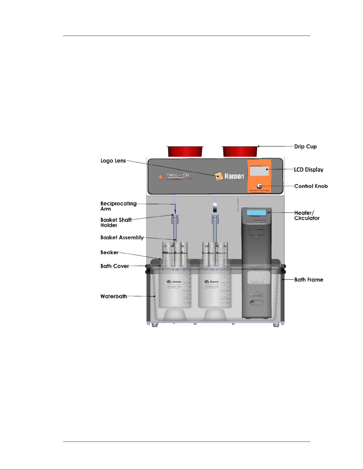
Phase One Disintegration Tester Overview
The Phase One Disintegration Tester is a two-basket system
designed to facilitate testing of tablet disintegration in
conformance with USP Chapters <701> and <2040> and other
harmonized international standards. The unit consists of a
waterbath, two beakers, two basket assemblies, one
heater/circulator, a set of two reciprocating arms driven by a
single electric motor, and other components as shown in the
illustration below.
The tester supports methods requiring two baskets running
simultaneously; the baskets are not independently controlled.
The standard tester configuration comes with two beakers and
two baskets pre-configured for 6-tube (USP Apparatus A) with
plastic disks. 3-tube baskets for Apparatus B are available
separately. The quick-connect basket assemblies snap onto the
basket shaft clips on the ends of the reciprocating arms that
provide the dipping action. The waterbath is easily removed
without tools for periodic cleaning.

A. Introduction
Phase One Disintegration Tester User Guide—40-108-001 Rev. A—14 November 2016 A-2
Tester Power Requirements
The internal power supply of the tester automatically switches
to accommodate either 120VAC/60Hz or 240VAC/50Hz. All
testers come with a detachable 120VAC cable with a 3-prong
plug to connect to the power source and a standard female
adapter to connect to the input module on the back of the tester.
Operating the tester on 240VAC requires an appropriate cable
(or adapter) suitable for connecting safely to the power source
and to the back of the tester.
Heater/Circulator
Heating and circulation of bath water is provided by a stand-
alone PolyScience Heater Circulator (H/C) unit featuring a built-
in over-temperature shut-off circuit. The H/C is self-contained
with an easy-to-read LCD display and a touchpad for setting the
temperature.
Heater Power Requirements
Heater/circulator power is dedicated to either 120VAC/60Hz (10
amps) or 240VAC/50Hz (6 amps), depending on which version
was purchased. The H/C has its own power cord configured for
the power supply specified at the time of the order. If the power
source outlet is configured differently than the plug on the H/C
cable as supplied, an appropriate adapter will be required. Note:
the outlet plug for the 240VAC version is IEC Type E.
WARNING! The maximum possible temperature able to be set
for the heater is 98 °C (factory-set limit). However, to avoid
distortion of the waterbath, bath lid, and baskets, and to protect
the tester warranty, the heater should never be allowed to run
higher than 55 °C.
Do not set heater
above 55 °C
A. Introduction
Phase One Disintegration Tester User Guide—40-108-001 Rev. A—14 November 2016 A-3
User Interface
The user interface of the Phase One Disintegration Tester
consists of an LCD display and a rotary control knob that allows
the user to select and activate each of the tester’s settings. All
operations are controlled with this knob.
Drip Cups
The low-profile plastic drip cups included with the unit are
designed to be placed under wet baskets for drip containment,
for example when baskets are being removed from the basket
shaft holders. They will also fit on top of the beakers and can be
used to plug the holes in the waterbath lid to reduce
evaporation.
Tester Operation Overview
Once the tester has been unpacked, installed and qualified,
routine operation consists of four steps: tester initialization; test
setup; running the disintegration test; and cleanup. The tester
has the ability to run a timed test or a continuous free run test.
A quick-start overview of the operational procedure is as
follows:
1. Power up tester and heater and initialize the tester.
2. Fill waterbath with DI water to the level indicated on the
label on the front of the bath.
3. Set heater/circulator to desired target temperature. (Do
not exceed 55 °C.)
4. Fill beakers with media to appropriate level.
5. Place tablets in baskets (along with plastic disks if
necessary).

A. Introduction
Phase One Disintegration Tester User Guide—40-108-001 Rev. A—14 November 2016 A-4
6. Install baskets on arms by snapping into basket shaft
holder.
7. Highlight the desired test mode—timed or free run.
8. If a timed test, set the time limit.
9. Start the test and monitor at appropriate points.
10. End the test and perform cleanup.
The above steps are described in greater detail in the Operation
section of this user guide.
Recommendations for Using This Manual
Hanson Research recommends the following steps for making
best use of this user guide:
1. Review the Introduction section for an overview of the
instrument.
2. Carefully review and follow all safety instructions.
3. Unpack, inspect, and install the tester according to
instructions in the Installation section.
4. Conduct an initial test of the system using the
procedures outlined in the Operation section.
5. Review the cleaning, maintenance, and troubleshooting
sections to become familiar with keeping the tester in
good working condition.
6. Immediately contact Hanson Technical Support with any
questions on how to properly operate and maintain the
Phase One Disintegration Tester.

B. Regulatory and Safety
Phase One Disintegration Tester User Guide—40-108-001 Rev. A—14 November 2016 B-1
Regulatory Compliance
Hanson Research hereby certifies that this product, including
hardware and firmware, was designed, evaluated, validated,
inspected, and tested to approved specified quality
requirements of Hanson Research Corp. in conformance with
current USP, EP, JP, and other international standards (India &
Korea).
Canadian Emissions Notice
This digital apparatus does not exceed the Class A limits for
radio noise emissions from digital apparatus set forth in the
Radio Interference Regulations of the Canadian Department of
Communications.
Le présent appareil numérique n’émet pas de bruits
radioélectriques dépassant les limites applicables aux appareils
numériques de la classe A prescrites dans les réglements sur
le brouillage radioélectrique édictés par le Ministére des
Communications du Canada.
General Safety Considerations
This equipment contains moving parts, which have the
potential to pinch or jam.
The installation category (overvoltage category) for this
instrument is Level II. The Level II category pertains to
equipment that receives its electrical power from a local
source such as an electrical wall outlet.
This instrument must be connected to a grounded
electrical outlet.
Never work on the electrical components in the system
while there is power to the unit. DISCONNECT POWER
BEFORE SERVICING THE INSTRUMENT.
Review all safety and environmental precautions pertaining
to any chemicals that are to be used in conjunction with
this equipment.

B. Regulatory and Safety
Phase One Disintegration Tester User Guide—40-108-001 Rev. A—14 November 2016 B-2
CSA Safety Considerations
• For indoor use only
• Maximum altitude 2,000 meters
• Environmental operating temperature 5 °C to 40 °C
• Operating relative humidity 80% for temperatures up to 31
°C, decreasing linearly to 50% relative humidity at 40 °C
• Mains supply ratings 100-240 V~, 50-60 Hz, 15 A
• Mains supply voltage fluctuations not to exceed ±10% of the
nominal voltage
• Installation Category II (overvoltage categories)
• Pollution Degree 2
• Please note potential pinch hazards described below.
• Additional hazards may exist if the equipment is not
operated according to the instructions in the user guide.
B. Regulatory and Safety
Phase One Disintegration Tester User Guide—40-108-001 Rev. A—14 November 2016 B-3
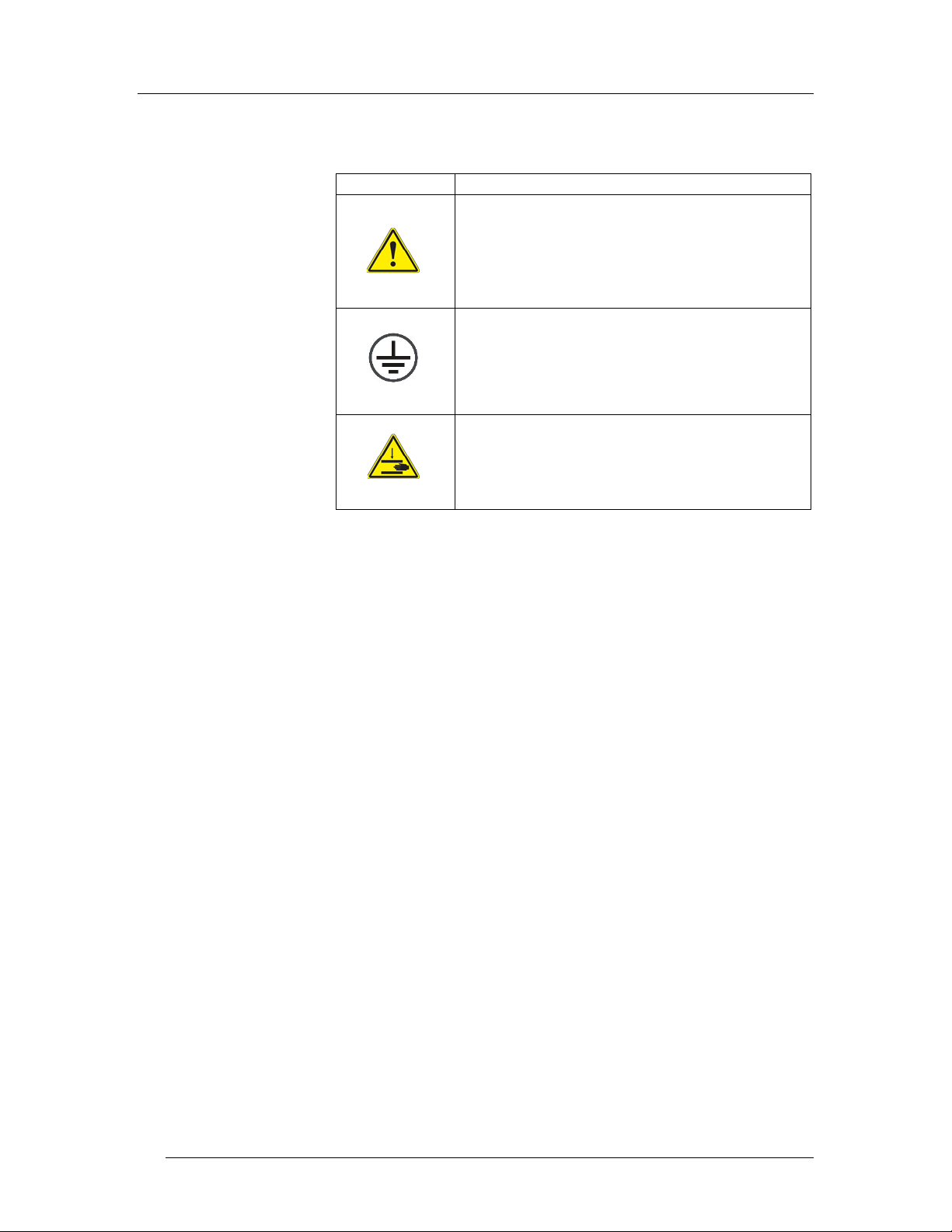
The following safety symbols are used throughout this manual.
Symbol Definition
General warning of potential damage or
danger from a variety of sources
Electrical grounding connection.
Pinch hazard; keep hands and fingers clear.

B. Regulatory and Safety
Phase One Disintegration Tester User Guide—40-108-001 Rev. A—14 November 2016 B-4
Warning Label Placements
A warning label is placed on the rear cover below the top middle
screw. This symbol indicates instrument maintenance must be
performed only by authorized service personnel. Injury can
occur if untrained personnel are servicing the tester with the
rear cover removed.
An electrical grounding symbol is placed on the inside floor of
the tester casing.
A warning label placed on the front of the heater/circulator alerts
the operator to the fact that the PolyScience manual must be
studied before operating the heater.
B. Regulatory and Safety
Phase One Disintegration Tester User Guide—40-108-001 Rev. A—14 November 2016 B-5
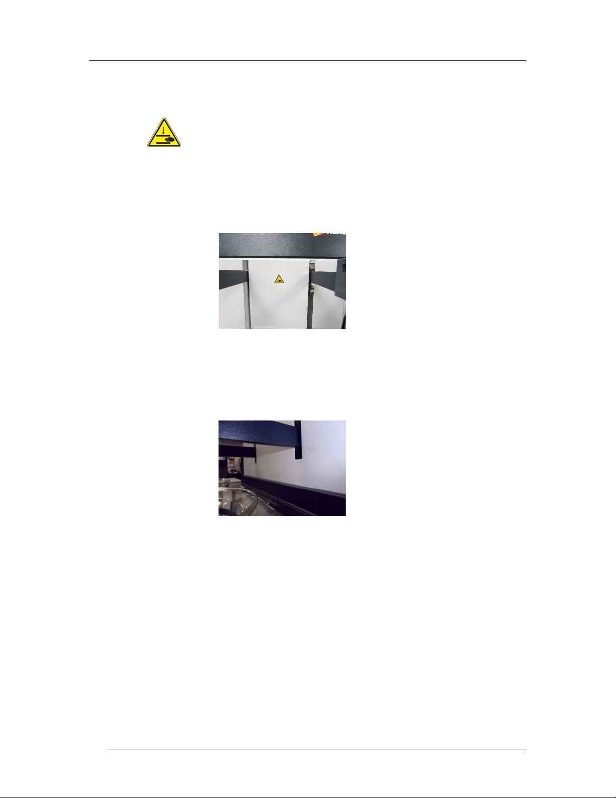
Pinch Hazards
There is a potential pinch point between the top of the basket
arms and the top edge of the slots through which the basket
arms extend when the arms travel to their uppermost position.
Although there is a clearance of about 15 mm (0.6 inches)
between the top of the arm and edge of the slot, and although
the arms cannot move further because the drive mechanism
prevents it, the operator should nevertheless keep clear of the
arms while they are moving.
A similar potential pinch point exists between the bottom edge
of the arms and the bottom edge of the slots when the arms are
fully lowered. The risk of injury is low since the arms are driven
downward only by gravity. Nevertheless, the operator should
remain clear of the arms while they are moving.

B. Regulatory and Safety
Phase One Disintegration Tester User Guide—40-108-001 Rev. A—14 November 2016 B-6
To authorized service personnel
When the back cover is removed, and power is supplied to the
drive motor, multiple components will rotate and slide when the
tester is commanded to run. These components are a potential
pinch hazard. Keeps hands free of this area when power is on.

C. Installation
Phase One Disintegration Tester User Guide—40-108-001 Rev. A—14 November 2016 C-1
Tester Installation
Review all safety instructions before proceeding with installation
of the Phase One Disintegration Tester.
The installation process consists of three steps:
1. Selecting an appropriate location, which includes
confirming environmental and space requirements.
2. Reviewing and conforming to electrical requirements.
3. Unpacking and installing the tester into the confirmed
location.
Proceed by following the instructions below.
Environmental Requirements
The installation location should be clean and free of factors that
may affect the integrity of disintegration testing results, such as
excessive vibration and significant variations in temperature.
Space Requirements
Please refer to Specifications section for space requirements
based on the physical dimensions of the tester.
The bench should be level and flat. It must be capable of
supporting the full weight (including water) of the tester.
Electrical Requirements
Each tester requires two grounded outlets within 1 meter (3 feet)
of the system—one for the disintegration tester, and one for the
heater/circulator. See power requirements in previous section.
Power cords must meet the following specifications: IEC 320-
C13 connector; SJT 18AWG, 3C, 60 °C, 300 V.
Unpacking and Inspection
Note: Moving, lifting, and carrying the Hanson Phase One
Disintegration Tester requires two people working together to
prevent damage to the instrument. Lift the instrument by the
bottom plate while supporting the back of the tester to prevent
it from tipping. The tester weighs 65 lbs. (29.5 kg).
Review all safety
instructions before
proceeding!

C. Installation
Phase One Disintegration Tester User Guide—40-108-001 Rev. A—14 November 2016 C-2
Unpack the Tester
While unpacking the tester, first make note of any damage to
the shipping container. If the container is damaged, contact the
shipper immediately.
1. Remove straps from shipping container.
2. Slide box up and away from enclosed components.
3. Remove any accessory boxes.
4. Carefully remove tester from shipping container.
5. Remove blue tape securing arms and remove plastic
wrap covering the bath lid.
6. Remove the bath lid.
7. Clean waterbath of packing material or other debris.
8. Place tester in final location on bench.
Assemble the Tester
1. Place heater into bath compartment (do not secure).
2. Install bath lid on top of bath while centering the heater
in the slot in the bath lid.
3. Clamp heater into place using knob on back of heater.
4. Use the cable clamps provided with the tester to route
the heater power cable, if desired.
5. Note: beakers and baskets cannot be installed until the
tester is initialized (Section D – Operation).
Electrical Connections
1. Ensure power switch on left back side of tester is in the
Off (O) position.
2. Ensure power switch back of heater unit is in the Off
(O) position.
3. Insert power cable into back of tester; plug outlet end
into power source.
4. Plug heater power cord into power source outlet.

D. Operation
Phase One Disintegration Tester User Guide—40-108-001 Rev. A—14 November 2016 D-1
Operation
Please review and follow all safety and installation instructions
before operating the Phase One Disintegration Tester. Before
turning on power to the unit, fill the bath with deionized water,
or better, to the line indicated on the front of the bath (without
beakers in place).
Power on the Tester
The power switch for the tester is located on the back side of
the unit. The switch is oriented for horizontal activation (toggle
to the left—-ON; toggle to the right—OFF (as viewed from the
front of the unit).
From the front of the tester reach around to the lower left back
corner to toggle the switch to the ON position. Except for
servicing, troubleshooting, operator preference, or protocol,
there is no need to turn the unit off after this.
The basket arms will not move when the tester is first powered
on. The LCD interface will display the Hanson name and logo
for a few seconds, along with the firmware version number as
shown below.
Fill bath before
turning on heater.

D. Operation
Phase One Disintegration Tester User Guide—40-108-001 Rev. A—14 November 2016 D-2
Initializing the Tester
With the unit powered on, the orange logo lens will begin
flashing, indicating an operator action is required. The
INITIALIZE screen will appear, instructing the operator to push
the control knob, with a caution that the arms will begin moving.
When the control knob is pressed, the arms will begin seeking
the HOME position, also called the LIFT position, in which the
baskets are raised completely out of the beakers.
When the initialization process is complete, the orange logo
lens will stop flashing and the main menu screen shown below
will appear on the display.

D. Operation
Phase One Disintegration Tester User Guide—40-108-001 Rev. A—14 November 2016 D-3
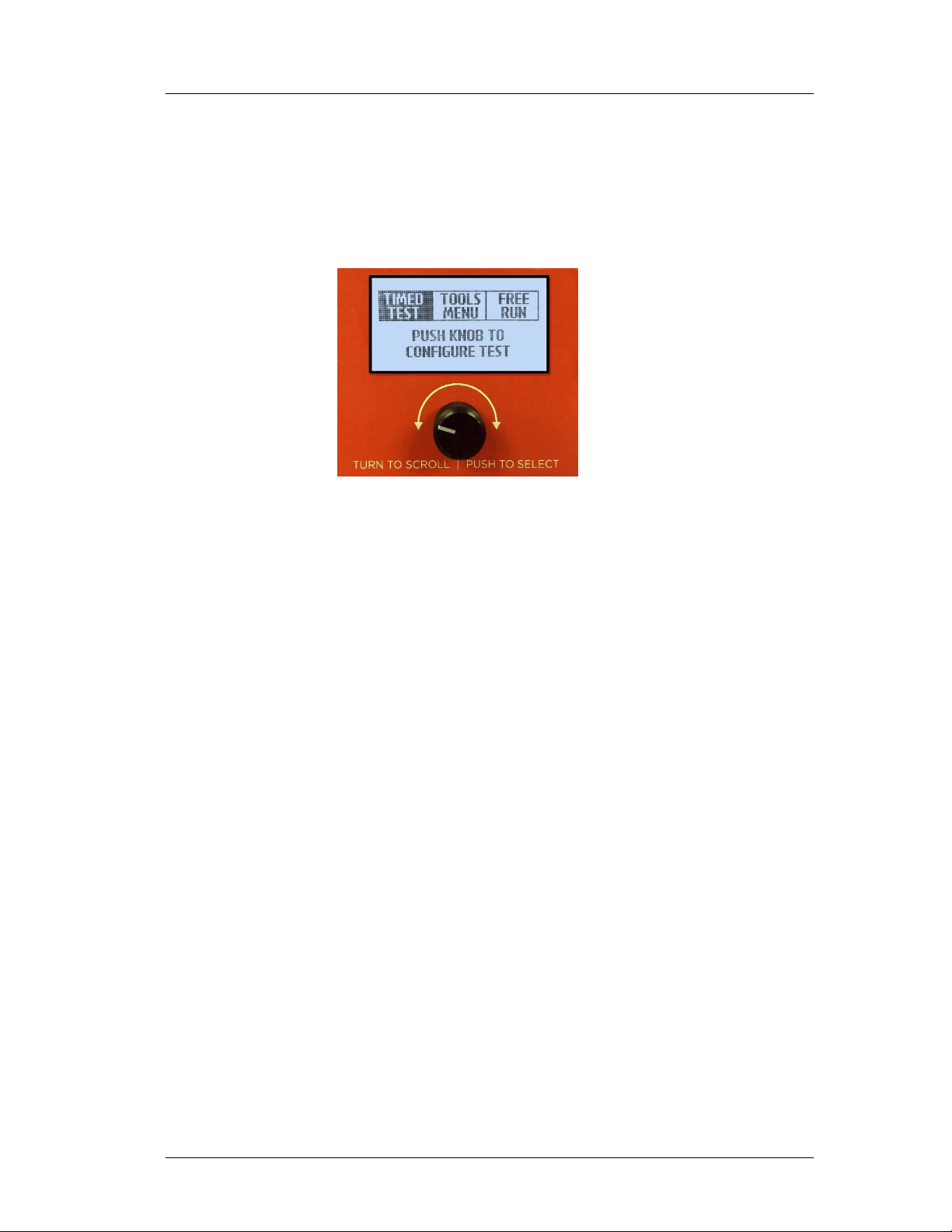
Screen Navigation Using the Control Knob
Rotating the control knob at this screen will highlight the three
most frequently used options of the instrument—TIMED TEST,
TOOLS MENU, and FREE RUN.
As each option is highlighted on the screen, a description of that
function is shown at the bottom of the display. Pushing the
control knob activates the highlighted option.
As each new screen is displayed, turning the control knob left
and right will highlight the options available on that screen. For
example, the green, yellow, and blue circles shown below
illustrate how an operator can reach various functions on other
screens by pushing the control knob at each circled option.
This manual suits for next models
2
Table of contents
Other Hanson Laboratory Equipment manuals


