manuals.online logo
Brands
  1. Home
  2. •
  3. Brands
  4. •
  5. HANYOUNG NUX
  6. •
  7. Measuring Instrument
  8. •
  9. HANYOUNG NUX HDM3 User manual

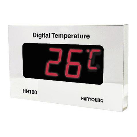
HANYOUNG NUX HDM3 User manual

MG0103E070216
HEAD OFFICE
1381-3, Juan-Dong, Nam-Gu Incheon, Korea
TEL:(82-32)876-4697 FAX:(82-32)876-4696
MAIN PRODUCTS
- DIGITAL : Temperature Controller, Counter, Timer,Speedmeter,
Tachometer, Panel Meter, Recorder
- SENSOR : Proximity Switch/Photo Electric Sensor,
Rotary Encoder, Optical Fiber Sensor,
Pressure Sensor
- ANALOG : Timer, Temperature Controller
Digital Gas Indicator
HDM3
We appreciate you for purchasing HanYoung NUX Co.,Ltd
product. Before using the product you have purchased,
check to make sure that it is exactly what you ordered.
Then, please use it following the instructions below.
INSTRUCTION MANUAL
Before you use, read safety precautions carefully, and use this product
properly. The precautions described in this manual contain important
contents related with safety; therefore, please follow the instructions
accordingly. The precautions are composed of DANGER, WARNING and
CAUTION.
There is a danger of occurring electric shock in the input/output terminals
so please never let your body or conductive substance is touched.
1.If there is a concern about a serious accident caused by a malfunction
or abnormality of this product, please install an external protection
circuit and devise a scheme for preventing an accident.
2.This product does not contain an electric switch or fuse, so the user
needs to install a separate electric switch or fuse externally.
(Fuse rating: 250V 0.5A)
3.There is voltage output of 24V built in this indicator.
4.Do not use load of more than 700mA.
5.To prevent defection or malfunction of this product, apply a proper
power voltage in accordance with the rating.
6.When altering the usage input range (SH, SL), ensure this is altered
prior to anything else. When the SH, SL are altered, it impacts the
other data and may generate unwanted results.
7.To prevent electric shock or malfunction of product, do not supply the
power until the wiring is completed.
8.Since this product is not designed with explosion-protective structure,
do not use it any place with flammable or explosive gas.
9.Do not decompose, modify, revise or repair this product. This may be a
cause of malfunction, electric shock or fire.
10.Reassemble this product while the power is OFF. Otherwise, it may be
a cause of malfunction or electric shock.
11.If you use the product with methods other than specified by the
manufacturer, there may be bodily injuries or property damages.
12.There is a possibility of occurring electric shock so please use this
product after installing it onto a panel while it is operating.
1.The contents of this manual may be changed without prior notification.
2.Make sure that there is no damage or abnormality of the product
during the delivery.
3.Use this product within the range of the operating ambient
temperature, 0 ~ 50 (When it is closely installed Max 40 ) and
ambient humidity, 20 ~ 90 % RH (No condensation).
4. Do not use this product at any place with occurring corrosive
(especially noxious gas or ammonia) or flammable gas.
5. Do not use this product at any place with direct vibration or impact.
6. Do not use this product at any place with liquid, oil, medical
substances, dust, salt or iron contents. (Use at Pollution level 1 or 2)
7. Do not polish this product with substances such as alcohol or benzene.
(Use neutral detergent.)
8. Do not use this product at any place with a large inductive difficulty or
occurring static electricity or magnetic noise.
9. Do not use this product at any place with possible thermal
accumulation due to direct sunlight or heat radiation.
10.Install this product at place under 2,000m in altitude.
11.When the product gets wet, the inspection is essential because there is
danger of an electric leakage or fire.
12.To avoid an effect of inductive noise to input signal cables, use the
product after separating the input signal cables from power, output and
load cables.
13.Separate an input signal cable from an output signal cable. If
separating is not possible, please use the input signal cable after
shielding it.
14.If there is excessive noise from the power supply, using insulating
transformer and noise filter is recommended. The noise filter must be
attached to a panel which is already connected to a ground and the
wire between the filter output side and power supply terminal must be
short as possible.
15.If twisting the power cables closely together then it is effective against
noise.
16.Turn the power OFF when replacing a sensor.
17.The front of this machine is waterproof, in accordance to IP65,
however, as for the meter and panel, the attached gasket must be
used in order to ensure waterproof property. Therefore, please be sure
to insert the gasket in between the panel and the meter unfolded.
18.Do not connect anything to the unused terminals.
19.After checking the polarity of terminal, connect wires at the correct
position.
20.When this product is connected onto a panel, use a circuit breaker or
switch approved with IEC947-1 or IEC947-3.
21.For the continuous and safe use of this product, the periodical
maintenance is recommended.
22.Some parts of this product have limited life span, and others are
changed by their usage.
23.The warranty period for this product including parts is one year if this
product is properly used.
Safety information
WARNING
DANGER
CAUTION
Ratings and Capacity
Dimension and Panel Cutout
Code
Rated Voltage
Input
Output
Insulation resistance
Dielectric strength
Operating condition
Storage condition
100-240 V a.c, 50/60 Hz( 10 %)
Input points : 3 channels
Accuracy : 0.1 % of FS
Sampling cycle : 125 ms 3 channels = 375 ms
Input correction : -100 ~ 100 % of FS
Input Filter : 0 ~ 100 s
Output points : 6 points
Contact capacity : 5 A 240 V a.c, 5 A 30 V d.c
Resolution : 125 ms
Hysteresis : 0 ~ 10 % of FS
500 V d.c 20
2300 V a.c 50/60 Hz for 1 minute
Temperature : -5 ~ 50
Humidity : 20 ~ 90 % RH(No dew condensation)
Temperature : -25 ~ 70
Humidity : 5 ~ 95 % RH(No dew condensation)
bar
bar
bar
122.0
70.0
[Unit : mm]
Contents
Set maximum scale
Set minimum scale
Decimal Point Placement
Input Filter
Input Revision
Channel Skip
Set HIGH ZONE
Set LOW ZONE
Hysteresis
LOCK
SH
SL
DP
FL
BSn
CHn
AnL
AnLL
HYSn
LOC
Description
Indicated Value of Maximum
Input (20mA)
Indicated Value of
Minimum Input (4mA)
Decimal Point Placement
Input Filter
Input Revision
Select Channel Skip
Set HIGH ZONE
Set LOW ZONE
Hysteresis Relay
Prohibit Data Change
Range
Default
SL ~9999
0 ~ SH
0 ~ 2
OFF(0) ~ 100
EUS(-100~100%)
OFF, ON
AnLL ~ SH
SL ~ AnL
EUS (0 ~ 10 %)
OFF, ON
Indicator
Contents
HDM3 SYSTEM Error
AD Conversion Error
Status of all channels
“skipped”
Sensor Error
Over the limit for Input (More
than 20mA is inputted)
Over the limit for Input
(Less than 4mA is inputted)
EEPROM Error
SYSE
ADC
CHDS
BOUT
OVR
MOVR
EEP
ZONE Relay Control
All relays for channels
are “OFF”
All relays for channels
are “OFF”
All relays for channels
are “OFF”
Relays for selected
channel is “OFF”
HIGH ZONE Relay for
selected channel is “ON”
LOW ZONE Relay is “ON”
for the selected channel
Normal Operation
All relays for channels
are “OFF”
All relays for channels
are “OFF”
All relays for channels
are “OFF”
Relays for selected
channel is “OFF”
HIGH ZONE LED “ON”
for selected channel
LOW ZONE LED is “ON”
for the selected channel
Normal Operation
When the parameter name and the
parameter value are displayed on the
indicator panel in alternately, press
or ,
Then only the parameter value is displayed, and at this time,
by using the keys, to change the value, after which
the SET key is pressed.
Parameter Name Parameter Value
Parameter Value
The changed parameter values are registered,
and the parameter name and the
parameter value are displayed in alternate.
n = 1~3 (Channel Number)
When altering the usage input range (SH, SL), ensure this is altered prior to
anything else. When the SH, SL are altered, it impacts the other data and
may enerate unwanted results.
Channel Skip
The selected channel is skipped when “CHn” is OFF.
Then the skipped channel LED and the Relay operations all become
“OFF”status.
Automatic Scan Mode
At the operating display, pressing “SET” key for more than 1 second turns to
the “Auto Scan” Mode. While in the “Auto Scan” mode, it scans the channels
that are “CHn = ON” and displays for approximately 2 seconds
each.However, if a channel has a certain problem, the “Auto Scan” is
stopped and the problem status is displayed with the channel locked.
Manual Scan Mode
At the operating display, pressing the “SET” key turns to the “Manual Scan”
Mode.While in the Manual Scan Mode, every time the “SET” is pressed
once, the channels that has “CHn = ON” is scanned and displayed.
n = 1~3 (Channel Number)
Cantion : Do not connect anything to NC
n = 1~3 (Channel Number)
Parameter Name Changed 
Parameter Value
P1
4 20 mA
100 - 240 V AC
50 / 60 Hz FG
P2
4 20 mA P3
4 20 mA
P2
L.LOW
ZONE
P2
LOW
ZONE
COM
P1
L.LOW
ZONE
P1
LOW
ZONE
COM
NC
NC
COM
P3
L.LOW
ZONE
P3
LOW
ZONE
12345678910
11 12 13 14 15 16 17 18 19 20
Pn.AnL+Pn.HYSn
Pn.AnL
Pn.AnLL+Pn.HYSn
Pn.AnLL
LOW ZONE Relay
L.LOW ZONE Relay
RED LED
YELLOW LED
GREEN LED
ON ON
ON ON
ON ON
ON
ON
ON
: HIGH ZONE Lamp of each of P1, 2, 3. (Green)
: MIDDLE ZONE Lamp of each of P1,2,3. (Yellow)
: LOW ZONE Lamp of each of P1,2,3. (Red
: Channel Indicating Lamp of each of P1,2,3 (Green)
: PV Indicator Panel
: DOT Indicator
SET: SET Key
: Direction Setting Shifting Key
: Setting Level Reduction Key
: Setting Level Increasing Key
POWER ON
TEST Screen Operating
Screen
HDM3
MODEL
display
SET+UP
SET SET
SET SET
SET SET
SET SET
SET SET
SET SET
SET SET
SET SET
SET SET
SET SET
SET 3 sec SET 3 sec
SET+SFT
Automatic return 
after TEST
OPERATION SETUP
A1L SH
A1LL SL
HYS1 DP
A2L FL
A2LL BS1
HYS2 BS2
A3L BS3
A3LL CH1
HYS3 CH2
LOC CH3
Automatic Scan Mode :
Press “SET”key for 1 second to enter
to the “Auto Scan”. While in the
Auto Scan”mode, it scans the channels
for approximately 2 seconds each.
Manual Scan Mode :
Press the "SET" key turns to the
"Manual Scan" mode. Every time the "SET"
is pressed once, the channel is scanned
and displayed.
※When an error has occurred during
“Auto Scan”, the scan is stopped
at the channel.
7 Segments
individual LED test PV display
Condition display
Wiring Diagram
The name of each part
Parameter Transition Diagram
To change the parameter
Parameter
Relationship between the ZONE, the relay and the LED.
Channel Scan

Other HANYOUNG NUX Measuring Instrument manuals

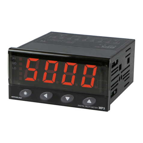
HANYOUNG NUX MP3-4 H Series User manual

HANYOUNG NUX

HANYOUNG NUX MP3-4 H Series User manual

HANYOUNG NUX BS Series User manual

HANYOUNG NUX

HANYOUNG NUX BS Series User manual

HANYOUNG NUX TP3 User manual

HANYOUNG NUX

HANYOUNG NUX TP3 User manual

HANYOUNG NUX TP3 User manual

HANYOUNG NUX

HANYOUNG NUX TP3 User manual

HANYOUNG NUX RP3 User manual

HANYOUNG NUX

HANYOUNG NUX RP3 User manual

HANYOUNG NUX MP3 User manual

HANYOUNG NUX

HANYOUNG NUX MP3 User manual

HANYOUNG NUX GR200 Series User manual

HANYOUNG NUX

HANYOUNG NUX GR200 Series User manual

HANYOUNG NUX BA1 User manual

HANYOUNG NUX

HANYOUNG NUX BA1 User manual

HANYOUNG NUX ED6 User manual

HANYOUNG NUX

HANYOUNG NUX ED6 User manual

HANYOUNG NUX MP3 User manual

HANYOUNG NUX

HANYOUNG NUX MP3 User manual

HANYOUNG NUX TP3 User manual

HANYOUNG NUX

HANYOUNG NUX TP3 User manual

HANYOUNG NUX HL Series User manual

HANYOUNG NUX

HANYOUNG NUX HL Series User manual

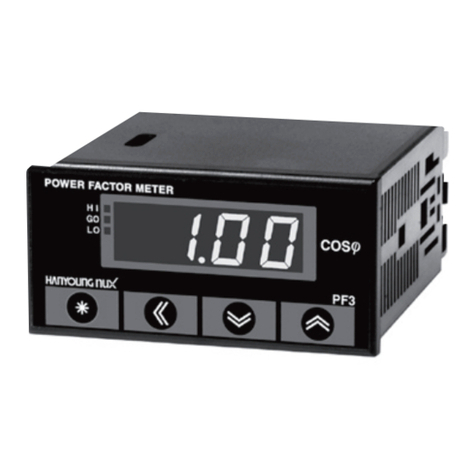
HANYOUNG NUX PF3 User manual

HANYOUNG NUX

HANYOUNG NUX PF3 User manual

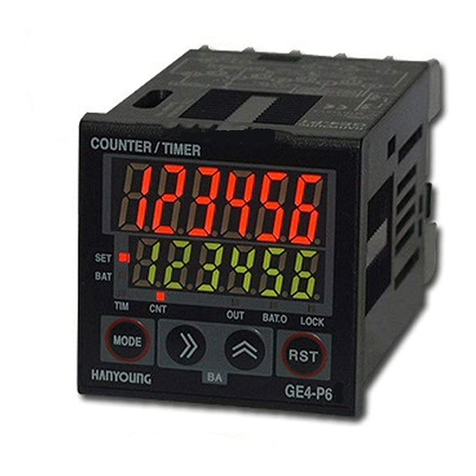
HANYOUNG NUX GE Series User manual

HANYOUNG NUX

HANYOUNG NUX GE Series User manual

HANYOUNG NUX BK3 User manual

HANYOUNG NUX

HANYOUNG NUX BK3 User manual

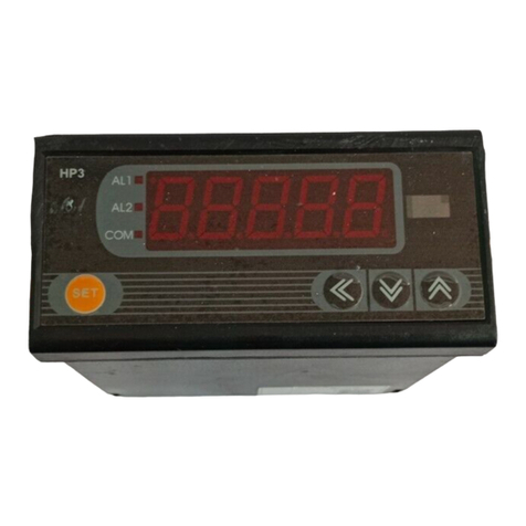
HANYOUNG NUX HP3 User manual

HANYOUNG NUX

HANYOUNG NUX HP3 User manual

HANYOUNG NUX BA 1 Series User manual

HANYOUNG NUX

HANYOUNG NUX BA 1 Series User manual

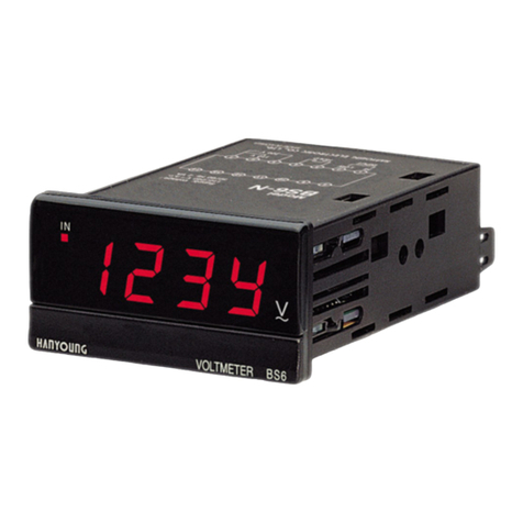
HANYOUNG NUX BS6 User manual

HANYOUNG NUX

HANYOUNG NUX BS6 User manual

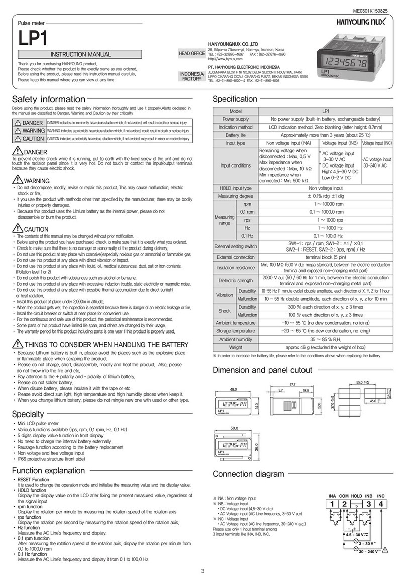
HANYOUNG NUX LP1 User manual

HANYOUNG NUX

HANYOUNG NUX LP1 User manual

HANYOUNG NUX HN100 Series User manual

HANYOUNG NUX

HANYOUNG NUX HN100 Series User manual

HANYOUNG NUX HE Series User manual

HANYOUNG NUX

HANYOUNG NUX HE Series User manual

Popular Measuring Instrument manuals by other brands

Innova 3160g owner's manual

Innova

Innova 3160g owner's manual

audioscan RM500SL user guide

audioscan

audioscan RM500SL user guide

Tegam 720A quick start guide

Tegam

Tegam 720A quick start guide

Ditel JUNIOR JR-D user manual

Ditel

Ditel JUNIOR JR-D user manual

Michell Instruments XZR250 quick start guide

Michell Instruments

Michell Instruments XZR250 quick start guide

Katronic KATflow 200 operating instructions

Katronic

Katronic KATflow 200 operating instructions

Hanna Instruments HI 60503 instruction manual

Hanna Instruments

Hanna Instruments HI 60503 instruction manual

HBM FS42 user manual

HBM

HBM FS42 user manual

Keysight Technologies B2900 Series user guide

Keysight Technologies

Keysight Technologies B2900 Series user guide

RADECO H-810BL Operation and maintenance manual

RADECO

RADECO H-810BL Operation and maintenance manual

Anton Paar SmartRef Instruction Manual and Safety Information

Anton Paar

Anton Paar SmartRef Instruction Manual and Safety Information

Keysight N1911A installation guide

Keysight

Keysight N1911A installation guide

GREISINGER GIR1002 FR Connecting and Operating Manual

GREISINGER

GREISINGER GIR1002 FR Connecting and Operating Manual

MSA Mini ID R-1234yf Operation manual

MSA

MSA Mini ID R-1234yf Operation manual

ProMinent DULCOTEST PAA 1-mA-200 ppm operating instructions

ProMinent

ProMinent DULCOTEST PAA 1-mA-200 ppm operating instructions

LD U300 IEM Series user manual

LD

LD U300 IEM Series user manual

Industrial Fiber Optics ML 800 Series Operator's manual

Industrial Fiber Optics

Industrial Fiber Optics ML 800 Series Operator's manual

SENSIRION Nubo Sphere user manual

SENSIRION

SENSIRION Nubo Sphere user manual

manuals.online logo
manuals.online logoBrands
  • About & Mission
  • Contact us
  • Privacy Policy
  • Terms and Conditions

Copyright 2025 Manuals.Online. All Rights Reserved.