Harbor Freight Tools ZR8S OBD2 User manual

OBD2
Code Reader
Professional Diagnostics
for the Master Technician
ZR8S

Table of Contents
i
ABOUT THE SCAN TOOL
SAFETY FIRST! ....................................................................... 1
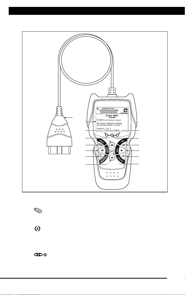
CONTROLS AND INDICATORS .............................................. 2
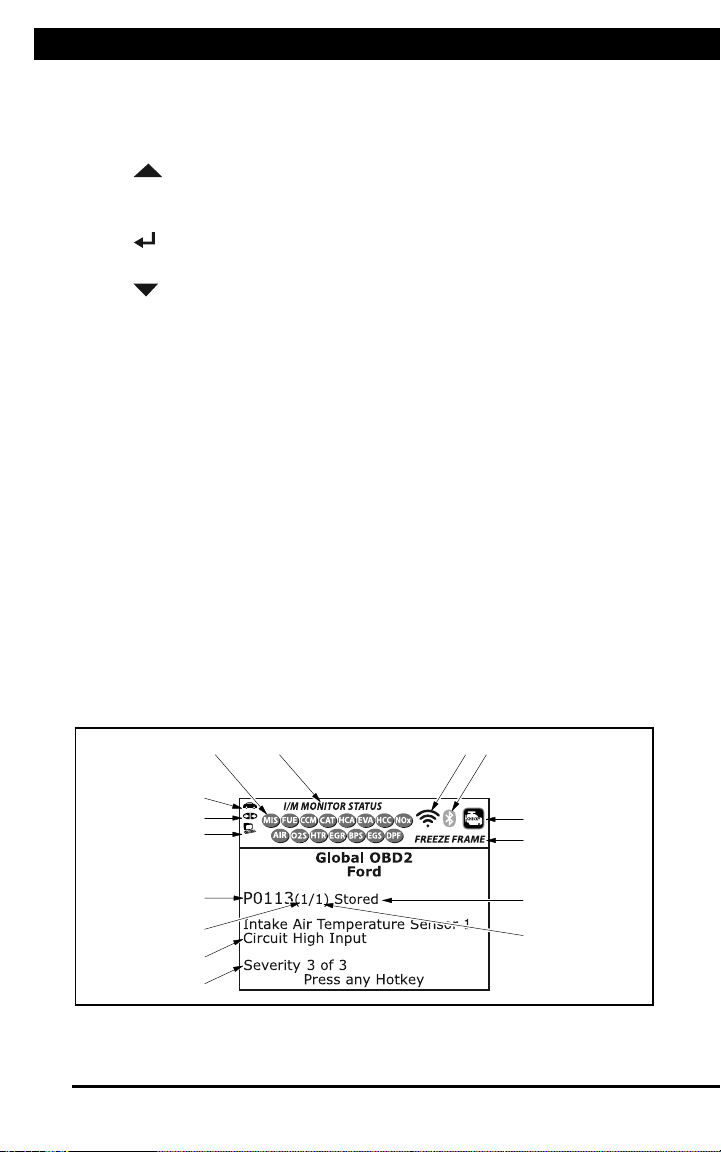
DISPLAY FUNCTIONS ............................................................ 3
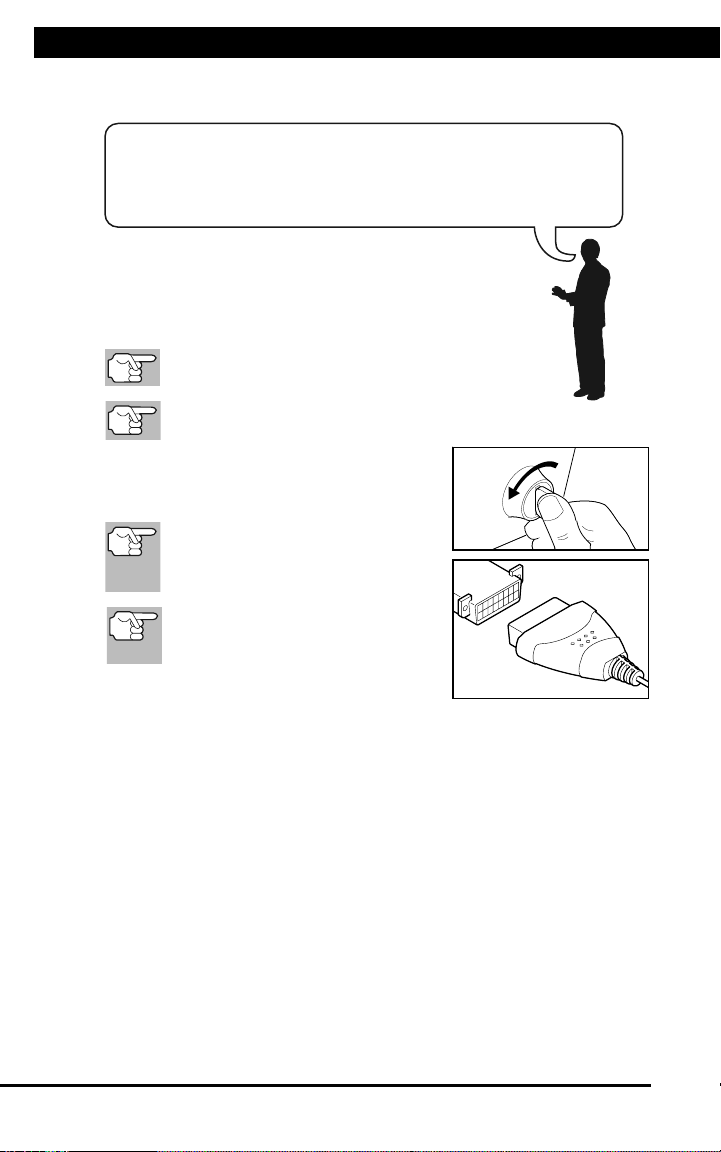
INITIAL ADJUSTMENTS .......................................................... 5
USING THE SCAN TOOL
CODE RETRIEVAL PROCEDURE .......................................... 6
ERASING DIAGNOSTIC TROUBLE CODES (DTCs).............. 10
ABOUT REPAIRSOLUTIONS 2® ............................................ 11
CONNECTING TO BLUETOOTH / WIFI ................................. 12
ADDITIONAL FUNCTIONS
VIEWING VEHICLE INFORMATION ....................................... 14
EVAP TEST .............................................................................. 16
VIEWING MONITOR ICON DESCRIPTIONS ......................... 16
VIEWING LED DEFINITIONS .................................................. 17
SELECTING THE DISPLAY LANGUAGE ............................... 17
ADJUSTING DISPLAY BRIGHTNESS .................................... 17
ENABLING/DISABLING THE AUDIBLE TONE ....................... 18
ENABLING/DISABLING NAVIGATIONAL FOOTERS ............. 18
VIEWING THE HOTKEY LEGEND .......................................... 18
SETTING THE UNIT OF MEASUREMENT ............................. 19
WARRANTY AND SERVICING
LIMITED ONE YEAR WARRANTY........................................... 21
SERVICE PROCEDURES ....................................................... 21
SAFETY PRECAUTIONS
IMPORTANT SAFETY INFORMATION ..............................
SCAN TOOL CONTROLS
CONTROLS AND INDICATORS .........................................
DISPLAY FUNCTIONS .......................................................
INITIAL ADJUSTMENTS ....................................................
USING THE SCAN TOOL
CODE RETRIEVAL PROCEDURE .....................................
ERASING DIAGNOSTIC TROUBLE CODES (DTCs) ........
ABOUT REPAIRSOLUTIONS 2® .......................................
CONNECTING BLUETOOTH / WIFI ..................................
ADDITIONAL FUNCTIONS
VIEWING VEHICLE INFORMATION ..................................
EVAP TEST ........................................................................
VIEWING MONITOR ICON DESCRIPTIONS ....................
VIEWING LED DEFINITIONS ............................................
SELECTING DISPLAY LANGUAGE ..................................
ADJUSTING DISPLAY BRIGHTNESS ...............................
ENABLING/DISABLING AUDIBLE TONE ..........................
ENABLING/DISABLING NAVIGATIONAL FOOTERS ........
VIEWING HOTKEY LEGEND .............................................
SETTING UNIT OF MEASUREMENT ................................
WARRANTY AND SERVICING
LIMITED 90 DAY WARRANTY ...........................................
SERVICE PROCEDURES ..................................................
1
2
3
5
6
10
11
12
14
16
16
17
17
17
18
18
18
19
21
21
TABLE OF CONTENTS
SAFETY PRECAUTIONS
IMPORTANT SAFETY INFORMATION .....................................
SCAN TOOL CONTROLS
CONTROLS AND INDICATORS ................................................
DISPLAY FUNCTIONS ..............................................................
INITIAL ADJUSTMENTS ............................................................
USING THE SCAN TOOL
CODE RETRIEVAL PROCEDURE ............................................
THEY SYSTEM MENU ..............................................................
VIEWING OEM ENHANCED DTCs (Except for Ford/Mazda) ...
VIEWING OEM ENHANCED DTCs (Ford/Mazda Only) ............
VIEWING ARS DTCs .................................................................
VIEWING SRS DTCs .................................................................
NETWORK TEST .......................................................................
ERASING DIAGNOSTIC TROUBLE CODES (DTCs) ...............
ABOUT REPAIRSOLUTIONS® .................................................
CONNECTING TO BLUETOOTH / WIFI ...................................
LIVE DATA MODE
VIEWING LIVE DATA .................................................................
CUSTOMIZING LIVE DATA (PIDs) ............................................
RECORDING (CAPTURING) LIVE DATA ..................................
LIVE DATA PLAYBACK ..............................................................
ADDITIONAL TESTS
SYSTEM TEST MENU ...............................................................
RESETTING THE OIL MAINTENANCE LIGHT .........................
BATTERY RESET ......................................................................
PERFORMING A SERVICE CHECK .........................................
BATTERY/ALTERNATOR TEST ................................................
VIEWING DRIVE CYCLE PROCEDURES ................................
USING DLC LOCATOR .............................................................
VIEWING VEHICLE INFORMATION .........................................
VIEWING THE FIRMWARE VERSION ......................................
THE TOOL LIBRARY .................................................................
ADJUSTMENTS AND SETTINGS .............................................
WARRANTY AND SERVICING
LIMITED 90 DAY WARRANTY ...................................................
SERVICE PROCEDURES .........................................................
1
2
3
5
6
11
11
12
14
15
16
19
20
21
23
24
25
28
30
33
34
36
36
39
40
41
42
43
45
49
49

For technical questions, please call 1-888-866-5797 1
TITLEIMPORTANT SAFETY INFORMATION
About the Scan Tool
SAFETY FIRST
1
):?N!?@@!C?O:9P!Q?8=>=RC!?=N!?@@!>=C98B;9>7=CM!
$?>@B8:!97!O7@@7Q!9<:!Q?8=>=RC!?=N!>=C98B;9>7=C!S?P!8:CB@9!>=!:@:;98>;!
C<7;TD!O>8:!?=NU78!C:8>7BC!>=VB8PM!
"?W:!?@@!Q?8=>=RC!?=N!>=C98B;9>7=C!O78!OB9B8:!8:O:8:=;:M!
1. %B?EHCWKX! H! Y?ZWAL?! WKFDDE=! 0()! O"11! -%4! ")! #")4',*.! ,KXWK?
?@ZH[=C!ADKCHWK=!AHE\DK!]DKD@WF?.!'ZW=!W=!H!BDW=DK!MD[!AHKKDC!=??
DE!=]?LL.!),8,&!DB?EHC?!Y?ZWAL?!WK=WF?!H!ZD]?!DE!XHEHX?V!,8,)!"+
FDDE=!HKF!^WKFD^=!HE?!DB?K.!!%KLM![=?!%4'*"2,!HKF!_HE!H^HM!_ED]
^WKFD^=V!FDDE=V!HKF!Y?KC=.
2. $?DBL?!^WCZ!BHA?]H`?E=!=ZD[LF!ADK=[LC!CZ?WE!BZM=WAWHK>=J!\?_DE?![=?.
,L?ACED]HXK?CWA! _W?LF=! WK! ALD=?! BED@W]WCM! CD! Z?HEC! BHA?]H`?E! AD[LF
AH[=?! BHA?]H`?E! WKC?E_?E?KA?! DE! BHA?]H`?E! _HWL[E?.! 0H[CWDK! W=
K?A?==HEM!^Z?K!K?HE!ADWLV!=BHE`!BL[X!AH\L?=V!DE!FW=CEW\[CDE!D_!E[KKWKX
?KXWK?.!,KXWK?!=ZD[LF!\?!D__!F[EWKX!FW=CEW\[CDE!HFa[=C]?KC.
3. O??B!ALDCZWKXV!ZHWEV!ZHKF=V!CDDL=V!C?=C!?b[WB]?KCV!?CA.!H^HM!_ED]!HLL
]DYWKX!DE!ZDC!?KXWK?!BHEC=.
4. $[C! CZ?! CEHK=]W==WDK! WK! $(&O! >_DE! H[CD]HCWA! CEHK=]W==WDKJ! DE
),4'&(1! >_DE! ]HK[HL! CEHK=]W==WDKJ! HKF! ]H`?! =[E?! CZ?! BHE`WKX
\EH`?!W=!?KXHX?F.
5. $[C!\LDA`=!WK!_EDKC!D_!HKF!\?ZWKF!CZ?!FEWY?!^Z??L=.
6. &?HF! Y?ZWAL?! =?EYWA?! ]HK[HL! \?_DE?! WK=B?ACWKXV! ]HWKCHWKWKXV! DE
E?BHWEWKX!H!Y?ZWAL?.
7. ;?HE!()*"cHBBEDY?F!=H_?CM!XDXXL?=.
8. )?Y?E!L?HY?!CZ?!Y?ZWAL?![KHCC?KF?F!^ZWL?!E[KKWKX!C?=C=.
9. O??B!H!_WE?!?@CWKX[W=Z?E!=[WCH\L?!_DE!XH=DLWK?GAZ?]WAHLG?L?ACEWAHL!_WE?=
K?HE\M.
10. 2DKdC!ADKK?AC!DE!FW=ADKK?AC!HKM!C?=C!?b[WB]?KC!^ZWL?!CZ?!WXKWCWDK!W=
DK!DE!CZ?!?KXWK?!W=!E[KKWKX.
11. 'ZW=!BEDF[AC!W=!KDC!H!CDM.!O??B!WC!D[C!D_!E?HAZ!D_!AZWLFE?K.
12. O??B!CZ?!*AHK!'DDL!FEMV!AL?HKV!_E??!_ED]!DWLV!^HC?E!DE!XE?H=?.!4=?!H
]WLF!F?C?EX?KC!DK!H!AL?HK!ALDCZ!CD!AL?HK!CZ?!D[C=WF?!D_!CZ?!*AHK!'DDLV
^Z?K!K?A?==HEM.
13. 'Z?! ^HEKWKX=V! BE?AH[CWDK=V! HKF! WK=CE[ACWDK=! FW=A[==?F! WK! CZW=
WK=CE[ACWDK!]HK[HL!AHKKDC!ADY?E!HLL!BD==W\L?!ADKFWCWDK=!HKF!=WC[HCWDK=
CZHC!]HM!DAA[E.!"C!][=C!\?![KF?E=CDDF!\M!CZ?!DB?EHCDE!CZHC!AD]]DK
=?K=?!HKF!AH[CWDK!HE?!_HACDE=!^ZWAZ!AHKKDC!\?!\[WLC!WKCD!CZW=!BEDF[ACV
\[C!][=C!\?!=[BBLW?F!\M!CZ?!DB?EHCDE.
!"#2%!&1%"%!,."&)+*&,-."M!
IMPORTANT SAFETY INFORMATION

For technical questions, please call 1-888-866-57972
CONTROLS AND INDICATORS
Scan Tool Controls
CONTROLS AND INDICATORS
2
CONTROLS AND INDICATORS
Figure 1. Controls and Indicators
See Figure 1 for the locations of items 1 through 14, below.
1. ERASE button - Erases Diagnostic Trouble Codes (DTCs),
and “Freeze Frame” data from your vehicle’s computer, and resets
Monitor status.
2. SYSTEM MENU button – When pressed, displays the System
Test Menu.
3. DTC/FF button - Displays the DTC View screen and/or scrolls the
LCD display to view DTCs and Freeze Frame data.
4. POWER/LINK button - When not connected to a vehicle,
turns the Scan Tool “On” and “Off” (press and hold for 3 seconds).
When connected to a vehicle, links the Scan Tool to the vehicle’s
PCM.
1
2
3
4
5
6
8
9
711
12
10
14
13

For technical questions, please call 1-888-866-5797 3
DISPLAY FUNCTIONS
Scan Tool Controls
DISPLAY FUNCTIONS
3
5. Mbutton – When pressed, displays the Main Menu.
6. LD button – When pressed while linked to a vehicle, places the
Scan Tool in Live Data mode.
7. UP button – When in MENU mode, scrolls UP through the
menu options. When LINKED to a vehicle, scrolls UP through the
current display screen to display any additional data.
8. ENTER button - When in MENU mode, confirms the selected
option or value.
9. DOWN button - When in MENU mode, scrolls DOWN through
the menu options. When LINKED to a vehicle, scrolls DOWN
through the current display screen to display any additional data.
10. GREEN LED - Indicates that all engine systems are running
normally (all Monitors on the vehicle are active and performing their
diagnostic testing, and no DTCs are present).
11. YELLOW LED - Indicates there is a possible problem. A “Pending”
DTC is present and/or some of the vehicle’s emission monitors have
not run their diagnostic testing.
12. RED LED - Indicates there is a problem in one or more of the
vehicle’s systems. The red LED is also used to show that DTC(s)
are present. DTCs are shown on the Scan Tool’s display. In this
case, the Malfunction Indicator (“Check Engine”) lamp on the
vehicle’s instrument panel will light steady on.
13. Display - Color LCD display shows menu and submenus, test
results, Scan Tool functions and Monitor status information. See
DISPLAY FUNCTIONS, following, for more details.
14. CABLE - Connects the Scan Tool to the vehicle’s Data Link
Connector (DLC).
DISPLAY FUNCTIONS
Figure 2. Display Functions
See Figure 2 for the locations of items 1 through 15, below.
4
3
2
5
7
6
1 14
10
11
12
8
9
13
15

For technical questions, please call 1-888-866-57974
DISPLAY FUNCTIONS
Scan Tool Controls
DISPLAY FUNCTIONS
4
1. I/M MONITOR STATUS field - Identifies the I/M Monitor status area.
2. Monitor icons - Indicate which Monitors are supported by the
vehicle under test, and whether or not the associated Monitor has
run its diagnostic testing (Monitor status). A solid green icon
indicates the associated Monitor has completed its diagnostic
testing. A flashing red icon indicates that the vehicle supports the
associated Monitor, but the Monitor has not yet run its diagnostic
testing.
3. Vehicle icon - When visible, indicates that the Scan Tool is
being powered through the vehicle’s DLC connector.
4. Link icon - When visible, indicates the Scan Tool is
communicating with the vehicle’s computer.
5. Computer icon - When visible, indicates the Scan Tool is linked
to a personal computer.
6. DTC Display Area - Displays the Diagnostic Trouble Code (DTC)
number. Each fault is assigned a code number that is specific to that
fault. The DTC number is color-coded as follows:
RED - Indicates the currently displayed DTC is a STORED or
PERMANENT DTC.
YELLOW - Indicates the currently displayed DTC is a PENDING
DTC.
GREEN - In cases where no codes are retrieved, a “No DTCs
are presently stored in the vehicle’s computer” message is
shown in green.
7. Code Number Sequence - The Scan Tool assigns a sequence
number to each DTC that is present in the computer’s memory,
starting with “1.” This number indicates which code is currently
displayed. Code number “1” is always the highest priority code, and
the one for which “Freeze Frame” data has been stored.
If “1” is a “Pending” code, there may or may not be “Freeze
Frame” data stored in memory.
8. Code Enumerator - Indicates the total number of codes retrieved
from the vehicle’s computer.
9. Test Data Display Area - Displays DTC definitions, Freeze Frame
data and other pertinent test information messages.
10. SYSTEM icon - Indicates the system with which the code is
associated:
MIL icon ABS icon SRS icon
11. FREEZE FRAME icon - Indicates that there is Freeze Frame data
from “Priority Code” (Code #1) stored in the vehicle’s computer
memory.
12. Code type - Indicates the type of code being displayed; Generic
Stored, Generic Pending, Generic permanent, etc.

For technical questions, please call 1-888-866-5797 5
INITIAL ADJUSTMENTS
Scan Tool Controls
INITIAL ADJUSTMENTS
5
13. Severity - Indicates the level of severity for the priority code (code
number “1”), as follows:
1 -Service should be scheduled and repairs made when
convenient. This DTC typically has no immediate threat to
essential system components in the short term.
2 -Repair immediately if drivability issues are present. Threat to
essential system components if not repaired as soon as possible.
3 -Stop and repair vehicle immediately to prevent interrelated
failures. Harmful and damaging to essential system components.
14. Bluetooth icon – Indicates communication status with a compat-
ible Innova mobile application (please visit www.innova.com/apps
for more information). A solid blue icon indicates an active Bluetooth
connection has been established. A solid grey icon indicates
Bluetooth is not connected.
15. Wi-Fi icon – Indicates Wi-Fi communication status. When ON,
indicates the scan tool is linked to a Wi-Fi network. When OFF,
indicates there is no Wi-Fi connection.
INITIAL ADJUSTMENTS
The first time the unit is connected to a vehicle, you must select the
desired display language (English, French or Spanish) and unit of
measurement (Standard or metric) as follows:
1. Select the desired display language, then press ENTER .
The Select Unit screen displays.
2. Select the desired unit of measurement, then press ENTER .
After the initial language and unit of measurement selections
are performed, these, as well as other settings, can be
changed as desired. Proceed to “ADJUSTMENTS AND
SETTINGS” on page 45 for further instructions.

For technical questions, please call 1-888-866-57976
CODE RETRIEVAL PROCEDURE
Using the Scan Tool
CODE RETRIEVAL PROCEDURE
6
Retrieving and using Diagnostic Trouble Codes (DTCs) for
troubleshooting vehicle operation is only one part of an
overall diagnostic strategy.
CODE RETRIEVAL PROCEDURE
Never replace a part based only on the DTC definition.
Each DTC has a set of testing procedures, instructions and
flow charts that must be followed to confirm the location of
the problem. Always refer to the vehicle's service manual
for detailed testing instructions.
Check your vehicle thoroughly before performing
any test.
ALWAYS observe safety precautions whenever working on a
vehicle.
1. Turn the ignition off.
2. Locate the vehicle's 16-pin Data Link
Connector (DLC).
Some DLCs have a plastic cover
that must be removed before
connecting the Scan Tool cable
connector.
If the Scan Tool is ON, turn it OFF
BEFORE connecting the Scan
Tool to the DLC.
3. Connect the Scan Tool to the vehicle’s
DLC. The cable connector is keyed and
will only fit one way.
If you have problems connecting the cable connector to the DLC,
rotate the connector 180°.
If you still have problems, check the DLC on the vehicle and on
the Scan Tool.
4. Turn the ignition on. DO NOT start the engine.
5. When the Scan Tool is properly connected to the vehicle’s DLC, the
unit automatically turns ON.
If the unit does not power on automatically, it may indicate there
is no power present at the vehicle’s DLC connector. Check the
fuse panel and replace any burned-out fuses.
If replacing the fuse(s) does not correct the problem, consult your
vehicle’s repair manual to identify the proper computer (PCM)
fuse/circuit, and perform any necessary repairs before proceeding.

For technical questions, please call 1-888-866-5797 7
CODE RETRIEVAL PROCEDURE
Using the Scan Tool
CODE RETRIEVAL PROCEDURE
6
Retrieving and using Diagnostic Trouble Codes (DTCs) for
troubleshooting vehicle operation is only one part of an
overall diagnostic strategy.
CODE RETRIEVAL PROCEDURE
Never replace a part based only on the DTC definition.
Each DTC has a set of testing procedures, instructions and
flow charts that must be followed to confirm the location of
the problem. Always refer to the vehicle's service manual
for detailed testing instructions.
Check your vehicle thoroughly before performing
any test.
ALWAYS observe safety precautions whenever working on a
vehicle.
1. Turn the ignition off.
2. Locate the vehicle's 16-pin Data Link
Connector (DLC).
Some DLCs have a plastic cover
that must be removed before
connecting the Scan Tool cable
connector.
If the Scan Tool is ON, turn it OFF
BEFORE connecting the Scan
Tool to the DLC.
3. Connect the Scan Tool to the vehicle’s
DLC. The cable connector is keyed and
will only fit one way.
If you have problems connecting the cable connector to the DLC,
rotate the connector 180°.
If you still have problems, check the DLC on the vehicle and on
the Scan Tool.
4. Turn the ignition on. DO NOT start the engine.
5. When the Scan Tool is properly connected to the vehicle’s DLC, the
unit automatically turns ON.
If the unit does not power on automatically, it may indicate there
is no power present at the vehicle’s DLC connector. Check the
fuse panel and replace any burned-out fuses.
If replacing the fuse(s) does not correct the problem, consult your
vehicle’s repair manual to identify the proper computer (PCM)
fuse/circuit, and perform any necessary repairs before proceeding.
Using the Scan Tool
CODE RETRIEVAL PROCEDURE
7
6. The Scan Tool automatically starts a check of the vehicle’s
computer to determine which type of communication protocol it is
using. When the Scan Tool identifies the computer’s communication
protocol, a communication link is established.
A PROTOCOL is a set of rules and procedures for regulating
data transmission between computers, and between testing
equipment and computers. As of this writing, five different types
of protocols (ISO 9141, Keyword 2000, J1850 PWM, J1850
VPW and CAN) are in use by vehicle manufacturers.
If the Scan Tool fails to link to the vehicle’s computer, a
“Communication Error” message shows.
- Ensure your vehicle is OBD2 compliant.
- Verify the connection at the DLC, and verify the ignition is ON.
- Turn the ignition OFF, wait 5 seconds, then back ON to reset
the computer.
- Press the LINK to continue.
If the Scan Tool cannot link to the vehicle’s computer after three
attempts, the message “Contact Technical Support” displays.
- Press SYSTEM MENU to return to the System Menu.
- Turn the ignition off, and
disconnect the Scan Tool.
- Contact Technical Support for
assistance.
7. If the Scan Tool can decode the Vehicle
Identification Number (VIN) for the
vehicle under test, the Confirm Vehicle
screen displays.
If the information shown is correct for the vehicle under test,
select Yes, then press ENTER . Proceed to step 10 .
If the information shown is not correct for the vehicle under test,
or if you wish to manually select the vehicle, select No, then
press ENTER . Proceed to step 8.
If the Scan Tool cannot decode the Vehicle Identification
Number (VIN) for the vehicle under test, the Select Vehicle
screen displays. Proceed to step 8.
8. When No is selected from the Vehicle
information screen, the Select Vehicle
screen displays. The Select Vehicle
screen lists the three most recently
tested vehicles.
To select a previously tested vehicle,
select the desired vehicle, then press
ENTER . Proceed to step 10 .

For technical questions, please call 1-888-866-57978
CODE RETRIEVAL PROCEDURE
Using the Scan Tool
CODE RETRIEVAL PROCEDURE
8
To select a new vehicle, select New
Vehicle, then press ENTER .
Proceed to step 9.
9. When New Vehicle is chosen from the
Select Vehicle screen, the Select Year
screen displays.
Select the desired vehicle model
year, then press ENTER to
continue.
- The Select Make screen dis-
plays.
Select the desired vehicle make,
then press ENTER to continue.
- The Select Model screen dis-
plays.
Select the desired vehicle model,
then press ENTER to continue.
- The Select Engine screen
displays.
Select the desired vehicle engine
size, then press ENTER to
continue.
- The Select Transmission screen
displays.
Select the desired transmission type,
then press ENTER to continue.
The Vehicle Information screen
displays.
If the information shown is correct
for the vehicle under test, select
Yes, then press ENTER .
Proceed to step 10.
If the information shown is not correct for the vehicle under test,
or if you wish to reselect the vehicle, select No, then press
ENTER to return to the Select Year screen.
10. After approximately 10~60 seconds, the Scan Tool will retrieve and
display any Diagnostic Trouble Codes, Monitor Status and Freeze
Frame Data retrieved from the vehicle’s computer memory.
The Scan Tool will display a code only if codes are present. If no
codes are present, the message “No Powertrain DTCs or Freeze
Frame Data presently stored in the vehicle’s computer” displays.
The Scan Tool is capable of retrieving and storing up to 32
codes in memory, for immediate or later viewing.

For technical questions, please call 1-888-866-5797 9
CODE RETRIEVAL PROCEDURE
Using the Scan Tool
CODE RETRIEVAL PROCEDURE
9
11. Refer to DISPLAY FUNCTIONS on page 3 for a description of
display elements.
In the case of long code definitions,
a small arrow is shown in the
upper/lower right-hand corner of the
Scan Tool display area to indicate
the presence of additional
information.
If a definition for the currently
displayed code is not available,
an advisory message shows.
12. Read and interpret Diagnostic Trouble Codes/system condition
using the display and the green, yellow and red LEDs.
The green, yellow and red LEDs are used (with the display) as
visual aids to make it easier to determine engine system
conditions.
Green LED – Indicates that all
engine systems are “OK” and
operating normally. All monitors
supported by the vehicle have run
and performed their diagnostic
testing, and no trouble codes are
present. All Monitor icons will be
solid.
Yellow LED – Indicates one of the
following conditions:
A. A PENDING CODE IS PRESENT –
If the yellow LED is illuminated, it
may indicate a Pending code is
present. Check the display for
confirmation. A Pending code is
confirmed by the presence of a
numeric code and the word
PENDING.
B. MONITOR NOT RUN STATUS – If
the display shows a zero (indicating
there are no DTC’s present in the
vehicle’s computer memory), but
the yellow LED is illuminated, it may
be an indication that some of the
Monitors supported by the vehicle
have not yet run and completed
their diagnostic testing. Check the
display for confirmation. All Monitor
icons that are blinking have not yet
run and completed their diagnostic
testing; all Monitor icons that are
solid have run and completed their
diagnostic testing.

For technical questions, please call 1-888-866-579710
CODE RETRIEVAL PROCEDURE
Using the Scan Tool
CODE RETRIEVAL PROCEDURE
10
Red LED – Indicates there is a
problem with one or more of the
vehicle’s systems. The red LED is
also used to indicate that DTC(s)
are present. In this case, the
Malfunction Indicator (Check Engine)
lamp on the vehicle’s instrument
panel will be illuminated.
DTC’s that start with “P0”, “P2” and
some “P3” are considered Generic
(Universal). All Generic DTC definitions are the same on all OBD2
equipped vehicles. The Scan Tool automatically displays the code
definitions (if available) for Generic DTC’s.
DTC’s that start with “P1” and some “P3” are Manufacturer specific
codes and their code definitions vary with each vehicle
manufacturer.
13. If more than one DTC was retrieved, and to view Freeze Frame
Data, press and release DTC/FF, as necessary.
Each time DTC/FF is pressed and released, the Scan Tool will
scroll and display the next DTC in sequence until all DTCs in its
memory have displayed.
Freeze Frame Data (if available) will display after DTC #1.
In OBD2 systems, when an emis-
sions-related engine malfunction oc-
curs that causes a DTC to set, a re-
cord or snapshot of engine conditions
at the time that the malfunction
occurred is also saved in the vehicle’s
computer memory. The record saved
is called Freeze Frame data. Saved
engine conditions include, but are not
limited to: engine speed, open or closed loop operation, fuel system
commands, coolant temperature, calculated load value, fuel
pressure, vehicle speed, air flow rate, and intake manifold pressure.
If more than one malfunction is present that causes more than
one DTC to be set, only the code with the highest priority will
contain Freeze Frame data. The code designated “01” on the
Scan Tool display is referred to as the PRIORITY code, and
Freeze Frame data always refers to this code. The priority
code is also the one that has commanded the MIL on.
14. When the last retrieved DTC has been displayed and DTC/FF is
pressed, the Scan Tool returns to the “Priority” Code.
15. Determine engine system(s) condition by viewing the Scan Tool’s
display for any retrieved Diagnostic Trouble Codes, code definitions
and Freeze Frame data, interpreting the green, yellow and red LEDs.
If DTC’s were retrieved and you are going to perform the repairs
yourself, proceed by consulting the Vehicle’s Service Repair
Manual for testing instructions, testing procedures, and flow
charts related to retrieved code(s).
Using the Scan Tool
THE SYSTEM MENU - VIEWING OEM ENHANCED DTCs (except Ford/Mazda)
11
THE SYSTEM MENU
The System Menu provides the ability to retrieve “enhanced” DTCs, Anti-
Lock Brake System (ABS) and Supplemental Restraint System (SRS)
DTCs for most BMW, Chrysler/Jeep, Ford/Mazda, GM/Isuzu, Honda/Acura,
Hyundai, Mercedes Benz, Nissan, Toyota/Lexus, Volkswagen and Volvo
vehicles. The types of enhanced data available depends on the vehicle
make. You can also return to the Global OBD2 mode.
Depending on the vehicle under test, some features and functions
may not be available.
To access the System Menu, press
SYSTEM MENU . Select the desired
option, then press ENTER to view
the selected information.
To view ABS DTCs: Select ABS from the
System Menu. Refer to VIEWING ABS
DTCs on page 14 to view ABS DTCs for
your vehicle.
To view SRS DTCs: Select SRS from the System Menu. Refer to
VIEWING SRS DTCs on page 15 to view SRS DTCs for your vehicle.
To view OEM enhanced DTCs: Select OEM Enhanced from the
System Menu. Refer to VIEWING OEM ENHANCED DTCs on page 11
to view OEM enhanced DTCs for your vehicle.
To perform a Network Test: Select All Module Scan or Select
Modules, as desired. Refer to NETWORK TEST on page 16 to view
DTCs for other modules.
VIEWING OEM ENHANCED DTCs (except Ford/Mazda)
When (make)OEM Enhanced is chosen from the System Menu, the
Scan Tool retrieves OEM enhanced DTCs from the vehicle’s computer.
1. A “One moment please” message displays while the Scan Tool
retrieves the selected DTCs.
If the Scan Tool fails to link to the vehicle’s computer, a
“Communication Error” message shows.
- Ensure your vehicle is OBD2 compliant.
- Verify the connection at the DLC, and verify the ignition is ON.
- Turn the ignition OFF, wait 5 seconds, then back ON to reset
the computer.
- Press LINK to continue.
If the Scan Tool cannot link to the vehicle’s computer after three
attempts, the message “Contact Technical Support” displays.
- Press SYSTEM MENU to return to the System Menu.
- Turn the ignition off, and disconnect the Scan Tool.
- Contact Technical Support for assistance.

For technical questions, please call 1-888-866-5797 11
SYSTEM MENU - ENHANCED DTCs
Using the Scan Tool
CODE RETRIEVAL PROCEDURE
10
Red LED – Indicates there is a
problem with one or more of the
vehicle’s systems. The red LED is
also used to indicate that DTC(s)
are present. In this case, the
Malfunction Indicator (Check Engine)
lamp on the vehicle’s instrument
panel will be illuminated.
DTC’s that start with “P0”, “P2” and
some “P3” are considered Generic
(Universal). All Generic DTC definitions are the same on all OBD2
equipped vehicles. The Scan Tool automatically displays the code
definitions (if available) for Generic DTC’s.
DTC’s that start with “P1” and some “P3” are Manufacturer specific
codes and their code definitions vary with each vehicle
manufacturer.
13. If more than one DTC was retrieved, and to view Freeze Frame
Data, press and release DTC/FF, as necessary.
Each time DTC/FF is pressed and released, the Scan Tool will
scroll and display the next DTC in sequence until all DTCs in its
memory have displayed.
Freeze Frame Data (if available) will display after DTC #1.
In OBD2 systems, when an emis-
sions-related engine malfunction oc-
curs that causes a DTC to set, a re-
cord or snapshot of engine conditions
at the time that the malfunction
occurred is also saved in the vehicle’s
computer memory. The record saved
is called Freeze Frame data. Saved
engine conditions include, but are not
limited to: engine speed, open or closed loop operation, fuel system
commands, coolant temperature, calculated load value, fuel
pressure, vehicle speed, air flow rate, and intake manifold pressure.
If more than one malfunction is present that causes more than
one DTC to be set, only the code with the highest priority will
contain Freeze Frame data. The code designated “01” on the
Scan Tool display is referred to as the PRIORITY code, and
Freeze Frame data always refers to this code. The priority
code is also the one that has commanded the MIL on.
14. When the last retrieved DTC has been displayed and DTC/FF is
pressed, the Scan Tool returns to the “Priority” Code.
15. Determine engine system(s) condition by viewing the Scan Tool’s
display for any retrieved Diagnostic Trouble Codes, code definitions
and Freeze Frame data, interpreting the green, yellow and red LEDs.
If DTC’s were retrieved and you are going to perform the repairs
yourself, proceed by consulting the Vehicle’s Service Repair
Manual for testing instructions, testing procedures, and flow
charts related to retrieved code(s).
Using the Scan Tool
THE SYSTEM MENU - VIEWING OEM ENHANCED DTCs (except Ford/Mazda)
11
THE SYSTEM MENU
The System Menu provides the ability to retrieve “enhanced” DTCs, Anti-
Lock Brake System (ABS) and Supplemental Restraint System (SRS)
DTCs for most BMW, Chrysler/Jeep, Ford/Mazda, GM/Isuzu, Honda/Acura,
Hyundai, Mercedes Benz, Nissan, Toyota/Lexus, Volkswagen and Volvo
vehicles. The types of enhanced data available depends on the vehicle
make. You can also return to the Global OBD2 mode.
Depending on the vehicle under test, some features and functions
may not be available.
To access the System Menu, press
SYSTEM MENU . Select the desired
option, then press ENTER to view
the selected information.
To view ABS DTCs: Select ABS from the
System Menu. Refer to VIEWING ABS
DTCs on page 14 to view ABS DTCs for
your vehicle.
To view SRS DTCs: Select SRS from the System Menu. Refer to
VIEWING SRS DTCs on page 15 to view SRS DTCs for your vehicle.
To view OEM enhanced DTCs: Select OEM Enhanced from the
System Menu. Refer to VIEWING OEM ENHANCED DTCs on page 11
to view OEM enhanced DTCs for your vehicle.
To perform a Network Test: Select All Module Scan or Select
Modules, as desired. Refer to NETWORK TEST on page 16 to view
DTCs for other modules.
VIEWING OEM ENHANCED DTCs (except Ford/Mazda)
When (make)OEM Enhanced is chosen from the System Menu, the
Scan Tool retrieves OEM enhanced DTCs from the vehicle’s computer.
1. A “One moment please” message displays while the Scan Tool
retrieves the selected DTCs.
If the Scan Tool fails to link to the vehicle’s computer, a
“Communication Error” message shows.
- Ensure your vehicle is OBD2 compliant.
- Verify the connection at the DLC, and verify the ignition is ON.
- Turn the ignition OFF, wait 5 seconds, then back ON to reset
the computer.
- Press LINK to continue.
If the Scan Tool cannot link to the vehicle’s computer after three
attempts, the message “Contact Technical Support” displays.
- Press SYSTEM MENU to return to the System Menu.
- Turn the ignition off, and disconnect the Scan Tool.
- Contact Technical Support for assistance.

For technical questions, please call 1-888-866-579712
ENHANCED DTCs (FORD / MAZDA ONLY)
Using the Scan Tool
VIEWING OEM ENHANCED DTCs (Ford/Mazda only)
12
2. Refer to DISPLAY FUNCTIONS on page 2 for a description of LCD
display elements.
If the definition for the currently
displayed code is not available,
an advisory message shows.
I/M MONITOR STATUS icons
are not displayed when
viewing enhanced DTCs.
In the case of long code
definitions, a small arrow is
shown in the upper/lower
right-hand corner of the code display area to indicate the
presence of additional information.
If no codes are present, the message “No OEM Enhanced DTC’s
are presently stored in the vehicle’s computer” shows. Press
SYSTEM MENU to return to the System Menu.
3. If more than one code was retrieved press DTC/FF, as necessary,
to display additional codes one at a time.
Whenever the Scroll function is used to view additional codes,
the Scan Tool’s communication link with the vehicle’s computer
disconnects. To re-establish communication, press LINK
again.
4. When the last retrieved DTC has been displayed and DTC/FF is
pressed, the Scan Tool returns to the “Priority” Code.
To exit the enhanced mode, press SYSTEM MENU to return
to the System Menu. Select Global OBD, then press ENTER
to return to the Global OBD2 mode.
VIEWING OEM ENHANCED DTCs (Ford/Mazda only)
Mazda Enhanced DTCs are available for Mazda-branded
Ford vehicles only.
When Ford OEM Enhanced is chosen from
the System Menu, the Ford Enhanced
menu displays. You may view OEM DTCs
for either the “Continuous Memory Test”,
“KOEO (Key On Engine Off) Test” or
“KOER (Key On Engine Running) Test.”
1. Select the desired option, then press
ENTER .
If KOER is selected, an advisory message shows.
- Start and warm the engine to normal operating temperature,
then press ENTER . Proceed to step 3.
2. If KOEO or Continuous Memory is selected, an “instructional”
message shows.

For technical questions, please call 1-888-866-5797 13
ENHANCED DTCs (FORD / MAZDA ONLY)
Using the Scan Tool
VIEWING OEM ENHANCED DTCs (Ford/Mazda only)
13
Turn the ignition OFF, then back ON. Press ENTER .
Proceed to step 3.
3. A “One moment please” message displays while the test is in progress.
If the Scan Tool fails to link to the vehicle’s computer, a
“Communication Error” message shows.
- Ensure your vehicle is OBD2 compliant.
- Verify the connection at the DLC, and verify the ignition is ON.
- Turn the ignition OFF, wait 5 seconds, then back ON to reset
the computer.
- Press LINK to continue.
If the Scan Tool cannot link to the vehicle’s computer after three
attempts, the message “Contact Technical Support” displays.
- Press SYSTEM MENU to return to the System Menu.
- Turn the ignition off, and disconnect the Scan Tool.
- Contact Technical Support for assistance.
If the KOER Test was selected, and the vehicle’s engine is not
running, an advisory message shows.
- Start the engine and press ENTER to try again, or, press
SYSTEM MENU to return to the System Menu.
If the KOEO Test was selected, and the vehicle’s engine is
running, an advisory message shows.
- Turn the ignition OFF then back ON and press ENTER to
try again, or, press the SYSTEM MENU button to return to
the System Menu.
4. If the KOER test was selected, an “instructional” message shows.
Turn the steering wheel to the left, then release.
Press and release the brake pedal.
Cycle the overdrive switch (if equipped).
A “One moment please” message displays while the test is in
progress.
5. Refer to DISPLAY FUNCTIONS on page 2 for a description of LCD
display elements.
I/M MONITOR STATUS icons
are not displayed when
viewing enhanced DTCs.
In the case of long code
definitions, a small arrow is
shown in the upper/lower
right-hand corner of the code
display area to indicate the
presence of additional
information.

For technical questions, please call 1-888-866-579714
ABS DTCs
Using the Scan Tool
VIEWING ABS DTCs
14
If no codes are present, a “System
Pass” message is displays. Press
any Hotkey.
6. If more than one code was retrieved
press DTC/FF to display additional
codes one at a time.
7. When the last retrieved DTC has been
displayed and DTC/FF is pressed, the
Scan Tool returns to the “Priority” Code.
To view additional enhanced DTCs, repeat steps 1through 5,
above.
To exit the enhanced mode, press SYSTEM MENU to return
to the System Menu. Select Global OBD, then press ENTER
to return to the Global OBD2 mode.
VIEWING ABS DTCs
Refer to the manufacturer’s website for vehicle makes covered.
Reading ABS DTCs
1. When ABS is chosen from the System Menu, a "One moment
please" message displays while the Scan Tool retrieves the selected
DTCs.
If ABS functionality is not supported, an advisory message
shows. Press SYSTEM MENU to return to the System Menu.
If the Scan Tool fails to link to the vehicle’s computer, a
"Communication Error" message shows.
- Ensure your vehicle is OBD2 compliant.
- Verify the connection at the DLC, and verify the ignition is ON.
- Turn the ignition OFF, wait 5 seconds, then back ON to reset
the computer.
- Press LINK to continue.
If the Scan Tool cannot link to the vehicle’s computer after three
attempts, the message “Contact Technical Support” displays.
- Press SYSTEM MENU to return to the System Menu.
- Turn the ignition off, and disconnect the Scan Tool.
- Contact Technical Support for assistance.
2. Refer to DISPLAY FUNCTIONS on page 2 for a description of LCD
display elements.

For technical questions, please call 1-888-866-5797 15
SRS DTCs
Using the Scan Tool
VIEWING ABS DTCs
14
If no codes are present, a “System
Pass” message is displays. Press
any Hotkey.
6. If more than one code was retrieved
press DTC/FF to display additional
codes one at a time.
7. When the last retrieved DTC has been
displayed and DTC/FF is pressed, the
Scan Tool returns to the “Priority” Code.
To view additional enhanced DTCs, repeat steps 1through 5,
above.
To exit the enhanced mode, press SYSTEM MENU to return
to the System Menu. Select Global OBD, then press ENTER
to return to the Global OBD2 mode.
VIEWING ABS DTCs
Refer to the manufacturer’s website for vehicle makes covered.
Reading ABS DTCs
1. When ABS is chosen from the System Menu, a "One moment
please" message displays while the Scan Tool retrieves the selected
DTCs.
If ABS functionality is not supported, an advisory message
shows. Press SYSTEM MENU to return to the System Menu.
If the Scan Tool fails to link to the vehicle’s computer, a
"Communication Error" message shows.
- Ensure your vehicle is OBD2 compliant.
- Verify the connection at the DLC, and verify the ignition is ON.
- Turn the ignition OFF, wait 5 seconds, then back ON to reset
the computer.
- Press LINK to continue.
If the Scan Tool cannot link to the vehicle’s computer after three
attempts, the message “Contact Technical Support” displays.
- Press SYSTEM MENU to return to the System Menu.
- Turn the ignition off, and disconnect the Scan Tool.
- Contact Technical Support for assistance.
2. Refer to DISPLAY FUNCTIONS on page 2 for a description of LCD
display elements.
Using the Scan Tool
VIEWING SRS DTCs
15
If the definition for the currently
displayed code is not available,
an advisory message shows.
I/M MONITOR STATUS icons
are not displayed when
viewing ABS DTCs.
In the case of long code definitions, a small arrow is shown
in the upper/lower right-hand corner of the code display
area to indicate the presence of additional information.
If no codes are present, the message "No ABS DTC’s are
presently stored in the vehicle’s computer" shows. Press the
SYSTEM MENU button to return to the System Menu.
3. If more than one code was retrieved press DTC/FF to display
additional codes one at a time.
Whenever the Scroll function is used to view additional codes,
the Scan Tool’s communication link with the vehicle’s computer
disconnects. To re-establish communication, press LINK
again.
4. When the last retrieved DTC has been displayed and DTC/FF is
pressed, the Scan Tool returns to the “Priority” Code.
To exit the enhanced mode, press SYSTEM MENU to return
to the System Menu. Select Global OBD, then press ENTER
to return to the Global OBD2 mode.
VIEWING SRS DTCs
Refer to the manufacturer’s website for vehicle makes covered.
Reading SRS DTCs
1. When SRS DTCs is chosen from the System Menu, a "One moment
please" message displays while the Scan Tool retrieves the selected
DTCs.
If SRS functionality is not supported, an advisory message
shows. Press SYSTEM MENU to return to the System Menu.
If the Scan Tool fails to link to the vehicle’s computer, a
"Communication Error" message shows.
- Ensure your vehicle is OBD2 compliant.
- Verify the connection at the DLC, and verify the ignition is ON.
- Turn the ignition OFF, wait 5 seconds, then back ON to reset
the computer.
- Press LINK to continue.

For technical questions, please call 1-888-866-579716
NETWORK TEST
Using the Scan Tool
NETWORK TEST
16
If the Scan Tool cannot link to the vehicle’s computer after three
attempts, the message “Contact Technical Support” displays.
- Press SYSTEM MENU to return to the System Menu.
- Turn the ignition off, and disconnect the Scan Tool.
- Contact Technical Support for assistance.
2. Refer to DISPLAY FUNCTIONS on page 2 for a description of LCD
display elements.
If the definition for the currently
displayed code is not available,
an advisory message shows.
I/M MONITOR STATUS icons
are not displayed when viewing
SRS DTCs.
In the case of long code
definitions, a small arrow is
shown in the upper/lower right-hand corner of the code
display area to indicate the presence of additional
information.
If no codes are present, the message "No SRS DTC’s are
presently stored in the vehicle’s computer" shows. Press the
SYSTEM MENU button to return to the System Menu.
3. If more than one code was retrieved press DTC/FF to display
additional codes one at a time.
Whenever the Scroll function is used to view additional codes, the
Scan Tool’s communication link with the vehicle’s computer discon-
nects. To re-establish communication, press LINK again.
4. When the last retrieved DTC has been displayed and DTC/FF is
pressed, the Scan Tool returns to the “Priority” code.
To exit the enhanced mode, press SYSTEM MENU to return
to the System Menu. Select Global OBD, then press ENTER
to return to the Global OBD2 mode.
NETWORK TEST
The Network Test lets you perform a scan of all vehicle modules, or of a
single selected module, to retrieve DTCs associated with the module(s).
To scan all modules:
1. Select All Module Scan from the System Menu, then press ENTER
.
A “One moment please” message
displays while the Scan Tool scans
all available modules.
When the scan is complete, the
Available Systems screen displays.
The screen shows the number of

For technical questions, please call 1-888-866-5797 17
NETWORK TEST
Using the Scan Tool
NETWORK TEST
17
DTCs recorded for each available module.
2. Select the module for which you wish to view DTCs, then press
ENTER . A “One moment please” message displays while the
requested DTCs are retrieved.
If the Scan Tool fails to link to the selected module, a
“Communication Error” message shows.
- Ensure your vehicle is OBD2 compliant.
- Verify the connection at the DLC, and verify the ignition is ON.
- Turn the ignition OFF, wait 5 seconds, then back ON to reset
the computer.
- Press POWER/LINK to continue, or, press System
Menu to return to the System Menu.
If the selected module does not support the “Read DTC” function,
an advisory message displays. Press System Menu to
return to the System Menu, or, press Mto access the Main
Menu.
3. Refer to DISPLAY FUNCTIONS on
page 3 for a description of LCD display
elements.
If the definition for the
currently displayed code is
not available, an advisory
message shows.
I/M MONITOR STATUS
icons are not displayed
when using the Network Test function.
In the case of long code definitions, a small arrow is
shown in the upper/lower right-hand corner of the code
display area to indicate the presence of additional
information.
If no codes are present, the message "No (system name) DTC’s are
presently stored in the vehicle’s computer" shows. Press System
Menu to return to the System Menu.
4. If more than one code was retrieved press DTC/FF to display
additional codes one at a time.
Whenever the Scroll function is used, the Scan Tool’s
communication link with the vehicle’s computer disconnects. To
re-establish communication, press POWER/LINK again.
5. When the last retrieved DTC has been displayed and DTC/FF is
pressed, the Scan Tool returns to the first code.
To exit the enhanced mode, Press System Menu to return
to the System Menu. Select Global OBD, then press ENTER
to return to the Global OBD2 mode.

For technical questions, please call 1-888-866-579718
NETWORK TEST
Using the Scan Tool
NETWORK TEST
18
To scan a selected module:
1. Choose Select Modules from the System Menu, then press ENTER
.
If the Select Group screen displays, select the group (Drive,
Chassis, Body, etc.) containing the module you wish to scan,
then press ENTER . Proceed to step 2.
If the Select Group screen does not display, proceed to step 2.
2. The Available Systems screen displays.
Select the desired module, then press
ENTER .
A “One moment please” message
displays while the requested DTCs
are retrieved.
3. Select the module for which you wish to
view DTCs, then press ENTER . A
“One moment please” message displays
while the requested DTCs are retrieved.
If the Scan Tool fails to link to the selected module, a
“Communication Error” message shows.
- Ensure your vehicle is OBD2 compliant.
- Verify the connection at the DLC, and verify the ignition is ON.
- Turn the ignition OFF, wait 5 seconds, then back ON to reset
the computer.
- Press POWER/LINK to continue, or, press System
Menu to return to the System Menu.
If the selected module does not
support the “Read DTC” function, an
advisory message displays. Press
System Menu to return to the
System Menu, or, press Mto
access the Main Menu.
4. Refer to DISPLAY FUNCTIONS on
page 3 for a description of LCD display
elements.
If the definition for the currently displayed code is not available,
an advisory message shows.
I/M MONITOR STATUS icons are not displayed when
using the Network Test function.
In the case of long code definitions, a small arrow is shown
in the upper/lower right-hand corner of the code display
area to indicate the presence of additional information.
If no codes are present, the message "No (system name) DTC’s
are presently stored in the vehicle’s computer" shows. Press
System Menu to return to the System Menu.
Table of contents
Other Harbor Freight Tools Barcode Reader manuals