manuals.online logo
Brands
  1. Home
  2. •
  3. Brands
  4. •
  5. Harbor Freight Tools
  6. •
  7. Winch
  8. •
  9. Harbor Freight Tools BADLAND APEX 12000 Assembly instructions

Harbor Freight Tools BADLAND APEX 12000 Assembly instructions

This manual suits for next models

1

Other Harbor Freight Tools Winch manuals

Harbor Freight Tools Badland 57607 Assembly instructions

Harbor Freight Tools

Harbor Freight Tools Badland 57607 Assembly instructions

Harbor Freight Tools Badland Apex Assembly instructions

Harbor Freight Tools

Harbor Freight Tools Badland Apex Assembly instructions

Harbor Freight Tools Haul Master 57191 Assembly instructions

Harbor Freight Tools

Harbor Freight Tools Haul Master 57191 Assembly instructions

Harbor Freight Tools Chicago Electric Power Tools 40124 User manual

Harbor Freight Tools

Harbor Freight Tools Chicago Electric Power Tools 40124 User manual

Popular Winch manuals by other brands

FULTON K1051 owner's manual

FULTON

FULTON K1051 owner's manual

Superwinch TIGER SHARK manual

Superwinch

Superwinch TIGER SHARK manual

WARRIOR Trojan 40PUS12 Assembly & operating instructions

WARRIOR

WARRIOR Trojan 40PUS12 Assembly & operating instructions

SVERO 16 User instructions

SVERO

SVERO 16 User instructions

Warrior Winches C10000NH owner's manual

Warrior Winches

Warrior Winches C10000NH owner's manual

Badland Winches 68146 Installation and operating instructions

Badland Winches

Badland Winches 68146 Installation and operating instructions

Bush II Series quick start guide

Bush

Bush II Series quick start guide

Badland APEX 5500 user manual

Badland

Badland APEX 5500 user manual

Topex 97X080 Instructions for use

Topex

Topex 97X080 Instructions for use

Quadratec Q9000 Synthetic Operator's guide

Quadratec

Quadratec Q9000 Synthetic Operator's guide

C-Max VIGO Installation & operation manual

C-Max

C-Max VIGO Installation & operation manual

Eastbound MotoWinch 1707001 operating instructions

Eastbound

Eastbound MotoWinch 1707001 operating instructions

Comeup DV-9 manual

Comeup

Comeup DV-9 manual

Orvea Italwinch 805 Installation and user manual

Orvea

Orvea Italwinch 805 Installation and user manual

Prowinch PWJTHF300 user manual

Prowinch

Prowinch PWJTHF300 user manual

Clas Ohlson LD2000-A manual

Clas Ohlson

Clas Ohlson LD2000-A manual

Runva EWD8000 Assembly & operating instructions

Runva

Runva EWD8000 Assembly & operating instructions

Ingersoll-Rand LIFTSTAR FG 1500/CN Series Parts, operation and maintenance manual

Ingersoll-Rand

Ingersoll-Rand LIFTSTAR FG 1500/CN Series Parts, operation and maintenance manual

manuals.online logo
manuals.online logoBrands
  • About & Mission
  • Contact us
  • Privacy Policy
  • Terms and Conditions

Copyright 2025 Manuals.Online. All Rights Reserved.

Visit our website at: http://www.harborfreight.com
Email our technical support at: [email protected] 56385
TRUCK /SUV WINCH
12
000
Owner’s Manual & Safety Instructions
Save This Manual Keep this manual for the safety warnings and precautions, assembly,
operating, inspection, maintenance and cleaning procedures. Write the product’s serial number in the
back of the manual near the assembly diagram (or month and year of purchase if product has no number).
Keep this manual and the receipt in a safe and dry place for future reference. 23g
When unpacking, make sure that the product is intact
and undamaged. If any parts are missing or broken,
please call 1-888-866-5797 as soon as possible.
Copyright©2023 by Harbor Freight Tools®. All rights reserved.
No portion of this manual or any artwork contained herein may be reproduced in
any shape or form without the express written consent of Harbor Freight Tools.
Diagrams within this manual may not be drawn proportionally. Due to continuing
improvements, actual product may differ slightly from the product described herein.
Tools required for assembly and service may not be included.
Read this material before using this product.
Failure to do so can result in serious injury.
SAVE THIS MANUAL.
Page 2 For technical questions, please call 1-888-866-5797. 56385
Table of Contents
Specifications ............................................................2
Safety ........................................................................3
Setup .........................................................................6
Operation...................................................................2
Maintenance.............................................................14
Parts List and Diagram.............................................18
Warranty ...................................................................20
Specifications
Rated Single
Line Pull 12,000 lb (5443 kg)
Application Vehicle Recovery /
For Trucks and SUV’s
Motor 12 VDC Series Wound
Power IN &
Power OUT Yes
Duty Cycle Rating 5% (45 sec at Max Rated Load;
14 min, 15 sec Rest)
Remote Control Wireless / Wired, 12 ft (3.7 m) long
Gear Train 3-Stage Planetary
Gear Ratio 201:1
Freespool Rotating Ring Gear
Brake Automatic Load Holding
Drum (Dia. X L) 2.5" x 8.8" (64 mm x 224 mm)
Clevis Hook 3/8", Replaceable with
Spring-loaded Safety Latch
Fairlead Aluminum Fairlead
Sound Rating 85 dB
Synthetic Rope
Size / Type Ø0.375" x 80' (Ø 9.5 mm x 24.4 m)
Battery 12 VDC Minimum 650 CCA
Battery Cables Minimum 2 AWG x 6'
Mounting Bolt
Pattern 10" x 4.5" (254 mm x 114.3 mm)
Mounting
Hardware
Winch:
8 x Gr8.8, M10 x 30 mm
Fairlead:
2 x Gr8.8, M12 x 40 mm
Overall Dimensions
(L x D x H)
23.2" x 6.67" x 9.96"
(590 mm x 169.5 mm x 253 mm)
Shipping Weight 80 lb (36.2 kg)
IP Rating IP68 / IP69K
Battery (included) CR2450, 3V
Layer Rated Line Pull Synthetic Rope Capacity
112000 lb (5443 kg) 16.3' (5 m)
29517 lb (4317 kg) 37' (11 m)
37885 lb (3577 kg) 60' (18.3 m)
46732 lb (3,054 kg) 80' (24.4 m)
First Layer of Synthetic Rope Performance
1
Line Pull lb (kg) Line Speed fpm (mpm) Amp Draw (@ 12V)
0 (0) 31.5 (9.6) 60
3000 (1361) 12.1 (3.7) 166
6000 (2722) 8.9 (2.7) 259
9000 (4082) 6.7 (2.0) 349
12000 (5443) 4.7 (1.43) 448
Page 3For technical questions, please call 1-888-866-5797.56385
SAFETYOPERATIONMAINTENANCE SETUP
WARNING SYMBOLS AND DEFINITIONS
This is the safety alert symbol. It is used to alert you to potential
personal injury hazards. Obey all safety messages that
follow this symbol to avoid possible injury or death.
Indicates a hazardous situation which, if not avoided,
will result in death or serious injury.
Indicates a hazardous situation which, if not avoided,
could result in death or serious injury.
Indicates a hazardous situation which, if not avoided,
could result in minor or moderate injury.
Addresses practices not related to personal injury.
Symbol Property or Statement
Wear heavy-duty, cut- and
abrasion-resistant leather gloves.
Wear ANSI-approved safety glasses.
Cut or sever hazard.
Roller entanglement hazard.
Hot surface burn hazard.
Fire hazard.
Caustic chemical (acid) hazard.
Explosion hazard.
Do not loop the synthetic rope
around object and hook onto itself.
Do not place finger(s) through hook.
Fingers may be caught and get
pulled into fairlead or drum.
Pull hook using strap only.
Symbol Property or Statement
Do not use winch in overwind
orientation. (Synthetic rope
enters/exits at the top.)
Use winch only in
underwind orientation.
(Synthetic rope enters/
exits at the bottom.)
VDC Volts Direct Current
AAmperes
CCA Cold Cranking Amperes
HP Horsepower
fpm Feet Per Minute
mpm Meters Per Minute
RPM Revolutions Per Minute
IP
International Protection rating
Classifies the degrees of protection provided
against the intrusion of solid objects,
dust, accidental contact, and water.
G8 Grade 8
A fastener strength rating.
Page 4 For technical questions, please call 1-888-866-5797. 56385
SAFETY OPERATION MAINTENANCESETUP
IMPORTANT SAFETY INFORMATION
WARNING! Read all instructions. Failure to follow all instructions listed on page 4 may result
in fire, serious injury and/or DEATH.
The warnings and precautions discussed in this manual cannot cover all possible conditions and
situations that may occur. It must be understood by the operator that common sense and caution
are factors which cannot be built into this product, but must be supplied by the operator.
Installation Precautions
1. Do not wear loose clothing or jewelry,
as they can be caught in moving parts.
Non-skid footwear is recommended.
Wear restrictive hair covering to contain long hair.
2. Wear ANSI-approved safety goggles and
heavy-duty leather work gloves during installation.
3. Before installation confirm that area is clear
of fuel lines, brake lines, electrical wires,
gas tanks or any other component which
could be damaged during drilling.
4. Mounting location and hardware
must support Winch and load.
5. Use supplied power cords and synthetic rope
listed in manual only. Do not use thinner/
longer cables or link multiple cables together.
6. Do not route electrical cables near sharp edges
or parts that will move or become hot.
7. Ventilate area well before and while working
on battery. Explosive invisible hydrogen gas
can accumulate and then explode when ignited
by a spark from the battery connection.
8. Only connect to a clean, corrosion free battery.
9. Do not lean over or come in contact with
battery while making connections.
10. Remove all metal jewelry before
working near battery.
11. Connect the red cable to the Disconnect Switch,
then connect the 12" 2AWG cable to the Disconnect
Switch and the positive battery terminal. Connect
the black cable to the negative battery terminal.
12. Insulate all exposed wiring and
terminals after installation.
13. Install Winch and Fairlead in underwind
orientation, so that the Synthetic Rope enters
and exits the Winch at the bottom of the drum.
Service Precautions
1. Wear ANSI-approved safety goggles and
heavy-duty leather work gloves during service.
2. Disconnect power to Winch and allow it
to cool completely before service.
3. Use supplied power cords, synthetic rope or
cables listed in manual only. Do not use thinner/
longer cables or link multiple cables together.
4. Have the Winch serviced by a qualified
repair person using only identical
replacement parts. This will ensure that
the safety of the Winch is maintained.
5. Maintain labels and nameplates on the Winch.
These carry important safety information.
If unreadable or missing, contact
Harbor Freight Tools for a replacement.
Page 5For technical questions, please call 1-888-866-5797.56385
SAFETYOPERATIONMAINTENANCE SETUP
Button/Coin Battery Warnings
WARNING
INGESTION HAZARD:
This product contains a
button cell or coin battery.
This symbol means:
INGESTION HAZARD: This product contains a
button cell or coin battery.
1. Immediately dispose of used batteries
and keep away from children. Do NOT
dispose of batteries in household trash.
2. Even used batteries may cause
severe injury or death.
3. Call a local poison control center
for treatment information.
4. Do not mix old and new batteries, different
brands or types of batteries, such as alkaline,
carbon-zinc, or rechargeable batteries.
5. Ensure the batteries are installed correctly
according to polarity (+ and -).
6. Remove and immediately discard batteries from
equipment not used for an extended period of time.
7. Non-rechargeable batteries are
not to be recharged.
8. Do not force discharge, recharge, disassemble,
heat above 140°F or incinerate. Doing so
may result in injury due to venting, leakage
or explosion resulting in chemical burns.
SAVE THESE INSTRUCTIONS.
Page 6 For technical questions, please call 1-888-866-5797. 56385
SAFETY OPERATION MAINTENANCESETUP
Installation and Setup
Read the ENTIRE IMPORTANT SAFETY INFORMATION section at the beginning of this
manual including all text under subheadings therein before set up or use of this product.
What’s in the Box
Winch x 1 Aluminum Fairlead x 1
Hook x 1
Remote Control x 1
Rope Protecting Mat x 2 Ground Cable x 1 Disconnect Switch x 1
Remote Control Cable x 1
Red Hook Strap x 1 Control Box Baseplate x 1 Sheath (red, black, yellow) x 3
Small Black
Wire Connector x 1
Small Black
Wire Extension x 1
Instruction Books
•Manual
• Guide to Winching
Power Cables
(relocation kit) x 3
Extended Copper Screw x 3
Disconnect Switch Cable x 1 Terminal Box x 1
Terminal Box Cover x 1
Page 7For technical questions, please call 1-888-866-5797.56385
SAFETYOPERATIONMAINTENANCE SETUP
Mounting the Winch
1. Make sure the Winch will fit the chosen mounting
area. If relocating the Control Box is necessary
or desired, perform the removal and installation
of cables to the Winch before mounting. Refer
to Relocating the Control Box on page 8.
2. The mounting plate must be rated to
at least the Winch’s capacity.
3. Align the Winch perpendicular to center line of
the vehicle at the desired location, and mark the
locations of the winch base holes. Compare the
dimensions of the marked holes to Figure A.
4. Before drilling, verify that the installation
surface has no hidden components or
structural pieces that will be damaged.
NOTE: This Winch can generate extreme
forces. Select a location that can withstand the
rated capacity without damage or weakening.
Steel reinforcement plates may be needed or a
certified welder may need to weld on additional
bracing depending on the mounting location.
5. Drill holes appropriate for the hardware
at the marked locations.
Note: Depending on the vehicle application, it may
be beneficial to install the wiring before mounting
the Winch. Check all terminal access and plan
wiring routes before mounting the Winch.
6. Install the Winch using hardware specified
on the specification chart. Tighten fasteners
to the following torque values:
Winch mounting fasteners 30 –33 ft-lb
8.82 in. / 224 mm 7.2 in. / 183 mm7.2 in. / 183 mm
10.0 in. / 254 mm
10 in. / 254 mm
23.2 in. / 590 mm
6.50 in. / 165.0  mm
4.49 in. / 114 mm
Figure A: Winch Dimensions
7. Mount the Fairlead centered on the Winch
to guide the Rope onto the Winch drum.
8. Install the Fairlead using hardware specified
on the specification chart. Tighten fasteners
to the following torque values:
Fairlead mounting fasteners 53 – 57 ft-lb
10 in. / 254 mm
Figure B: Fairlead Mounting Dimensions
Page 8 For technical questions, please call 1-888-866-5797. 56385
SAFETY OPERATION MAINTENANCESETUP
Relocating the Control Box (optional)
TO PREVENT SERIOUS INJURY FROM EXPLOSION
DUE TO SPARKING AT THE BATTERY CONNECTION:
Unplug the Remote Control Cable and disconnect the Battery Cables
before making other wiring connections.
1. Engage the clutch on Winch.
2. Disconnect the vehicle battery
cables, negative terminal first.
3. Disconnect the Ground Cable and Small Black
Wire from terminal on rear of Winch. Make
sure the Small Black Wire that connects to the
Control Box is disconnected and hanging freely.
Small
Black
Wire
Ground
Cable
4. Remove the Terminal Cover by unscrewing two
M4 x 10 Screws holding it in place. Remove
the six Motor Terminal Nuts and three
Copper Plates. Retain all the hardware.
Motor Terminal
Cover
Motor
Terminal
Nuts
Copper
Plates
M4 x 10
Screw
5. Remove four M6 x 20 Screws holding the Control
Box in place and gently lift it off of the Winch.
M6 x 20
Screw Motor
Cover
6. Attach the Control Box Baseplate to the Control Box
using the four M6 x 20 Screws removed in step 5.
M6 x 20 Screw Motor
Cover
Motor
Cover
Baseplate
7. Install the three Extended Copper Screws
to the terminal on the motor. Mount the
Terminal Box on the Winch using two M4 x 12
screws. Do not overtighten screws.
M4 x 12
Screw
Terminal
Box
Extended
Copper
Screw
Page 9For technical questions, please call 1-888-866-5797.56385
SAFETYOPERATIONMAINTENANCE SETUP
8. Connect three Power Cables (Control Box
Relocation Kit) to the Extended Copper
Screws on motor terminal using three of the
Motor Terminal Nuts removed in step 4.
Motor
Terminal
Nuts
Power
Cables
9. Install the Terminal Box Cover on the
Terminal Box using three M5 x16 Self-Tapping
Screws. Do not overtighten screws.
Terminal
Box
M5  x 16
Screw
Terminal
Box Cover
10. Connect three Power Cables (control box
relocation kit) to the Control Box using remaining
three Motor Terminal Nuts removed in step 4.
Motor
Terminal
Nuts
Control
Box
Black
Red
Yellow
11. Use the Small Black Wire Connector and
Small Black Wire Extension to lengthen
the Small Black Wire from the Control Box.
Reconnect the Ground Cable and Small Black
Wire to the backside of the Winch motor.
Small Black
Wire Extension
Connector
Black
Ground
Cable Red
Battery
Cable
12. Install the four decorative M6 x12
Screws onto the Winch.
M6 x 12
Screw
13. Place the Control Box on a solid mounting
surface in a suitable place near enough to the
Winch to allow the cables to be routed properly.
14. Verify that the installation surface has no
hidden components or structural pieces
that will be damaged before drilling.
15. Secure the Control Box assembly in place
with Baseplate mounting hardware.
Page 10 For technical questions, please call 1-888-866-5797. 56385
SAFETY OPERATION MAINTENANCESETUP
Wiring
TO PREVENT SERIOUS INJURY FROM EXPLOSION
DUE TO SPARKING AT THE BATTERY CONNECTION:
Unplug the Remote Control Cable and disconnect the Battery Cables
before making other wiring connections.
TO PREVENT SERIOUS INJURY FROM LEAKING BATTERY ACID:
Do not use a dirty, corroded or leaking battery.
Only use a 12 V automotive (or equivalent) battery, in good condition.
1. Plan a route for the wiring from the point of the
vehicle where the Winch will be mounted, or
used, to the battery. This route must be secure,
out of the way of moving parts, road debris, or
any possibility of being damaged by operation or
maintenance of the vehicle. For example, you
may wish to route the wires under the vehicle,
attaching it to the frame using suitable fasteners.
WARNING! TO PREVENT SERIOUS INJURY: Do
not attach the wires to the exhaust system, drive
shaft, emergency brake cable, fuel line, or any other
components which may create damage to the wiring
through heat or motion, or create a fire hazard.
2. If you drill through the bumper or any part
of the body to route the wires, be sure
to install a rubber grommet in the hole to
prevent fraying of the wires at that point.
3. Route the Cables from the Winch to the battery,
following the precautions discussed above.
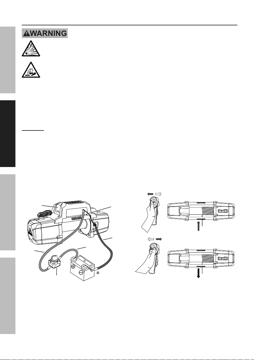
Refer to Figure C.
Disconnect
Switch
Black
Ground
Cable
Red
Battery
Cable
12"
Cable
Socket
Cover
Small
Black
Wire
Figure C: Wiring Connections
4. Attach the 12" 2AWG Disconnect Switch Cable
to the positive terminal on the battery.
5. Attach the 12" 2AWG Cable from the battery
to either terminal on the Disconnect Switch.
6. Attach the red Battery Cable from the Winch to
the remaining terminal on the Disconnect Switch.
7. Attach the black Ground Cable and the Small Black
Wire to the terminal at the rear of the Winch.
8. Attach the black Ground Cable from the Winch
directly to the negative terminal of the battery.
9. Lift the Socket Cover exposing the Remote Control
socket and Wireless Receiver Switch. Connect
the Remote Control Cable to the socket and the
Remote for wired remote control. For wireless
control do not use the Remote Control Cable and
turn on the Wireless Receiver Switch. Refer to
Remote Control Instructions on page 12.
10. Turn on the Disconnect Switch and operate the
remote controls briefly to test Winch function
and drum rotation direction. If operation is
reversed, the Battery Cables may be connected
backwards. Correct any such issue before use.
IN
OUT
Figure D: Remote Controls
11. Disconnect and turn off the Remote
Control when not in use.
12. Turn off the Disconnect Switch when the
Winch is not in use or when the vehicle
has returned to on-highway operation.