Optimus IF-7P4ETH/0 User manual


0
9I334A 06/10/2020 V5.0.002

IF-7P4ETH version 5.0.002 EN
2
IP Audio Interface
with 4 slot for power amplifier modules
allocate 4 amplifiers
IF-7P4ETH/0
4ETH
R + D Department
Table of contents
1. INTRODUCTION ......................................................................................................................................4
2. FRONT VIEW...........................................................................................................................................5
3. REAR VIEW.............................................................................................................................................6
3.1. Control module .....................................................................................................................................7
4. PLACEMENT OF THE BATTERY .................................................................................................................8
5. CONNECTION .........................................................................................................................................9
5.1. IP Connection........................................................................................................................................9
5.2. Connection in installations with a redundant Ethernet network ...........................................................9
5.3. Speakers connection ...........................................................................................................................10
5.4. Local Audio Inputs...............................................................................................................................12
5.5. Power supply ......................................................................................................................................13
5.6. Input contacts .....................................................................................................................................14
5.7. Output contacts ..................................................................................................................................14
5.8. BUS CAN connection ...........................................................................................................................14
5.8.1. Connection of peripherals NS-CAN to the IF-7P4ETH/0.......................................................... 14
5.8.2. CAN Bus connection between the IF-7P7ETH/0 and the IF-7P4/0E slave units ...................... 15
5.9. Connection between the IF-7P4ETH/0 and the IF-7P4/0E slave units using the IF-PLINK expansion
module (not included) ................................................................................................................................15
5.10. Front USB connector: Playing music from an external memory ......................................................16
6. INSERTING THE POWER AMPLIFIERS MODULES .....................................................................................16
7. COMMISSIONING THE UNIT ..................................................................................................................19
7.1. Configuration of the IF-7P4ETH/0 network addresses.........................................................................21
7.2. Configuration of the CAN bus communication speed ..........................................................................22
8. DISPLAY AND FRONT PANEL OPERATION...............................................................................................23
8.1. Structure of the menus .......................................................................................................................23
8.2. Operations from the front pannel .......................................................................................................24
8.2.1. Check the firmware version .................................................................................................... 24
8.2.2. Check the IP address and gateway.......................................................................................... 24
8.2.3. Display of alarms ..................................................................................................................... 24
8.2.4. Canceling an alarm .................................................................................................................. 24
8.2.5. Cancellation of all alarms ........................................................................................................ 24

IF-7P4ETH version 5.0.002 EN
3
IP Audio Interface
with 4 slot for power amplifier modules
allocate 4 amplifiers
IF-7P4ETH/0
4ETH
R + D Department
8.2.6. Modify the volume of the zones ............................................................................................. 24
8.2.7. Mute a zone ............................................................................................................................ 24
8.2.8. Disable a zone ......................................................................................................................... 24
9. SYSTEM ALARMS ..................................................................................................................................24
10. TECHNICAL CHARACTERISTICS...............................................................................................................25
11. MODULAR AMPLIFIERS MP-WD1 SERIES................................................................................................26
12. COMPACT SYSTEM NETWORK SPECIFICATIONS......................................................................................27
13. SOFTWARE AND FIRMWARE VERSIONS .................................................................................................30
14. DOCUMENT VERSION TRACKING...........................................................................................................30
15. GUARANTEE .........................................................................................................................................31
WARNING. This is a Class A unit. In a domestic environment this unit may cause radio interferences. In this case the user
must take the necessary precautions.

IF-7P4ETH version 5.0.002 EN
4
IP Audio Interface
with 4 slot for power amplifier modules
allocate 4 amplifiers
IF-7P4ETH/0
4ETH
R + D Department
1. INTRODUCTION
Audio interface with IP connection for COMPACT system.
It has four slots that allow to insert module amplifiers from MP-WD1* series (not included) and four local analog inputs (program
/priority) of configurable sensitivity.
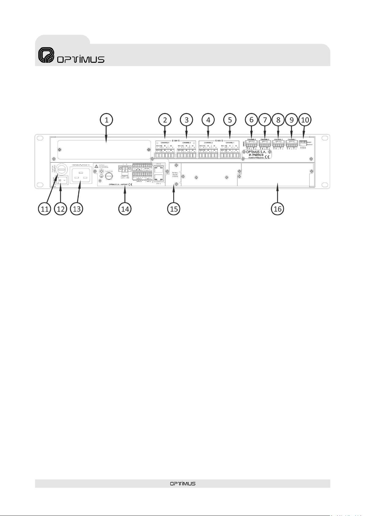
Each zone output has connections for A / B lines (not implemented) and input for backup amplifier.
*Module amplifiers available: 120 W, 150 W, 250 W, 300 W & 460 W
Main characteristics:
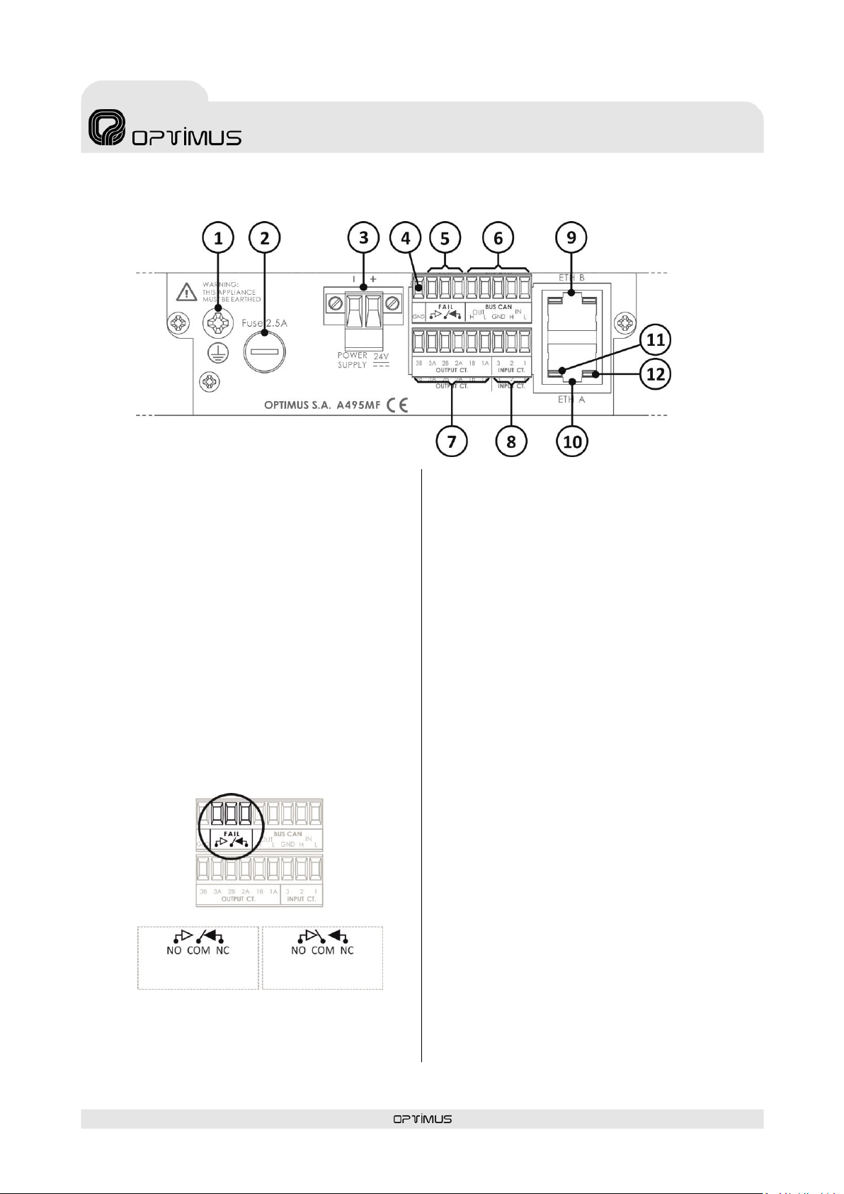
Dual Ethernet connection for installations with redundant
network systems. The connection is constantly monitored
and switches automatically when required.
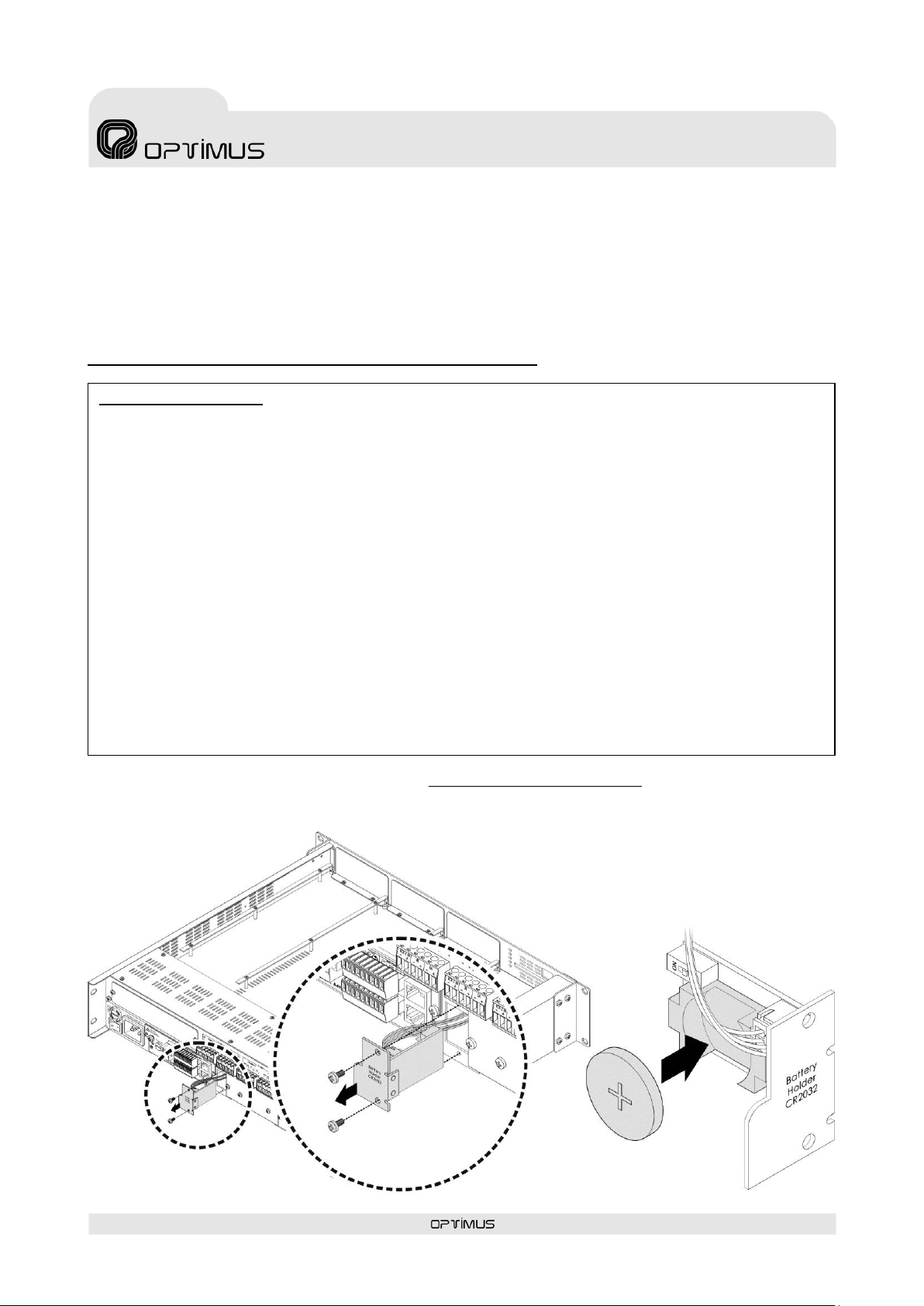
It is equipped with a full range power supply (100-240Vac
50/60 Hz) as well as a secondary battery 24 VDC (only for
the control part).
Four amplifiers outputs that incorporates DSP and
monitoring functions.
DSP functions:
-Controls for volume, bass and treble or 10 band filter
through the Call Point 3.2 software.
Monitoring functions:
-Monitoring of the speaker line: To accomplish this the
equipment injects different frequencies in the speaker
line; it then collects and analyses these frequencies to
determine the condition of the line (line open, short-
circuit, low impedance, high impedance or line in good
condition).
-Monitoring of the condition of the amplifier by
analysing the audio signal to detect if the power stage
has entered into protection mode or is turned off.
Front USB input for local BGM music.
CAN bus for communicating with the peripherals
(NS-CAN.
Reception of digital audio via an IP connection (4
simultaneous channels).
Reception and sending of control data via an IP
connection.
Monitoring of the operation of the equipment using
software and/or basic TELNET or SSH (Secure Shell)
functions.
Configuration of the IP address in Flash memory via
software and web page.
Constant notification (IP) of the status of the equipment
via a Heart Beat signal.
Pre-recorded messages residing in the equipment that
can be remotely updated using the Call Point software via
IP located in the internal Micro SD memory (16 GB).
Monitoring functions:
-of the speaker lines (short-circuit, open line and ground
leakage).
-of the amplifiers.
-of the primary and secondary power supplies.
-of the input contacts.
-of the pre-recorded messages.
Communication with external systems:
-VoIP: receiving of direct calls from any VoIP digital
telephone that uses standard SIP protocols.
Incorporates zone selection by sending DTMF tones.
Provides the possibility of protecting the access with a
password.
-Direct integration (XML, API/DLL and SNMP).
Allows housing module ME-200D (front evacuation
panel).

IF-7P4ETH version 5.0.002 EN
5
IP Audio Interface
with 4 slot for power amplifier modules
allocate 4 amplifiers
IF-7P4ETH/0
4ETH
R + D Department
2. FRONT VIEW
1. Slot 1 for amplifier module (amplifier not included).
2. Slot 2 for amplifier module (amplifier not included).
3. Slot 3 for amplifier module (amplifier not included).
4. Slot 4 for amplifier module (amplifier not included).
5. Amplifier module POWER LED indication.
6. Amplifier module STANDBY LED indication.
7. Amplifier module PROTECT LED indication.
8. Amplifier module CLIP LED indication.
9. Amplifier module SIGNAL LED indication.
10. Display.
11. INPUT CONTACT activation LEDs.
12. OUTPUT CONTACT activation LEDs.
13. Navigation keys and OK/CANCEL selection.
14. GENERAL FAULT LED.
15. SYSTEM FAULT LED.
16. EMERGENCY LED. Red LED emergency indicator. Remains
illuminated while the system is in Emergency Mode.
17. Internal jumper for deactivating the acoustic alarm in
SYSTEM FAULT errors (see section 9).
18. CONSOLE connector. Mini USB connector Allows
monitoring the system. Only specialised personnel
19. POWER SUPPLY LED.
20. Front USB for inputting music.
21. Buzzer. Acoustic alarm.
22. Front blank plate. Allows adding ME-200D module
(evacuation panel).
Figure 1

IF-7P4ETH version 5.0.002 EN
6
IP Audio Interface
with 4 slot for power amplifier modules
allocate 4 amplifiers
IF-7P4ETH/0
4ETH
R + D Department
3. REAR VIEW
1. Surety paging options module space (not included).
2. Speakers line output connection for CHANNEL 4 (lines 4A and 4B*) and 100V input of the BACKUP 4 amplifier.
3. Speakers line output connection for CHANNEL 3 (lines 3A and 3B*) and 100V input of the BACKUP 3 amplifier.
4. Speakers line output connection for CHANNEL 2 (lines 2A and 2B*) and 100V input of the BACKUP 2 amplifier.
5. Speakers line output connection for CHANNEL 1 (lines 1A and 1B*) and 100V input of the BACKUP 1 amplifier.
6. Input CHANNEL 4. Local audio input of slot 4 amplifier.
7. Input CHANNEL 3. Local audio input of slot 3 amplifier.
8. Input CHANNEL 2. Local audio input of slot 2 amplifier.
9. Input CHANNEL 1. Local audio input of slot 1 amplifier.
10. PROGRAM/PRIORITY DIP switches. Program/priority configuration of analog local inputs.
11. Mains fuse (15A).
12. ON/OFF Switch.
13. 100-240V AC 50/60 Hz Power entry connector.
14. Control module. See section 3.1.
15. Battery compartment. See section 4.
16. Expansion module space (not included). Space for the IF-PLINK expansion module (not included). This module is necessary to be
able to expand the capacity of the IF-7P4ETH by adding IF-7P4/0E slave units (see section 5.9).
17.
Figure 2
* A/B Lines functionality not implemented

IF-7P4ETH version 5.0.002 EN
7
IP Audio Interface
with 4 slot for power amplifier modules
allocate 4 amplifiers
IF-7P4ETH/0
4ETH
R + D Department
3.1.Control module
1) Ground connection
2) FUSE. 2.5 A Secondary power supply fuse.
3) POWER SUPPLY 2
24 VDC secondary power input. ONLY Mainframe supply.
4) GND Contact
5) FAIL Contacts
Output relay used to indicate a system failure.
If the COM contact is linked to the NO contact, it indi-
cates that there are no faults or alarms in the system. If
on the other hand, COM is linked to NC, it indicates that
the equipment is switched off or that alarms were de-
tected (figure 4).
Maximum DC charge current: 150 mA
Maximum DC or AC peak charge voltage: 350 V
6) BUS CAN Contacts
Data communication bus between the IF-7P4ETH/0 and
the system peripherals (NS-CAN), or between the
IF-7P4ETH/0 and the slave units IF-7P4/0E.
7) OUTPUT Contacts CT 1, 2 and 3
Incorporates three output contacts configured as dry
contacts. Each contact has two terminals (A and B).
The functionality and stand-by state (NC/NO) are
configured through the Call Point software. They may be
configured as general purpose contacts or in the
evacuation system as fault notification contacts,
Emergency Mode indicator activated...
8) INPUT Contacts CT 1, 2 and 3
Incorporates three input contacts.
The functionality and stand-by state (NC/NO) are
configured through the Call Point software. They may be
configured as general purpose contacts or in the
evacuation system as emergency mode activation
contacts, evacuation message activated...
The detection time of the activation pulse of the input
contacts is configurable through the Call Point software
(0-50-100-200-300-400-500-1000-1500-2000
milliseconds).
If you wish, the system may monitor these contacts
(short-circuit or open line detection).
9) ETH B Connector
Is used in a redundant network as a secondary
connection to the IP network.
10) ETH A Connector
Is used to connect the unit to the IP network.
11) LINK/ACTIVITY indicator (green LED):
When illuminated it indicates a network connection.
When flashing it indicates that data is being sent or
received.
12) SPEED indicator (yellow LED):
Speed of the network. If the LED is lit, indicates a speed
of 100 Mbps. If unlit, indicates a network speed of 10
Mbps (it is highly recommended to use a transmission
speed of 100 Mbps).
Figure 3
Figure 4
No alarms
Device is turned off or
alarms detected
FAIL RELAY STATUS

IF-7P4ETH version 5.0.002 EN
8
IP Audio Interface
with 4 slot for power amplifier modules
allocate 4 amplifiers
IF-7P4ETH/0
4ETH
R + D Department
Handling batteries properly:
•Warning! Improper use of battery may lead to explosion. Replace the batteries with the same or equivalent type only.
•Batteries may endanger life if swallowed. If a battery is swallowed, seek medical assistance immediately.
•Before inserting the batteries, check whether the contacts in the device and batteries are clean and, if necessary, clean
them.
•Only use new batteries.
•Do not use rechargeable batteries
•Never try to recharge normal batteries. There is a risk of explosion!
•Never expose batteries to heat sources (e.g. radiators) or direct sunlight. There is an increased risk of leakage!
•Never short-circuit the batteries.
•Never throw batteries into a fire.
•Do not disassemble or deform batteries.
•If the equipment is not going to be used for long periods, remove the battery.
•Remove leaking batteries from the device immediately. If battery acid leaks out it is essential to avoid contact with the skin,
eyes and mucous membranes! If the acid does come into contact with skin, immediately rinse the affected areas with plen-
ty of clear water and consult a doctor immediately. There is a risk of acid poisoning and acid burns!
•Remove exhausted rechargeable battery from the device immediately! There is an increased risk of leakage
•Do not throw used batteries into the household waste. The batteries must be deposited in a collection point for used bat-
teries.
4. PLACEMENT OF THE BATTERY
From the Call Point software it is possible to create message time schedules and volume time schedules, and send these schedules
to the equipment. In this way, it is not necessary a server PC to activate the time schedules, but it is the computer that activates
them automatically.
To do this, the equipment incorporates an RTC (Real-Time Clock) whose function is to maintain the current time. To keep the RTC
powered even if the equipment is turned off, we must place a 3V lithium battery type CR2032 supplied with the equipment.
It is advisable to replace the equipment battery at least every 5 years.
Battery placement procedure:
1) Open the battery compartment by removing the screws that hold it.
2) Insert the battery respecting the polarity indicated in the figure 5.
3) Insert the battery compartment in its place and fix it with the
screws.
Figure 5

IF-7P4ETH version 5.0.002 EN
9
IP Audio Interface
with 4 slot for power amplifier modules
allocate 4 amplifiers
IF-7P4ETH/0
4ETH
R + D Department
5. CONNECTION
5.1.IP Connection
5.2.Connection in installations with a redundant Ethernet network
Connection to the Ethernet
switch 2
Connection to the Ethernet
switch 1
Connection to the Ethernet
switch
Figure 6
Figure 7

IF-7P4ETH version 5.0.002 EN
10
IP Audio Interface
with 4 slot for power amplifier modules
allocate 4 amplifiers
IF-7P4ETH/0
4ETH
R + D Department
5.3.Speakers connection
The equipment has four channels (one per amplifier) for the connection of 100V high impedance speaker lines.
Each channel has connections for A / B lines for installations with redundant loudspeaker lines (not implemented) and a backup
amplifier input.
Figure 8
4 ZONES SPEAKER LINES CONNECTION
IF-7P4ETH/0
ZONE
AMPLIFIER
ZONE
AMPLIFIER
ZONE
AMPLIFIER
ZONE
AMPLIFIER

IF-7P4ETH version 5.0.002 EN
11
IP Audio Interface
with 4 slot for power amplifier modules
allocate 4 amplifiers
IF-7P4ETH/0
4ETH
R + D Department
WARNING:
The sum of the power ratings of the loudspeakers connected to output of an amplifier must not exceed the
power of the amplifier module.
The backup amplifier must be at least the most powerful of the amplifiers you must replace.
Figure 9
SPEAKER LINES CONNECTION
3 ZONE AMPLIFIERS + 1 BACKUP AMPLIFIER
IF-7P4ETH/0
BACKUP
AMPLIFIER
ZONE
AMPLIFIER
ZONE
AMPLIFIER
ZONE
AMPLIFIER

IF-7P4ETH version 5.0.002 EN
12
IP Audio Interface
with 4 slot for power amplifier modules
allocate 4 amplifiers
IF-7P4ETH/0
4ETH
R + D Department
5.4.Local Audio Inputs
Each of the inputs corresponds to a channel (CHANNELS 1, 2, 3 and 4), and each channel corresponds to an amplifier. In this way,
the CHANNEL 1 input corresponds to the amplifier inserted in slot 1, the CHANNEL 2 input corresponds to the amplifier inserted in
SLOT 2, the CHANNEL 3 input corresponds to the amplifier inserted in SLOT 3 and the CHANNEL 4 input corresponds to the
amplifier inserted in SLOT 4.
These inputs are balanced by transformer, with a configurable sensitivity using the Call Point software: -6dB, -3dB, 0dB, + 3dB, +
6dB.
With a DIP switch, the local inputs can be configured as program or priority inputs. In the PROGRAM position, the audio applied to
the input is sent directly to the amplifier of the corresponding channel. In the PRIORITY position, the audio applied to the input will
be sent to the corresponding amplifier when the priority contact (PRI) is connected to ground (GND).
Figure 10
Figure 11
H
HOT Audio input
GND
Ground
C
COLD Audio input
PRI
Priority control contact. By joining this
contact to ground (GND) through an
external device, the signal applied to
the input attacks the corresponding
amplifier.
ACK
Acknowledge output contact. By
closing that contact the equipment
confirms that the priority channel is
activated and ready

IF-7P4ETH version 5.0.002 EN
13
IP Audio Interface
with 4 slot for power amplifier modules
allocate 4 amplifiers
IF-7P4ETH/0
4ETH
R + D Department
5.5.Power supply
The equipment has a 100-240VAC power input which allows the connection of the equipment to the mains by means of the
supplied cable.
If required, a secondary power supply input of 24 VDC that will supply ONLY the control module of the mainframe.
PRIMARY
POWER SUPPLY
SECONDARY
POWER SUPPLY
24VDC POWER SUPPLY
I924UP
(Not included)
Figure 14
Figure 12
Balanced audio connection
to a local audio input of the IF-7P4ETH / 0
Figure 13
Unbalanced audio connection
to a local audio input of the IF-7P4ETH / 0
AUDIO –
AUDIO +
GROUND
AUDIO +
GROUND
External
equipment
External
equipment

IF-7P4ETH version 5.0.002 EN
14
IP Audio Interface
with 4 slot for power amplifier modules
allocate 4 amplifiers
IF-7P4ETH/0
4ETH
R + D Department
5.6.Input contacts
The IF-7P4ETH/0 incorporates three input contacts (INPUT CT 1, 2 and 3).
If you wish, the system may monitor these contacts (short-circuit or open line detection).
5.7.Output contacts
The IF-7P4ETH/0 incorporates three output contacts.
Each contact has two terminals (A and B) configured as dry contacts.
5.8.BUS CAN connection
For the connection of the CAN bus it is recommended to use a shielded twisted pair AWG24 cable.
5.8.1. Connection of peripherals NS-CAN to the IF-7P4ETH/0
Attention: The factory setting of the
communication speed of the IF-7P4ETH/0
is 500 kbit/s. To communicate with the
NS-CAN noise sensors, it is necessary to
modify the communication speed of the
IF-7P4ETH/0 via web connection from 500
kbit/s to 33.3 kbit/s (see section 7.2).
INPUT CONTACT CONNECTION
WITHOUT SURVEILLANCE
INPUT CONTACT CONNECTION
WITH SURVEILLANCE
EXTERNAL
EQUIPMENT
Figure 15
Figure 16
Figure 17
Figure 18
PERIPHERAL
(NS-CAN)
(Not connected)

IF-7P4ETH version 5.0.002 EN
15
IP Audio Interface
with 4 slot for power amplifier modules
allocate 4 amplifiers
IF-7P4ETH/0
4ETH
R + D Department
5.8.2. CAN Bus connection between the IF-7P7ETH/0 and the IF-7P4/0E slave units
The capacity of each IF-7P4ETH/0 (4 modular amplifiers) can be expanded by adding to the installation IF-7P4/0E slave units, with
the capacity of 4 amplifiers per slave.
Each IF-7P4ETH/0 can control up to
10 IF-7P4/0E slave units,
communicating through a CAN bus.
The IF-7P4ETH/0 communicates
with the slave units IF-7P4/0E at a
transmission speed of 500 kbit/s.
The factory setting of the
communication speed of the
IF-7P4ETH/0 is 500 kbit/s.
Use the web connection if it is
necessary to change the
communication speed of the
IF-7P4ETH/0 (see section 7.2).
5.9.Connection between the IF-7P4ETH/0 and the IF-7P4/0E slave units using the IF-PLINK
expansion module (not included)
Use the AUDIO LINK connectors to connect the different audio matrices, expanding the audio bus (see figure 20). It is also
necessary to connect the CAN Bus between the matrices (see figure 19).
Figure 20
(CAN Bus) (Audio Bus)
IF-7P4ETH/0
IF-7P4/0E
IF-7P4/0E
IF-PLINK
IF-7P4ETH/0
IF-7P4/0E
IF-7P4/0E
Figure 19

IF-7P4ETH version 5.0.002 EN
16
IP Audio Interface
with 4 slot for power amplifier modules
allocate 4 amplifiers
IF-7P4ETH/0
4ETH
R + D Department
5.10. Front USB connector: Playing music from an external memory
The unit has a USB 2.0 port on the front panel for use as a musical program input. To do this, connect to this port an external
memory that contains audio files in MP3, WAV or OGG format. Audio files can be contained in folders or directly at the root of
external memory.
Through the Call Point software you can configure the parameters corresponding to this music program (random playback of audio
files, music activated or deactivated by zones...). If random play is not activated, audio files will be played in alphanumeric order.
6. INSERTING THE POWER AMPLIFIERS MODULES
1. Remove the frontal plate.
Figure 21
Figure 22

IF-7P4ETH version 5.0.002 EN
17
IP Audio Interface
with 4 slot for power amplifier modules
allocate 4 amplifiers
IF-7P4ETH/0
4ETH
R + D Department
2. If you want to use slots 2, 3 or 4, remove
the corresponding slot panel.
3. Insert the amplifier module by fitting it
into the slot guides.
Figure 23
Figure 24

IF-7P4ETH version 5.0.002 EN
18
IP Audio Interface
with 4 slot for power amplifier modules
allocate 4 amplifiers
IF-7P4ETH/0
4ETH
R + D Department
3. Fasten the amplifier module by means of the hot-swapping screw.
4. Finally, fix the front plate.
Figure 25
Figure 26
Table of contents
Languages:
Other Optimus Recording Equipment manuals
Popular Recording Equipment manuals by other brands

Overstayer
Overstayer SATURATOR NT-02A user guide

ESD electronic
ESD electronic CAN-PCI/360 Hardware installation and technical data

Whadda
Whadda WPI437 user manual

BSS Audio
BSS Audio Soundweb London BLU-800 installation guide

SKP Pro Audio
SKP Pro Audio DSP-4 owner's manual

Heinzmann
Heinzmann LMG-IF 02 manual