manuals.online logo
Brands
  1. Home
  2. •
  3. Brands
  4. •
  5. Lowell
  6. •
  7. Recording Equipment
  8. •
  9. Lowell SEQR-4 User manual

Lowell SEQR-4 User manual

Lowell strives to provide accurate information while reserving the right to change specications and/or improve manufacturing methods without prior notication.
©2021 Lowell Manufacturing Co., 100 Integram Dr., Pacic MO 63069 / tel. 800.325.9660 / www.lowellmfg.com
Spec 1604
Model SEQR-4 Rev. 02-02-21 | pg. 1/3
The low voltage rackmount sequencer is used in conjunction with
remote power controls (RPCs) to provide time-delayed activation
and deactivation of connected equipment, often located in another
rack, room or building. The sequencer can also control accessory
systems such as projector screens, lighting or blinds. To initiate
sequencing, use the rocker switch on the front panel or connect
an external switch to the rear terminal block for remote activation.
Note: This sequencer is for use with compatible components that feature classic
connections. It is not for use with devices that feature pass-through connections.
FEATURES:
• Power Requirement: 100-240VAC 500mA max.
• Rackmount Chassis: 19" x 9" x 1.75" steel chassis with black
powder epoxy nish.
• Activation Trigger:
– Rocker Switch: Sequencing is typically initiated by the front
rocker switch. Activation in mid-cycle reverses direction.
– Remote Switch (optional): External switch(es) with
MOMENTARY closure can be connected to the rear barrier
strip terminal block to initiate sequencing. Up to eight
momentary switches can be connected in parallel.
• Four Step Sequencer:
– The rear has four barrier strip control outputs that activate in
sequential order (1, 2, 3, 4) and deactivate in reverse order.
– The delay between steps can be adjusted (0.5-10 seconds)
via a trimpot on the front panel.
– LEDs provide visual status of the activation sequence. A green
LED ashes when the system is cycling up and remains
steady when the system is on. The red LED ashes when the
system is cycling down and remains steady when the system
is off.
– Includes auxiliary 24VDC output (300mA max.) for use with
remote indicators, if needed.
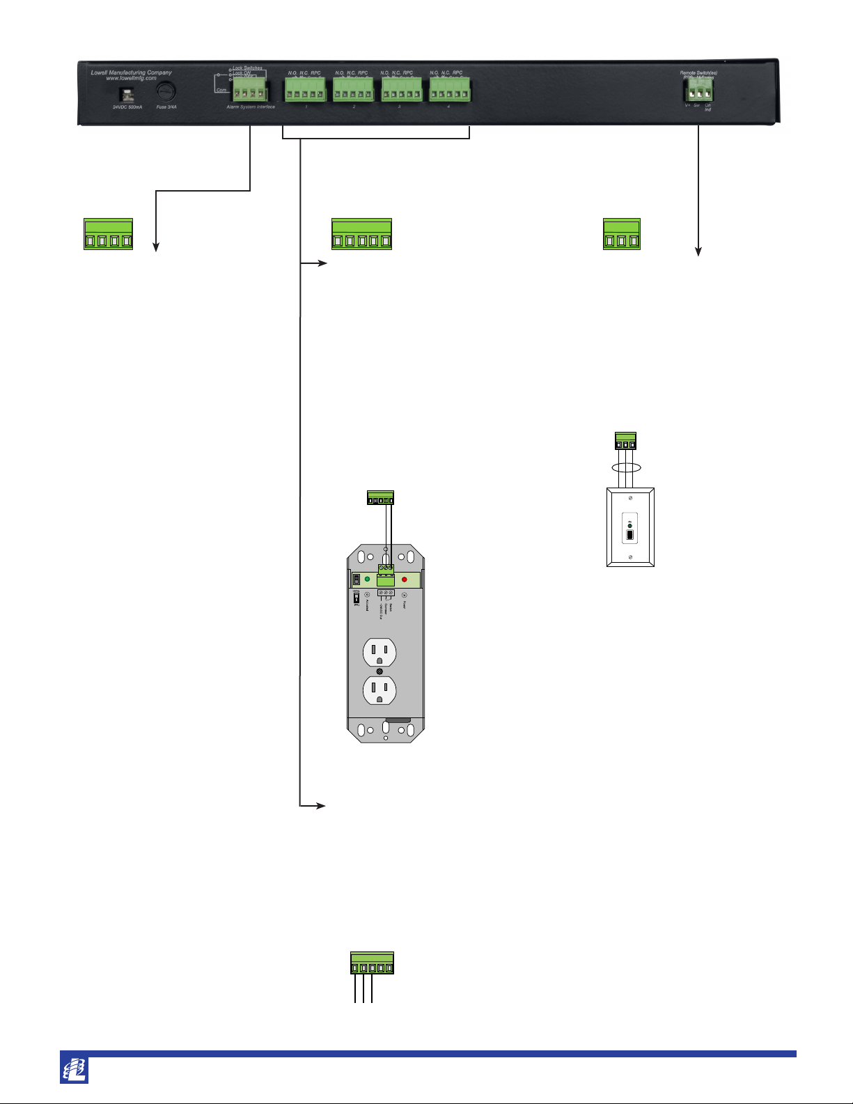
• Rear Connections: Plug-in barrier strip terminal block. See
installation drawings on page two.
– Input from Alarm System Interface: System switches can be
overridden by contact closures provided on a fire alarm panel
or a similarly installed device. Make one contact only (Lock
Off, Lock On, or Switch Lock).
– Output to RPC and/or Accessory System (steps 1-4):
+ To sequentially activate equipment, connect the Common
and Switched Relay contacts on an output to a remote
power control, then plug the equipment in to the RPC.
Each output can control up to ten RPCs.
+ To sequentially activate an accessory system or indicator,
connect dry contacts (N.O., N.C., Com.) on an output to the
accessory device.
– Input from Remote Switch(es): Connect Lowell remote
switch(es) that have MOMENTARY closure and one LED. Up
to eight switches can be connected in parallel.
• Power Supply: UL Listed power supply (100-240VAC input,
24VDC 500mA output) with 6 ft. cord and NEMA 1-15P plug.
Includes three adaptors for international use (Schuko CEE 7/16,
BS1362, AS3112).
• Country of Origin: Made in U.S.A. with global components
•
A&E Specications: The sequencer shall be Lowell model
SEQR-4, which shall feature a front rocker activation switch,
trimpot for four-step delay adjustment of sequence operation
(1/2 to 10 sec.), and LED status indicators. The rear shall feature
barrier strip terminals to connect Lowell remote power controls,
dry auxiliary contacts to connect accessory devices, contacts to
connect an external remote momentary style switch, and an alarm
system interface. The 19" x 9" x 1.75" rackmount chassis shall
be steel with black powder epoxy nish. The sequencer shall be
made in the U.S.A. with global components. It shall include a
power supply with 100-240VAC input, 24VDC 500 mA output,
and six ft. power cord with four plug adaptors.
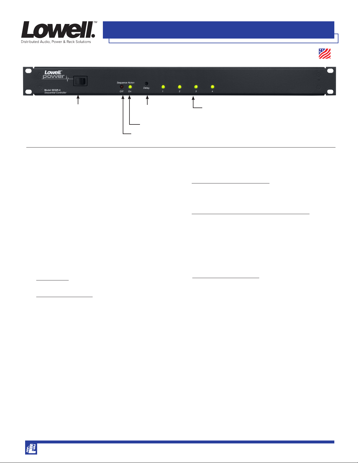
Rackmount Sequencer (4 step): SEQR-4
Red LED: FLASHING = down cycle in progress; STEADY ON = down cycle completed (system off)
Green LED: FLASHING = up cycle in progress; STEADY ON = up cycle completed (system on)
Rocker Switch: starts sequence
up or down. Activation in mid-cycle
reverses direction.
Delay Adjust:
recessed trim pot
Four LEDs: light to indicate progress of sequence (up or down).
Made in USA
Lowell strives to provide accurate information while reserving the right to change specications and/or improve manufacturing methods without prior notication.
©2021 Lowell Manufacturing Co., 100 Integram Dr., Pacic MO 63069 / tel. 800.325.9660 / www.lowellmfg.com
Spec 1604
Model SEQR-4 Rev. 02-02-21 | pg. 2/3
Step 1 Step 2 Step 3 Step 4
Includes power supply
ALARM SYSTEM INTERFACE:
If required by local building code, facility
usage, or the Fire Marshal; the system
functions can be overridden and the
system controlled by contact closures
provided by the re alarm panel or other
similarly installed device. A maintained
contact between the ‘com’ terminal and
any of the terminals shown will provide
the following functions.
CAUTION: Do not allow alarm system
to make more than one of the following
contacts at the same time—controller
board damage may result.
• Lock Off: A maintained contact
between the ‘com’ terminal and the
‘lock off’ terminal will turn the system
off and keep it off regardless of other
switch activations. If the system is
already off, it will remain off.
• Lock On: A maintained contact
between the ‘com’ terminal and the
‘lock on’ terminal will turn the system
on and keep it on regardless of other
switch activations. If the system is
already on, it will remain on.
• Switch Lock: A maintained contact
between the ‘com’ terminal and the
‘switch lock’ terminal will lock the
system in its current state, either on
or off, regardless of any other switch
activations.
RPC CONNECTIONS:
Connect equipment to Lowell RPC Series
remote power controls that feature classic
connections (not pass-through), and connect
the RPCs to one of the four steps on the
sequencer using two connectors (Common,
Switched Relay). The sequencer allows up to
10 RPCs to be connected in parallel on each
of the four circuits.
NOTE:
Common connections from multiple RPCs
controlled by different sequence steps can be
consolidated into one conductor and connected to
any common terminal at the sequencer.
REMOTE SWITCH CONNECTIONS:
Lowell RPS Series switches with
MOMENTARY closure and a single LED can
be connected to control the sequencer from
remote locations. Up to eight switches may
be connected in parallel. Select switches with
rocker or key activation.
Maximum wire distances:
24-gauge = 20,000 ft.; 22-gauge = 31,200 ft.;
18-gauge = 76,800 ft.
RPC Series remote power controls
use two connectors (common,
switched relay)
Accessory systems contacts
(normally open, common, normally closed).
RPS Series MOMENTARY switches
that feature one LED use three
connectors.
Ind.
Switch
V+
Lock Switches
Lock ON
Lock OFF
Com
Common
Switched Relay
Normally Closed
Common
Normally Open
Ind.
Switch
V+
Lock Switches
Lock ON
Lock OFF
Com
Common
Switched Relay
Normally Closed
Common
Normally Open
Ind.
Switch
V+
Lock Switches
Lock ON
Lock OFF
Com
Common
Switched Relay
Normally Closed
Common
Normally Open
AUXILIARY DRY CONTACTS:
Each of the four outputs features accessory
contacts (Normally Open, Common, Normally
Closed) with contact rating of 5A max. for
connection to accessory systems or indicator
devices (projector screens, lighting, blinds, etc.)
Common
Switched Relay
Normally Closed
Common
Normally Open
Common
Switched Relay
Normally Closed
Common
Normally Open
Ind.
Switch
V+
Lowell strives to provide accurate information while reserving the right to change specications and/or improve manufacturing methods without prior notication.
©2021 Lowell Manufacturing Co., 100 Integram Dr., Pacic MO 63069 / tel. 800.325.9660 / www.lowellmfg.com
Spec 1604
Model SEQR-4 Rev. 02-02-21 | pg. 3/3
This
spec
SEQ & SEQR Series Overview — sequencers with classic connections
Alternate
REQUIRES ACCEPTS ACCEPTS ACCEPTS
Sequence Onboard A Remote Multiple Remote Input from Input from Lowell Power Country
Model No. Chassis Steps Mode Switch Switch Switches Alarm System Switch w/RJ45 Input of Origin
SEQ-4 standalone 4 --- --- yes through
MSM2
--- --- power supply USA
SEQ-8 standalone 8 --- --- yes yes --- --- power supply USA
SEQR-4 1U panel 4 --- rocker --- yes yes --- power supply USA
SEQR-4K 1U panel 4 --- key --- yes yes --- power supply USA
SEQR-8 1U panel 8 yes rocker --- yes yes --- power supply USA
SEQR-8K 1U panel 8 yes key --- yes yes --- power supply USA
SEQR-8RJ 1U panel 8 yes rocker --- yes yes yes power supply USA
Steps = Unit activates/deactivates connected remote power controls (RPCs) in four or eight steps, with a delay between each. Multiple RPCs can connect to each step.
Alternate Sequence Mode = The ASM feature skips selected outputs to allow partial startup of system, useful for small events or rehearsals. It requires remote switch
model RPSB-KP-ASM to enable ASM function before main switch is activated.
Onboard Switch = Sequencers without an onboard switch will require an external switch for activation.
REQUIRES A Remote Switch = Sequencer can be controlled by one external switch, usually placed in a remote location (RPS series switch with MAINTAINED closure).
ACCEPTS Multiple Remote Switches = Sequencer can be controlled by one or more external switches placed in remote locations (RPS Series switches with
MOMENTARY closure). Some models require the MSM2 module in order to accept multiple switches.
ACCEPTS Input from Alarm System = Sequencer can accept control override from an alarm system (alarm by others, not included).
ACCEPTS Input from Lowell Switch w/RJ45 = Sequencer is designed for use with a Lowell MOMENTARY switch that has a model number with "-RJ" as a suffix (see
options above). Note that these switches include a single RJ45 connector and are not part of Lowell's "pass-through" series.
NOTE: See Lowell ACR Series or ACSPR Series for rackmount sequencers that include AC power outlets.
COMPATIBLE COMPONENTS: (order separately)
• REMOTE SWITCHES: (RPS Series with MOMENTARY closure and one LED)
Model Description
RPSW-MP 1 LED rocker switch, white wall plate
RPSB-MP 1 LED rocker switch, black wall plate
RPSB-MR 1 LED rocker switch, 19" panel
RPSW-MKP 1 LED key switch, white wall plate
RPSB-MKP 1 LED key switch, black wall plate
RPSB-MKR 1 LED key switch, 19" panel
• REMOTE POWER CONTROL: (RPC Series with classic connections)
Model Description Model Description
RPC-15 RPC with (2) 15A NEMA outlets, cord RPC-15-S RPC with (2) 15A NEMA outlets, surge supp, cord
RPC-15-U RPC with (2) IEC C13 oulets, cord RPC-20-CD RPC with (2) 20A NEMA outlets, cord
RPC-20-SCD RPC with (2) 20A NEMA outlets, surge supp, cord RPC-3N1 RPC with (8) 15A NEMA outlets, cord
RPC-20-HW RPC with (2) 20A NEMA outlets, whip RPC-20-SHW RPC with (2) 20A NEMA outlets, surge supp, whip
RPC-30-SHW RPC with 30A Twistlock outlets, surge supp, whip
• MISCELLANEOUS:
Model Description
ACS-1510-RPC 30" power strip with ten 15A outlets, RPC function, cord
ACS-2010-RPC-HW 30" power strip with ten 20A outlets, RPC function, hardwired
ACS-2018-5C-RPC-HW 60" power strip with eighteen 20A outlets on ve circuits, RPC function, hardwired
ACSP-1502-RPC Compact surge suppressor with two 15A outlets, RPC function
ACSP-2002-RPC Compact surge suppressor with two 20A outlets, RPC function

Other Lowell Recording Equipment manuals

Lowell SEQ-8 User manual

Lowell

Lowell SEQ-8 User manual

Lowell SEQR-8RJ User manual

Lowell

Lowell SEQR-8RJ User manual

Lowell SEQ-4 User manual

Lowell

Lowell SEQ-4 User manual

Lowell SEQ-4A User manual

Lowell

Lowell SEQ-4A User manual

Lowell EQ1 Assembly instructions

Lowell

Lowell EQ1 Assembly instructions

Popular Recording Equipment manuals by other brands

AMX NetLinx NXP-TPI/4 quick start guide

AMX

AMX NetLinx NXP-TPI/4 quick start guide

Yamaha QY-8 user guide

Yamaha

Yamaha QY-8 user guide

gefran SBI-DN instruction manual

gefran

gefran SBI-DN instruction manual

Pioneer PDR-W739 operating instructions

Pioneer

Pioneer PDR-W739 operating instructions

LST FWI2-1 Specification sheet

LST

LST FWI2-1 Specification sheet

Omnia Omnia.9 Installation & user guide

Omnia

Omnia Omnia.9 Installation & user guide

iCON Pro Audio Mobile-U Live user manual

iCON Pro Audio

iCON Pro Audio Mobile-U Live user manual

Microtech 325 Installation & maintenance data

Microtech

Microtech 325 Installation & maintenance data

SOMFY URTSI 2 Integration guide

SOMFY

SOMFY URTSI 2 Integration guide

abaco systems CEI-100 Series user manual

abaco systems

abaco systems CEI-100 Series user manual

Lynx greenMachine Reference manual

Lynx

Lynx greenMachine Reference manual

Gemtech MK-9K Operation and maintenance

Gemtech

Gemtech MK-9K Operation and maintenance

Vivo VB-01 instruction manual

Vivo

Vivo VB-01 instruction manual

Kramer DSP-62-UC user manual

Kramer

Kramer DSP-62-UC user manual

Klark Teknik dn735 Operating and service information

Klark Teknik

Klark Teknik dn735 Operating and service information

F-Pedals DARKLIGHT user guide

F-Pedals

F-Pedals DARKLIGHT user guide

Audioplex PRO CAT installation manual

Audioplex

Audioplex PRO CAT installation manual

DEVA Deva037 user manual

DEVA

DEVA Deva037 user manual

manuals.online logo
manuals.online logoBrands
  • About & Mission
  • Contact us
  • Privacy Policy
  • Terms and Conditions

Copyright 2025 Manuals.Online. All Rights Reserved.