Hardy Diagnostics The Wizard CompactDry Reader User manual

Operating Instructions

General Information and Warnings............ 1
How to Get the most from your
CompactDry™ plates and The Wizard™
CompactDry™ Reader .................................... 2
Getting Started ................................................. 3
Equipment Overview..................................4-5
General Operation ........................................... 6
User Interface ...............................................7-14
Advanced Configuration
and Passcode ............................................15-20
USB Removal and Power Down ......... 21-22
How to connect to the Hardy Data
Receiver Program ................................... 23-24
Connecting USB Thermal Printer ............25
Accessories.......................................................26
Limitations........................................................27
Specifications ..................................................28
Warranty and Service...................................29
Our Advantage .............................................. 30
Table of Contents
1430 West McCoy Lane
Santa Maria, CA 93455
800.266.2222
HardyDiagnostics.com

1
Technical Support: 800-266-2222, option 2
General Information and Warnings
Notable Symbols and Precautions:
Caution: Read these operating instructions fully before use and pay
attention to sections containing this symbol.
Always observe the safety precautions as specified by the
operating instructions.
• If liquid is spilled inside the unit, immediately disconnect it from the
power supply and contact Technical Support.
• Clean the unit only with a damp cloth; do not use chemical or abrasive
cleaning agents.
• Before moving, disconnect at the power supply socket.
• Connect only to a power supply with voltage corresponding to that on
the serial number label.
• Ensure that the main switch and power supply connector are easily
accessible during use.
• After transport or storage in humid conditions, dry out the unit before
connecting it to the supply voltage.
The Wizard™ CompactDry™ Reader is designed to read and document CompactDry™
culture media plate colony counts with a color interpretation. The Wizard™ Compact-
Dry™ Reader has selectable modes in the configuration menu designed to read the
various types of CompactDry™ plates.

2
How to Get the most from your CompactDry™
plates and The Wizard™ CompactDry™ Reader
Whether your lab is an established CompactDry™ user or in the process of validating its
use, it is important that the proper use of the CompactDry™ plate products will greatly
enhance the performance of The Wizard CompactDry™ Reader. Please note these im-
portant points and refer to the IFU (Instructions For Use) for each of the CompactDry™
plates:
• Carefully read through each section of this manual and the IFU for each Compact-
Dry™ plate, conveniently located within the Hardy website, HardyDiagnostics.com
• Validate sample matrices and adjust settings as needed according to this manual
before use.
• It is highly recommended to use a stomacher bag and filter the homogenized sam-
ple prior to inoculation to eliminate carry over of tiny particles onto the surface of
the CompactDry™ medium. Small particles may interfere with photo optic detection
mechanism.
• During and after incubation, keep the lid tight on the plates to avoid any possible
dehydration.
• An additional dilution may be needed when the sample has a dark color, which is
can be indicative of a high bioburden. Individual colonies may not be distinguishable
on trays if concentrations are above 100 CFU/ml. In general, additional 1:10 dilutions
will allow colonies to be visualized. The Wizard™ CompactDry™ Reader has a maxi-
mum detection limit of 150 CFU; however the sample should be diluted to a concen-
tration of less than 100 CFU/ml for best results. Refer to the procedure section and
general dilution guidelines in the IFU for each plate type.

3
Technical Support: 800-266-2222, option 2
Getting Started
Unpacking
Remove the packing materials carefully, and keep for future shipment or storage
of the unit.
The Wizard™ CompactDry™ Reader includes:
• Reader....................................................................................................1 piece
• Power Supply and international adapters ...............................1 piece
• USB Flash Drive with Hardy Data Receiver Program..........1 piece
• Warranty Card ....................................................................................1 copy
• Operating Instructions ....................................................................1 copy
• Quick Start Guide for setup ..........................................................1 copy
Instrument Placement
1. Place The Wizard™ CompactDry™ Reader on a solid, level surface so that there
is at least 10cm of clearance from adjacent walls. Ensure that the power switch,
USB ports, and the ventilation slots on the side of the unit are free from
obstruction.
2. Ensure the power switch is set to the OFF position
before connecting to the power source.
3. Connect The Wizard™ CompactDry™ Reader to the power supply. Plug power
supply into an appropriate electrical outlet.
4. Switch the unit to the ON position utilizing the power ON/OFF switch located
on the right side of the instrument.
System Accessories
Accessories are available for purchase to suit your laboratory work-flow. See
page 26.
ON
OFF
4
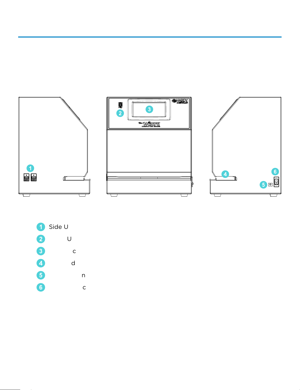
Equipment Overview
Main System Components
6
5
4
3
2
1
1
Side USB Connection (2x)
2
Front USB Connection (1x)
3
Touch Screen Interface
4
Plate Indexing Tray
5
Power Connection Port
6
Power Switch
5
Technical Support: 800-266-2222, option 2
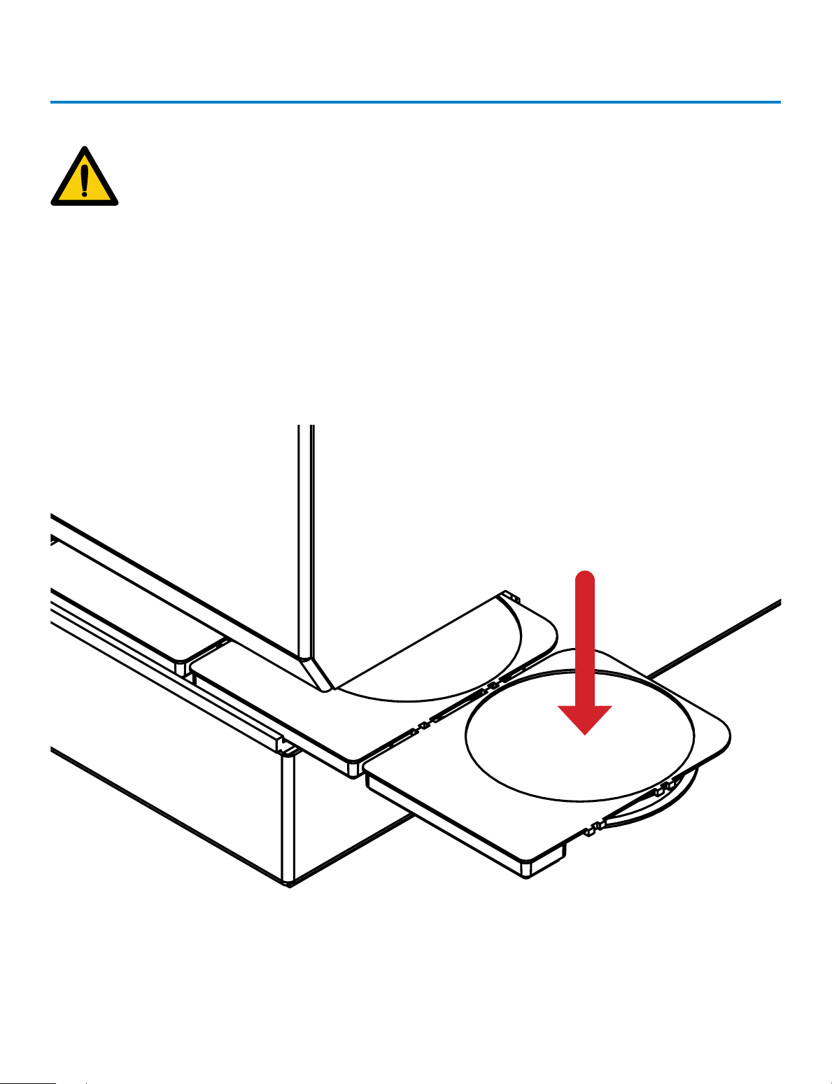
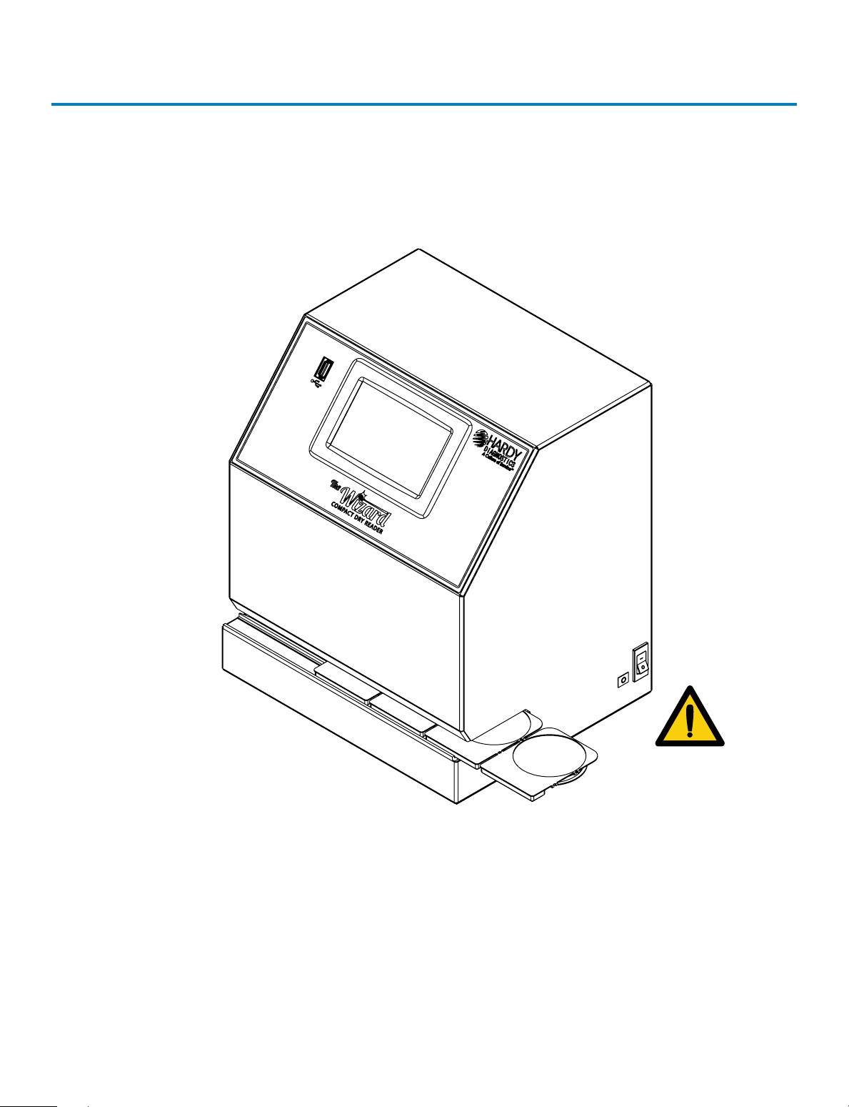
Equipment Overview (continued)
PLATES MUST BE INSERTED WITH THE LIDS
AFFIXED TO THE BASE AND
FACING DOWNWARD. FAILURE TO INSERT
PLATES PROPERLY MAY CAUSE INCORRECT
PLATE COUNTS, SYSTEM ERRORS, DAMAGE,
OR CONTAMINATION.
6
General Operation
The system has been designed to accept and index only CompactDry™ plates.
CompactDry™ plates must be inserted face down with the lids on.
1. Make sure the outside of the plates are dry and free of debris and the plate lids
are securely fitted.
2. Plates can be inserted in connected sets or one at a time.
3. Turn plate(s) so lid is facing down.
4. Hold the CompactDry™ plates by the raised rectangular tab.
5. Slide the plates into the unit from either the right or left hand side.
6. The first plate will “click” into place when positioned correctly for imaging.
Plates face down
with lids on
7
Technical Support: 800-266-2222, option 2
User Interface
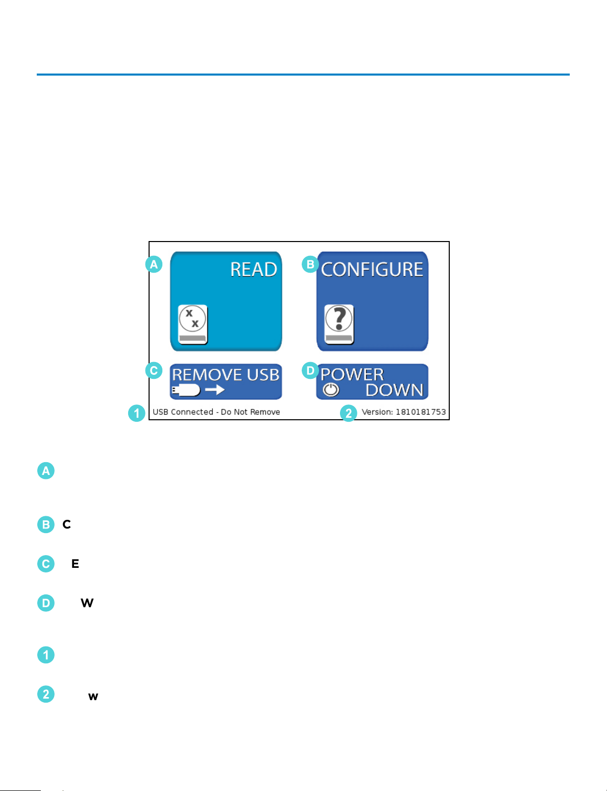
Home Screen Operation
The Home Screen is the first screen displayed after the unit is done initializing upon
powering on. From the Home Screen, the operator can navigate to the Read Screen
where CompactDry™ plates are imaged and analyzed. The operator can also configure
the system and change the sensitivity via the Configure Screen. The Home Screen is
also used to safely remove a USB flash drive.
🇦
READ – Accesses the Read Screen. From the Read Screen, CompactDry™ plates
are imaged, colonies are counted, analyzed, and the data is saved
(complete guide pg. 8).
🇧
CONFIGURE – Used to adjust settings and change the unit data saving settings
(complete guide pg. 13).
🇨
REMOVE USB – Used to safely remove a USB Flash Drive. Errors can occur if the
USB Flash Drive is removed incorrectly (complete guide pg. 21)
🇩
POWER DOWN – Used to properly shut down the unit. Press the power down
button before turning o the main power switch to ensure proper
shutdown (complete guide pg. 22).
1
USB Flash Drive Status – This portion of the screen displays USB Flash Drive
connection status.
2
Software Version Information – This area of the screen displays information on the
system software version.
🇦
🇨
1
🇧
🇩
2
8
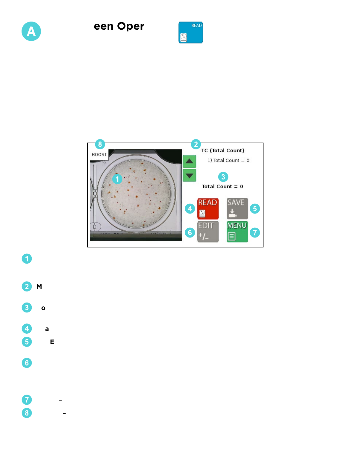
1
Video/Image Feed Window – The initial video feed of the plate is displayed in this win-
dow. Once the image is analyzed, the colonies will be highlighted and counted. To clear
the highlighted colonies, touch anywhere on the image and the marks will be cleared.
2
Mode Name – The text in the top right-hand side of the display shows the current plate
mode. Make sure the mode matches the type of plates being imaged.
3
Count Output – The middle section of the right-hand side of the display contains the
colony count data. This data can then be saved and/or printed.
4
Read Button – Read the image in the Video/Image Feed Window.
5
SAVE – Save the data to a USB Flash Drive and/or print the data to a USB thermal printer.
The Save Button will be inactive (gray in color) until the plate is read.
6
EDIT – In some cases, overlapping colonies may aect The Wizard™ CompactDry™
Reader’s ability to obtain a proper plate count. The Edit Button allows the user to correct
the reading before the data is saved to a USB flash drive, or printed with the USB thermal
printer. The Edit Button will not be active (gray in color) until the plate is read.
7
MENU – Returns the operator to the home screen.
BOOST – Raises the camera sensitivity to colony size and chromogenic reaction during
analysis, and can be used when lighter or smaller colonies are dicult to detect.
1
8
3
5
2
4
6 7
Read Screen Operation
Be sure The Wizard™ CompactDry™ Reader is set to the proper CompactDry™ plate that is
being read before using the READ function. Reference the MODE name at the top of the
screen to ensure the unit is set to the proper plate type.
The Read Screen includes features that allow the user to count the number of colonies
on a CompactDry™ plate, access the Edit functions, and access the Save Screen. Within
the Read Screen are the following functions:
• Read Screen
• Edit Screen
• Save Screen
9
Technical Support: 800-266-2222, option 2
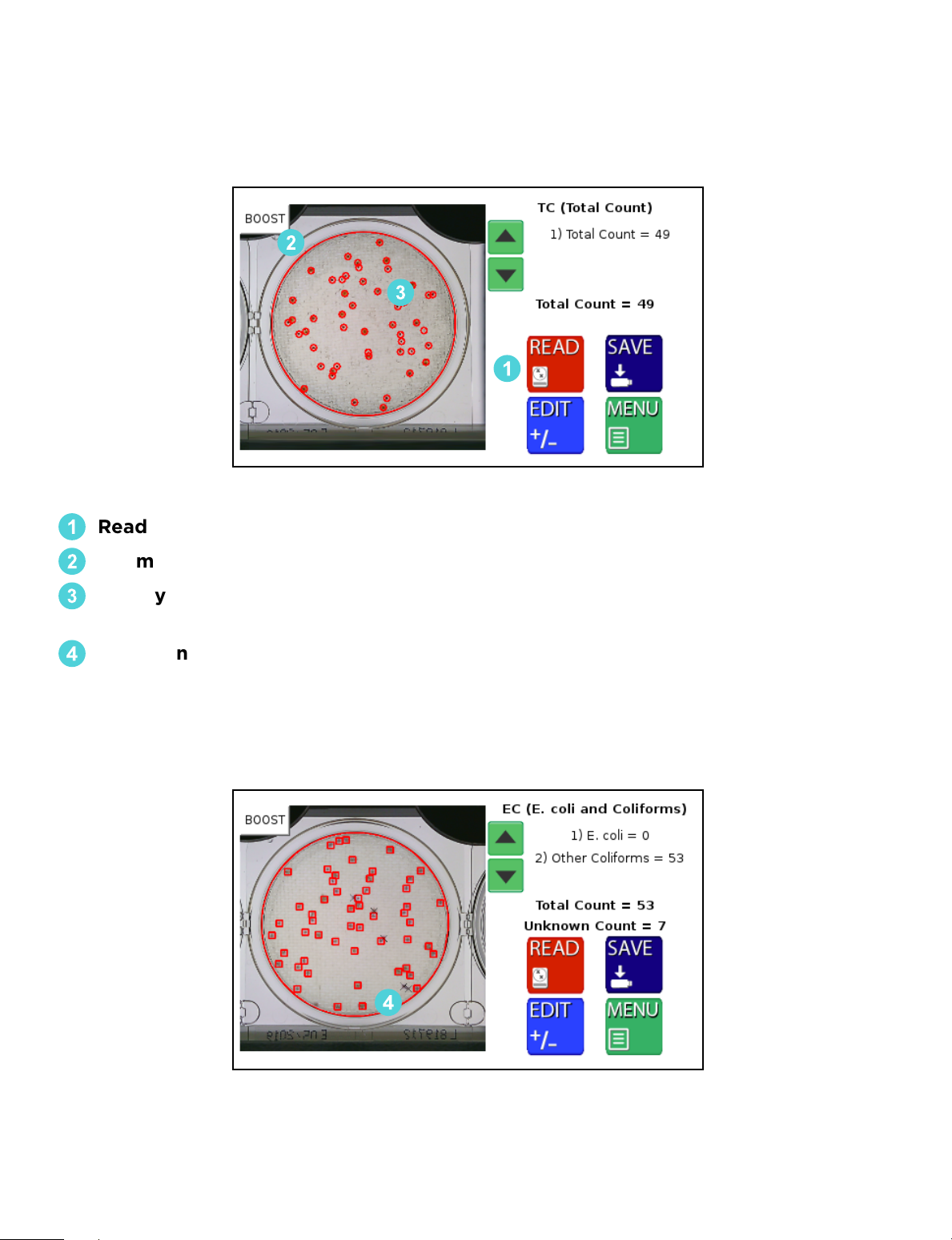
READ SCREEN (Post Reading)
After the image has been read, The Wizard™ CompactDry™ Reader will automatically
direct you to the Post Read Screen.
2
3
1
4
1
Read Initiated – Can be used to re-read the plate if edits are applied.
2
Perimeter Marks – The perimeter of the plate is detected and marked in red.
3
Colony Marks – Colonies are circled in a specific color. The color and design of the
marker can be changed in the Markers Screen (see pg. 13).
4
Unknown Colony Marks – The Unknown Colonies are marked with an “x” by
default and counted separately. The color and design of the marker can be
changed in the Markers Screen. Unknown count is recorded for any debris or
particulate that is on the plate. This function is turned o by default.

10
This feature is for manually adjusting colony counts. For QC and validation purposes,
please use the Advanced Configuration feature (see pg. 15). This feature will not change
how a colony is categorized, it will only change if it is recognized. A more in depth
method is required if the colony is not categorized correctly.
Within the Edit Screen are the following functions:
• Plate designation/colony type check
• Colony count adjustment
• Adjust screen sensitivity
• Boost function
If The Wizard™ CompactDry™ Reader is not detecting all colonies due to overlap or
obscurity, users have three options to adjust their plate count.
32
1
1
First, select the type of colonies that require a count adjustment.
2
Adjust the count with the -/+ buttons. The image will not change but will add or
remove colonies numerically to the selected colony type.
3
Exit back to the read screen with the MENU button. The updated count can now
be saved to the USB or printed with the thermal printer.
Edit Screen
11
Technical Support: 800-266-2222, option 2
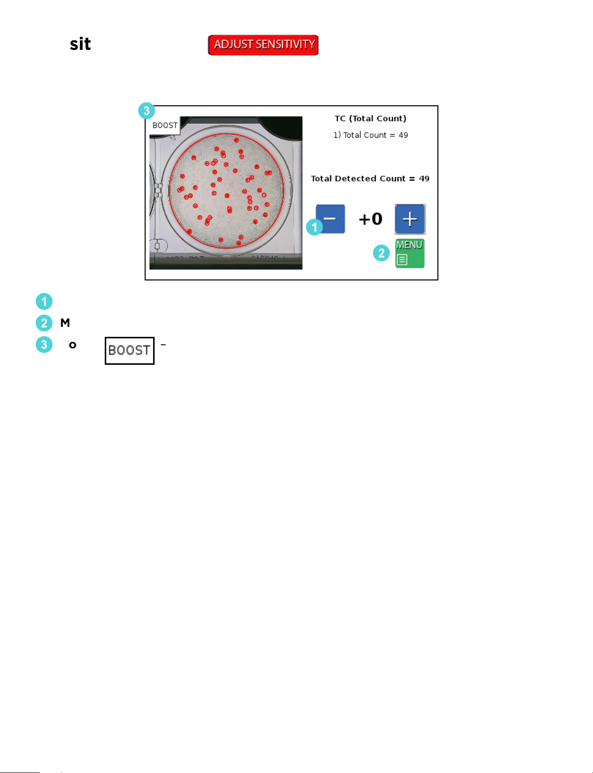
Allows user to manually raise or lower camera sensitivity preferences.
1
- / + Buttons - Adjust the sensitivity up/down to all the colonies.
2
Menu – Press the Menu button to exit to Sensitivity Screen.
3
Boost – Can be calibrated through
Advanced Configuration (see pg. 15).
2
1
3
Sensitivity Screen

12
3 4 52
1
1
Sample ID: Enter the name of the sample or identification number. Optional
Barcode Scanner or USB Keyboard can also be used to input this data.
2
Print: The Print Button will send the data to the USB thermal printer. Sample ID,
colony count data and images of the plate will be printed in black and white.
Based on the configurations setting, the camera will print the raw image and/or the
image with the markers.
3
Save: Plate count data will be saved to a USB drive as a CSV file listed by the
Sample ID. The image of the plate with or without the markers can also be saved to
the USB.
4
Send: Data can be sent to PC, LIMS, or the Hardy Data Receiver Program (HDRP,
see pg. 23) by use of the USB to Ethernet adapter. For established LIMS
(Laboratory Information Management System) integration, users will need to work
with their LIMS provider to integrate the The Wizard™ CompactDry™ Reader into
their software.
5
Exit: This enables the user to exit the keyboard function and return to the
previous screen.
Users have the ability to save their data in dierent ways:
Save Screen
13
Technical Support: 800-266-2222, option 2
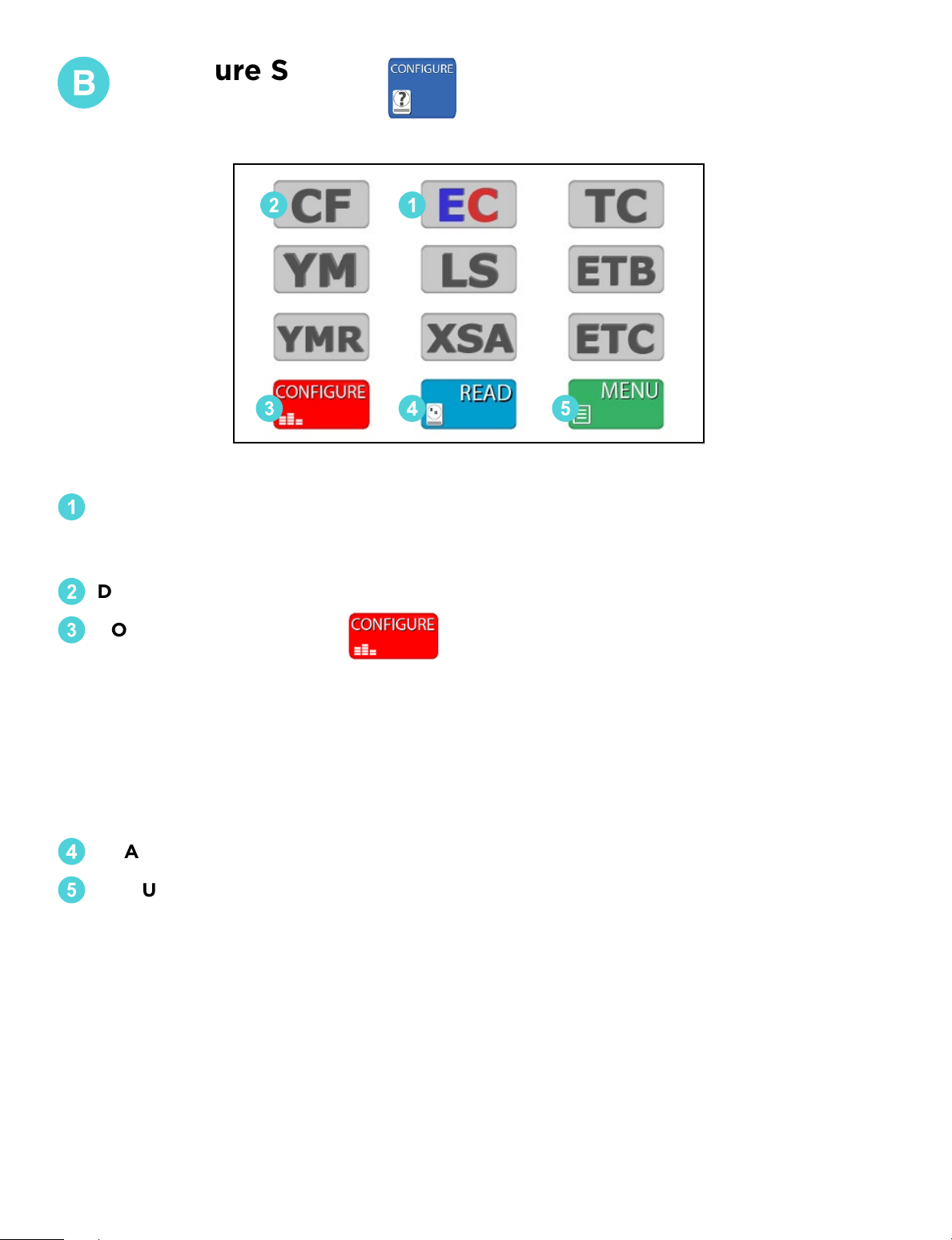
1
SELECTED PLATE – Will appear in color.
Make sure this mode matches the type of CompactDry™ plate the operator is
reading.
2
DESELECTED PLATES – The deselected mode buttons will appear in gray.
3
CONFIGURE SETTINGS –
From the Configure Screen, users can access the following options (see pg. 14):
• Adjust markers
• Save image
• Save markers
• Review plates stored on USB
• Live Imaging
• Advanced Configuration
4
READ - Returns the operator to the Read Screen.
5
MENU – Returns the operator to the Home Screen.
2 1
3 4 5
Configure Screen
14
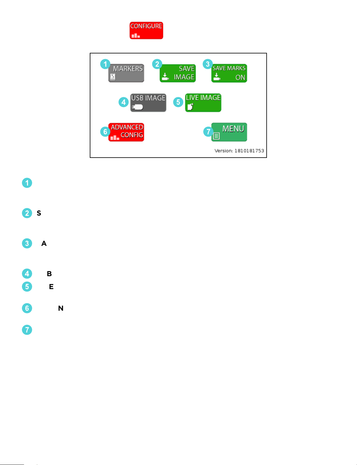
Configure Settings
1
MARKERS: Colony count markers can be customized to plate type. Users have the
option to change the color, shape, weight, and size of the markers for dierent
plate modes.
2
SAVE IMAGE/SAVE DATA ONLY: When this option is highlighted green, saved files
will include an image of the plate with the corresponding plate read data. When
option is in gray, saved files will include only the raw data from the plate read.
3
SAVE MARKERS ON/OFF: When this option highlighted green for ON, saved files
will include two images, one with colony markers and the original raw image of the
plate. When option is gray, saved file will only include raw image of plate.
4
USB IMAGE: Allows users to review and read plates stored on a USB drive.
5
LIVE IMAGE: The default setting for the Wizard reader allows users to read
CompactDry™ plates in real time.
6
ADVANCED CONFIGURATION: This option will be used when calibrating and
validating The Wizard™ CompactDry™ Reader for your sample matrix.
7
MENU: Takes users back to plate mode configuration screen.
2 31
6 7
4 5
15
Technical Support: 800-266-2222, option 2
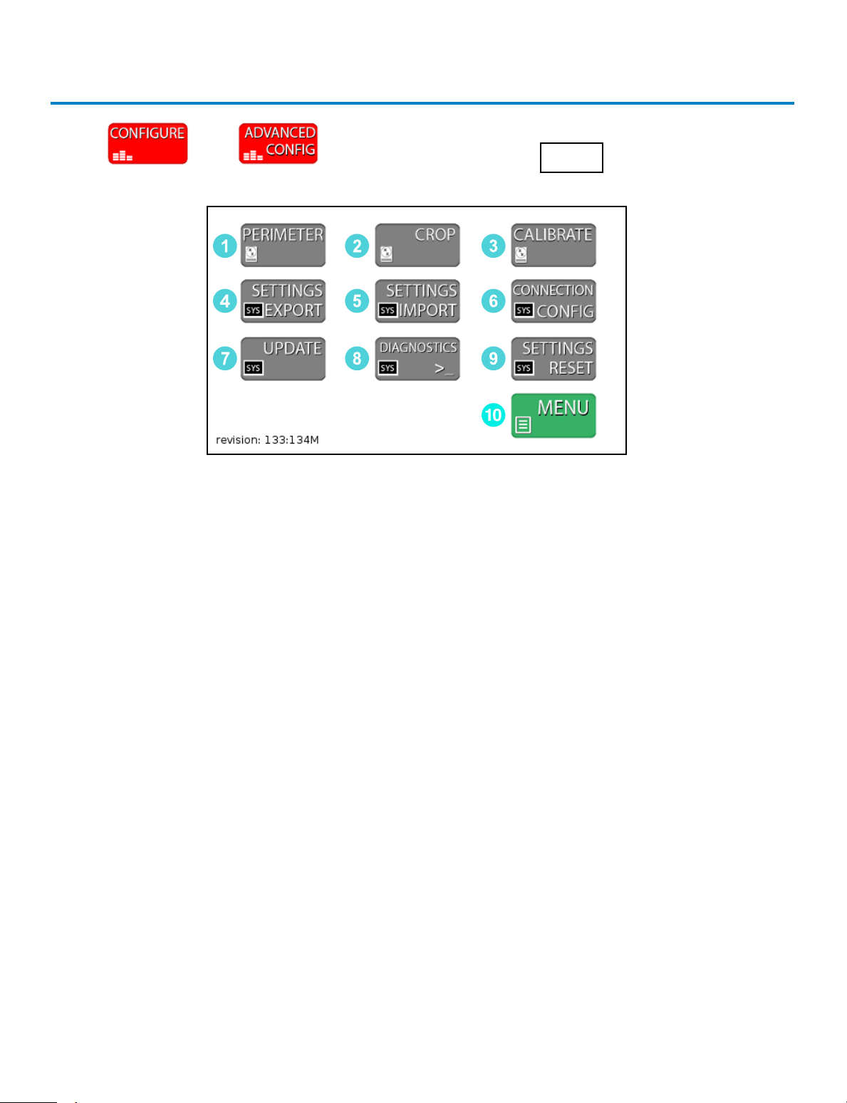
Press then and then enter the code 0855 to enter the
Advanced Configuration screen.
Advanced Configuration
1. PERIMETER - Used to adjust the settings for perimeter detection. This is set during
the factory calibration and should not require adjustment.
2. CROP - Used to adjust the settings for cropping the image. This is set during the
factory calibration and should not require adjustment.
3. CALIBRATE - Enters the CALIBRATE Screen. The CALIBRATE Screen is where the
operator can calibrate the colony detection settings.
4. SETTINGS EXPORT Button – Used to save the Calibration data and system settings
to a USB drive. This can then be used to calibrate an additional unit with the
SETTINGS IMPORT Button.
5. SETTINGS IMPORT Button – Used to save new Calibration data and system settings
to the unit from a USB drive. Settings can be updated easily with the SETTINGS
IMPORT Button
6. CONNECTION CONFIG Button – Used to connect the Thermal Printer and HDRP
or LIMS systems. Once these devices are connected, use this menu to detect and
update the communication settings.
7. UPDATE Button – If the system requires a Firmware Update via USB drive, this
button is used to load the new firmware onto the unit.
8. DIAGNOSTICS Button - For factory use only.
9. SETTINGS RESET Button– Resets to the original factory settings.
10. MENU Button- Returns user to CONFIGURE screen.
2
5
8
3
6
9
1
4
7
10

16
Unit Calibration – Calibrating the Unit
If the system is not detecting colonies it will require calibration. The Wizard detects
colonies based on the contrast between the background color and the colonies. It
then determines if the colony is to be counted by checking it against a color and size
profile. The color is made up of Blue, Green and Red values. There are two methods
to calibrate the unit eectively.
1. Quick Sensitivity Adjustment – If a unit is not detecting colonies, the Sensitivity
can be quickly adjusted in the EDIT screen from the Sensitivity Button. However, it is
recommended to perform a complete calibration as listed in the next steps below.
This method is designed to be a quick work around for “on the fly” sensitivity
adjustments which are normally accomplished with a complete calibration. This
method will not change how a colony is categorized, it will only change if it is
recognized so a more in-depth method is required if the colony is not categorized
correctly. Press to proceed with the adjustment.
2. Configuration Menu Method – The Configuration Menu Method breaks the calibra-
tion into two parts. This is the recommended method for configuring the unit for
quality control prior to use.
a. Sensitivity Screen – Determines what is a colony or detected object based on
contrast sensitivity and size. A boost function is added for enhanced detection of
pinpoint colonies and may be calibrated separately in the same screen.
b. Colony Type Screen – The Colony Type looks at all detected objects and deter-
mines if the object is the colony of interest based on color and size. For modes that
detect multiple types of organisms (YM and EC), multiple Colony Type Screens are
used. A boost function is added for enhanced detection of pinpoint colonies and
may be calibrated separately in the same screen(s).
Summary – If a colony is not detected, the Sensitivity requires adjustment. If a colony
is detected but it is classified incorrectly then the Colony Type Screen will be used to
calibrate the unit. Both adjustments are required to complete a full calibration for
quality control. An added boost function for enhanced sensitivity may be calibrated
during normal calibrations.

17
Technical Support: 800-266-2222, option 2
CALIBRATION SENSITIVITY Screen
The calibration screen can be accessed from the Configuration Menus. The first
calibration screen detects all objects on the plate. A second and sometimes third
filter will determine the type of colony detected. Make sure the unit is in the
correct mode before calibrating. The unit will take a still image of the plate during
calibration to limit distortion of the sample. The unit will not operate as quickly as
in the READ Screen because it is updating and performing calculations. All - / +
buttons in the Calibration screens are dual action. They can be pressed once for
fine adjustment or held down for large adjustments. Every time the calibration
values are changed the unit will update the detection algorithms.
1. The first step of calibrating the unit is to determine the best settings for picking
up all the objects on the plate.
1
Sensitivity and
2
Sensitivity 2 adjustments
determine how sensitive the unit is to detecting objects. The
3
Diameter Min and
4
Diameter Max adjustments are used to filter out items too small or too big,
respectively.
2. The second step of the calibration is calibrating the unit to count the correct
colonies.
3. The third step (if necessary) is calibrating the unit to count a second type of
colony like the YM (Yeast and Mold Mode) or EC (E. coli and Other Coliform Mode).
4. Steps 1-3 may be repeated to calibrate the Boost function which allows for
enhanced sensitivity.
CALIBRATION BUTTON:
2
3
1
4

18
Visualization Tools for the Calibration Sensitivity Screen
There are three tools in this screen that assist in the Sensitivity calibration.
1. A picture of the
5
plate being used for calibration is displayed on the screen. This
screen can also be touched to display the Detail on the colony. Until a colony is
selected, the display will read “click on the image.” After selecting a colony, the
details can be used to adjust the settings. Colony Detail Format:
#Colony Number (Value, Saturation, Hue) Diameter Roundness
2. The MASKED
6
Button toggles the view to a black and white image showing the
objects detected in white. This is very helpful for determining the sensitivity setting.
3. The
7
COLONIES VIEW Button (7) is on by default and it highlights the Colonies in
bright green. This is useful in both SENSITIVITY and COLONY TYPE detection.
6
5
7
Table of contents
Popular Medical Equipment manuals by other brands

intensity
intensity Dual Channel TENS user manual

TREVIDEA
TREVIDEA G3 FERRARI G30056 user manual

Novametrix Medical Systems
Novametrix Medical Systems OXYPLETH 520A user manual

Novartis
Novartis EXELON PATCH Instructions for use

Atos Medical
Atos Medical PROVOX LaryTube Standard manual

Tidal
Tidal InSee Instructions for use


Michigan Instruments
Michigan Instruments LIFE-STAT 1008MII Instructions for use

Stryker
Stryker Power-PRO XT 6500 Operation & maintenance manual

CA.MI
CA.MI O2-easy instruction manual

Invacare
Invacare Carroll CS Series user manual

Stryker
Stryker CastVac 0986-000-000 Instructions for use

Unicare Health
Unicare Health ANSA Instruction & safety manual