Hardy Process Solutions 400 Series Specification sheet

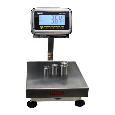
HARDY BENCH SCALES
OPERATION AND INSTALLATION
MANUAL
Hardy Process Solutions
Corporate Headquarters
9440 Carroll Park Drive
San Diego, CA 92121
Phone: (858) 278-2900
FAX: (858) 278-6700
Web-Site: www.hardysolutions.com
Hardy Process Solutions, #0596-0339-01 Rev A2
Copyright 2014-2019 Hardy Process Solutions. All Rights Reserved. Printed in the U.S.A.

CAUTION:
UNPACK WITH CARE
WHEN UNPACKING, DO NOT DISCARD THE PACKING CASE OR ANY
PACKING MATERIAL, UNTIL THE CONTENTS OF THE PACKING CASE
ARE INSPECTED AND CAREFULLY COMPARED WITH THE SHIPPING
DOCUMENTS.
IF ANYTHING IS UNSATISFACTORY, PLEASE NOTIFY HARDY
PROCESS SOLUTIONS IMMEDIATELY BY CALLING, FAXING OR E-
MAILING TO:
Hardy Service Center
Hardy Process Solutions
9440 Carroll Park Drive
San Diego, California 92121
Phone: (800) 821-5831 or (858) 278-2900
FAX:(858) 278-6700
E-mail: [email protected]
Web Address: www.hardysolutions.com
TO RETURN DEFECTIVE OR DAMAGED PRODUCT(S) CALL HARDY
TECHNICAL SUPPORT FOR A HARDY SERVICE TICKET NUMBER
(HST#). YOUR COMPANY NAME, ADDRESS, TELEPHONE NUMBER,
SERIAL NUMBER OF THE UNIT AND A BRIEF DESCRIPTION OF THE
PROBLEM SHOULD BE READY WHEN CALLING. FOR ALL
NON-WARRANTY REPAIRS A PURCHASE ORDER OR CREDIT CARD IS
ALSO REQUIRED.
IN CASE OF DAMAGE DUE TO SHIPPING, NOTIFY THE DELIVERING
CARRIER IMMEDIATELY FOR AN INSPECTION.

Table of Contents
i
Table of Contents
Chapter 1 - Overview 1-1
Introduction 1-1
Description 1-1
The Stainless Steel Top Cover 1-1
Lower Frame Assembly 1-1
Scale Interface 1-1
Hardy Bench Scale Models 1-2
400 Series – HIBS400-xxxx 1-2
300 Series – HIBS300-xxxx 1-2
200 Series – HIBS200-xxxx 1-2
Chapter 2 - Specifications 2-1
Hardy Bench Scale Specifications 2-1
Standard Sizes & Capacities 2-2
Chapter 3 - Installation 3-1
Precautions 3-1
Unpacking 3-1
Adjusting the Mechanical Overload Stops 3-1
Leveling the Scale 3-3
Scale Connections 3-4
Chapter 4 - Calibration 4-1
About Calibration of the Hardy Bench Scale 4-1
C2 Second Generation Calibration 4-1
Test Weight Calibration (Hard Cal) 4-1
Material Substitution 41
Chapter 5- Troubleshooting 5-1
SCOPE 5-1
Problem: 5-1
Scale Does Not Respond When Weight is Applied 5-1
Scale Indication is not linear 51
Scale Reads Backwards 5-1
Scale Reading drifts or is Erratic 5-1
Service and Repair (All Models) 5-2

Chapter 1 - Overview
1-1
CHAPTER 1 - OVERVIEW
Introduction Congratulations on your purchase of a Hardy
Bench Scale. Behind your purchase is over 90
years of quality, reliability and technical innova-
tion.
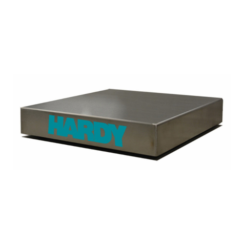
The Hardy Bench Scales are designed for table
top or floor applications requiring high accuracy
and reliability. The covers are all stainless steel
for durability. The bases have no bearings, spirit
levels, or moving parts that can be damaged or
wear out. The active element of the scale is a
precise and accurate strain gauge load sensor.
Description All Hardy Bench Scales come standard in
12”x12”, 18”x18”, and 24”x24” sizes, and range
in capacity from 5lbs – 1,000lbs (2.27kg to 454
kg). Custom sizes and capacities are available
from Hardy upon request.
The basic Hardy Bench Scale consists of three
major components:
1. Stainless Steel Top Cover.
2. Lower Frame Assembly with a load sensor
3. Four Leveling feet.
TheStainlessSteel
Top Cover The top cover is a single piece constructed of
heavy gauge 304 Stainless Steel. The cover pro-
vides a washdown weighing surface and offers
protection to the load sensor and electronics.
Lower Frame
Assembly The lower frame comes equipped with four level-
ing feet, a load sensor, a shock load and corner
overload protection. Depending on the model,
the frame is made of stainless steel or painted
carbon steel.
Scale Interface Directly attach the scale’s 10 foot (3 meter) cable
to any weighing instrument or controller. If inter-
facing with a Hardy Controller, you can take full
advantage of WAVERSAVER®and C2®Elec-

Hardy Bench Scales
1-2
tronic Calibration (C2 is only available with HI
BS400 series).
NOTE: WAVERSAVER®and C2®are registered trade-
marks of Hardy Process Solutions.
Hardy Bench Scale
Models
400 Series –
HIBS400-xxxx The HI BS400 Series is Hardy’s top of the line
industrial bench scale. With all stainless steel
construction and a hermetically sealed, IP68/
IP69K, FM Hazardous approved, stainless steel
Advantage® load cell, the HI BS400 is built for
the heaviest wash down applications and corro-
sive environments. Hardy has built its C2 weight-
free calibration technology into every scale,
delivering the lowest total cost of ownership on
the market. C2 calibration saves time during
commissioning and replacement, removes per-
sonnel from processing areas, and keeps your
process cleaner by eliminating the need for
potentially contaminated test weights.
300 Series –
HIBS300-xxxx The Hardy HI BS300 Series is a Hardy’s lowest
cost stainless steel industrial scale, built to han-
dle light wash down and humid environments.
Each bench scale is equipped with an FM
approved IP67 aluminum load cell, and comes
with NTEP (pending) certifications standard. The
HI BS300 does not come with C2.
200 Series –
HIBS200-xxxx The HI BS200 Series is Hardy’s lowest cost
industrial scale, featuring a painted carbon steel
base and IP67 aluminum load cell made for use
in dry and dusty environments. Each aluminum
load cell is FM approved, and the HI BS200
comes with NTEP (pending) certifications stan-
dard. The HI BS200 does not come with C2.

Chapter 2 - Specifications
2-1
CHAPTER 2 - SPECIFICATIONS
HardyBenchScale
Specifications Platter Construction
• 304 Stainless Steel (all models)
• Size: 12" x 12", 18" x 18" and 24" x 24
(custom sizes are available)
Deck Height
• 12" x 12": 5, 25, 50, 150 lbs: 3.75" to 4.5"
(9.5 to 11.4 cm) adjustable
• 18" x 18": 50, 25, 50, 150 lbs: 3.75" to 4.5"
(9.5 to 11.4 cm) adjustable
• 18 x 18": 300, 500 lbs: 5.5" x 6.5" (14 to 16.5
cm) adjustable
• 24" x 24": all capacities 5.5" x 6.5" (14 to
16.5 cm) adjustable
Capacity Range
5 lbs to 1000 lbs (2.27 to 454 kg)
Rated Output
Overload: 300% R.O.
End loading: 100% R.O.
Corner loading: 100% R.O.
Cable Length
Platform to Instrument - 9 to 10 feet nominal (3
meters) (for longer cable lengths, contact the Factory)
Base Construction
HIBS400 & HIBS300: Stainless Steel
HIBS200: Painted Carbon Steel
Load Sensors
HIBS400:
•C2
® stainless steel, hermetically sealed
IP68/IP69K
• Load Sensor Sensitivity: 2.0mV/V +/- 5%

Hardy Bench Scales
2-2
HIBS300 & HIBS200:
• Aluminum, environmentally potted, IP67
• Load Sensor sensitivity: 2.0 +/- 0.2 mV/V
Resolution
5000 divisions of scale capacity
Accuracy
Combined Error: 0.02%
Temperature
Operating: -10 to +40 degrees celsius
Storage: -20 to +65 degrees celsius
Warranty
Two year limited warranty
Approvals
NTEP (HIBS300 and HIBS200 Only) Pending
FM IS Hazardous Class I, Div 1 Load Cell
Shipping Weight
12" x 12": 38 lbs (17.2 kg)
18" x 18": 59 lbs (26.8 kg)
24" x 24": 104 lbs (47.2 kg)
Standard Sizes &
Capacities

Chapter 3 - Installation
3-1
CHAPTER 3 - INSTALLATION
Precautions Do not store or operate the scale out of its spec-
ified temperature range. (See Temperature
Ranges in Chapter 2)
Do not store other equipment on the scale when
it is not in use or in storage.
Do not allow a build-up of debris on, around or
under the scale.
Do not set the scale in water or allow water to
settle around the scale. Provide Proper drainage.
Do not allow static or other electrical discharges
through the scale.
Do not try to repair the scale. Contact Hardy
ProcessSolutionsTechnicalSupportDepartment
for any and all repairs.
Unpacking Hardy Bench scales are shipped fully assembled
and only require adjustment of the overload
stops and adjustment of the leveling feet. If there
is any damage to the shipping container or to the
scale, save all the packaging material and file a
report with the shipper.
Adjusting the
Mechanical Overload
Stops
There is a bolt in each corner of the frame that is
fully engaged for shipping protection. Each
should be adjusted to allow the load cell to
deflect to its maximum deflection distance, but
no further.

Hardy Bench Scales
3-2
Maximum Deflection at Capacity: HI BS400
HISPB1 Load Sensor (24” x 24”)
HISP6 Load Sensor (12” x 12” and 18” x 18”)
Maximum Deflection at Capacity: HI BS300 &
HI BS200
1250 Load Sensor (24” x 24”)
Capacity Deflection (mm)
50 kg 0.22
100 kg 0.20
250 kg 0.10
500 kg 0.25
Capacity Deflection (mm)
10 kg 0.17
20 kg 0.22
50 kg 0.22
100 kg 0.22
200 kg 0.25
Capacity Deflection (mm)
50 kg <0.40
100 kg <0.40
250 kg <0.40
500 kg <0.40

Chapter 3 - Installation
3-3
1042 Load Sensor (12” x 12” and 18” x 18”)
Leveling the Scale Step 1. The Hardy Bench Scales come with an
integrated leveling indicator at the front
of the base. (See Fig. 3-1). Remove
the top cover and locate the indicator
at the center of the front of the scale
base.
FIG. 3-1 LEVELING INDICATOR
Capacity Deflection (mm)
10 kg <0.40
20 kg <0.40
50 kg <0.40
100 kg <0.40
200 kg <0.40

Hardy Bench Scales
3-4
Step 2. To level the platform, turn the leveling
feet clockwise to lower the scale cor-
ner, or counter clockwise to raise it
until you show a level reading by cen-
tering the bubble in the center of the
indicator.
FIG. 3-2 LEVELING FEET
Scale Connections To connect the scale, you must first remove the
cover, unroll the cable and run the cable through
the hole in the back of the unit. Replace the
cover.
Leveling
Foot
4 Places

Chapter 3 - Installation
3-5
FIG. 3-3 RUNNING CABLE THROUGH HOLE IN BACK
(12”X12” OR 18” X18” INCH SCALE)
FIG. 3-4 HOLE FOR THE CABLE IS AT THE BACK
OF THE INSIDE OF A 24” X 24” SCALE

Hardy Bench Scales
3-6
Make sure the cable is not pinched and is clear
of the feet. The Bench Scale requires a recom-
mended DC or AC excitation voltage of 5 volts
with a maximum of 15 volts. Wire the Scale cable
to an instrument or indicator following the color
code label found on the cable.
For HI BS200 and HI BS300 Scale Models:
+ Excitation Green
- Excitation Black
+ Sense Blue
- Sense Brown
+ Signal Red
- Signal White
Shield Bare
For HI BS400 Scale Models with C2 Electronic
Calibration:
+ Excitation Red
- Excitation Black
+ Signal Green
- Signal White
+ C2 Gray
- C2 Violet
Shield Yellow or Bare
WARNING USE CAUTION WHEN WIRING. MAKE SURE
TO DISCONNECT ALL POWER TO THE
SCALE. FAILURE TO REMOVE POWER CAN
RESULT IN SCALE OR INSTRUMENT DAM-
AGE, DEGRADATION OF PERFORMANCE OR
PERSONAL INJURY
NOTE: Hardy Process Solutions provides drawings you
may download on the Hardy Bench Scales page
under the Docs & Programs tab. Drawings are
provided for each of the Hardy Bench Scale
models in .dxf, dwg, .pdf, and 3D formats. These
drawings include the wiring configurations.

Chapter 3 - Installation
3-7
FIG. 3-5 EXPLODED VIEW OF 12” X 12” OR
18” X 18” SCALE SHOWING SELECTED PARTS

Hardy Bench Scales
3-8
FIG. 3-6 EXPLODED VIEW OF 24” X 24” SCALE
SHOWING SELECTED PARTS

Chapter 4 - Calibration
4-1
CHAPTER 4 - CALIBRATION
About Calibration of
the Hardy Bench Scale The Hardy Bench Scales come calibrated from
the factory. Make sure the scale is correctly wired
to the weighing instrument or indicator. Refer to
the weighing instrument or indicator manual for
calibration instructions.
C2 Second Generation
Calibration C2 electronically calibrates a scale system with-
out the need for test weights. If you are using a
Hardy Process Solutions Weight Controller,
Weight Processor, Indicator or Weigh Module, all
that’srequired is to enter a reference point. Refer
to the instrument or module manual for calibra-
tion instructions using C2/
NOTE: Hardy C2 calibration is only available in the
HI BS400 model as a standard feature.
Test Weight
Calibration (Hard Cal) This is the traditional means of calibration requir-
ing certified class F test weights equal to a mini-
mum of 80% of the rated scale capacity.
Three weights between 10% and 100% of the
scale capacity should be available to check the
mid-range. Several low capacity weights equiva-
lent to one or two instrument divisions are neces-
sary to check the system sensitivity.
NOTE: Traditional Calibration is required for the HI
BS200 and HI BS300 models because they do
not come with C2 load cells.
Material Substitution When certified test weights are not available you
can use an accurately weighed material to cali-
brate the system. In this method, a material is
weighed on a secondary, calibrated scale and
delivered to the site of the scale to be calibrated.
The secondary calibrated scale should be of the
same accuracy or greater and have a capacity
approximately equal to the scale being cali-
brated.

Chapter 5- Troubleshooting
5-1
CHAPTER 5- TROUBLESHOOTING
SCOPE All the information in Chapter 5 pertains to the
troubleshooting and resolution of operating prob-
lems that may occur. All maintenance personnel
and users should be familiar with both Chapters
3 and 4 before attempting to troubleshoot prob-
lems with the Scale.
Problem:
Scale Does Not
Respond When
Weight is Applied
Step 1. Make sure the scale is wired correctly
to the instrument or network and there
are no breaks in the wiring.
Step 2. Check to see if there is packing mate-
rial or debris wedged under or against
the scale.
Step 3. Make sure the corner mechanical
overload stops are not engaged with
the platform. Lower as necessary.
Scale Indication is
not linear Step 1. Check the instrument for proper cali-
bration.
Step 2. Check to see if there is packing mate-
rial or debris wedged under or on the
side of the scale.
Step 3. Make sure the corner mechanical
overload stops are not engaged with
the platform. Lower as necessary.
Step 4. Make sure all electrical connections
are tight with no corrosion and that
there has not been an ingress of mois-
ture to the system.
Scale Reads
Backwards Step 1. Check for correct wiring to the instru-
ment. The +- signal or excitation wires
may be reversed.
Scale Reading
drifts or is Erratic Step 1. Make sure all electrical connections
are tight with no corrosion and that
there has not been an ingress of mois-
ture to the system.

Hardy Bench Scales
5-2
Step 2. Make sure the corner mechanical
overload stops are not engaged with
the platform. Lower as necessary.
Step 3. Verify that the instrument or network is
operating properly.
Step 4. Make sure there are no high voltage
wires close to the scale.
Step 5. Check that the scale and instrument
are properly grounded.
Step 6. If high static electricity is present a
ground strap should be added from the
top cover to the chassis and to earth
ground.
Service and Repair (All
Models) For Service and Repairs, contact your local
Hardy Representative.
Before returning any product to Hardy Process
Solutions, please contact the Hardy Service Cen-
ter for a return authorization number. Please
have the scale model number and a serial num-
ber and a brief description of the problem ready
when you call.
Technical Support
Hardy Process Solutions
9440 Carroll Park Drive
San Diego, California 92121
US Customers Only: 800-821-5831
Outside the US: 858-278-2900
This manual suits for next models
5
Table of contents
Other Hardy Process Solutions Scale manuals

Hardy Process Solutions
Hardy Process Solutions Enviro Series User manual

Hardy Process Solutions
Hardy Process Solutions HIFS-3030-01-PS-T Specification sheet

Hardy Process Solutions
Hardy Process Solutions C Series Specification sheet

Hardy Process Solutions
Hardy Process Solutions HI 1769-WS Specification sheet

Hardy Process Solutions
Hardy Process Solutions BSX Series User manual
Hardy Process Solutions
Hardy Process Solutions BW Series User manual