Hargrove OBLO19N1T Operating instructions

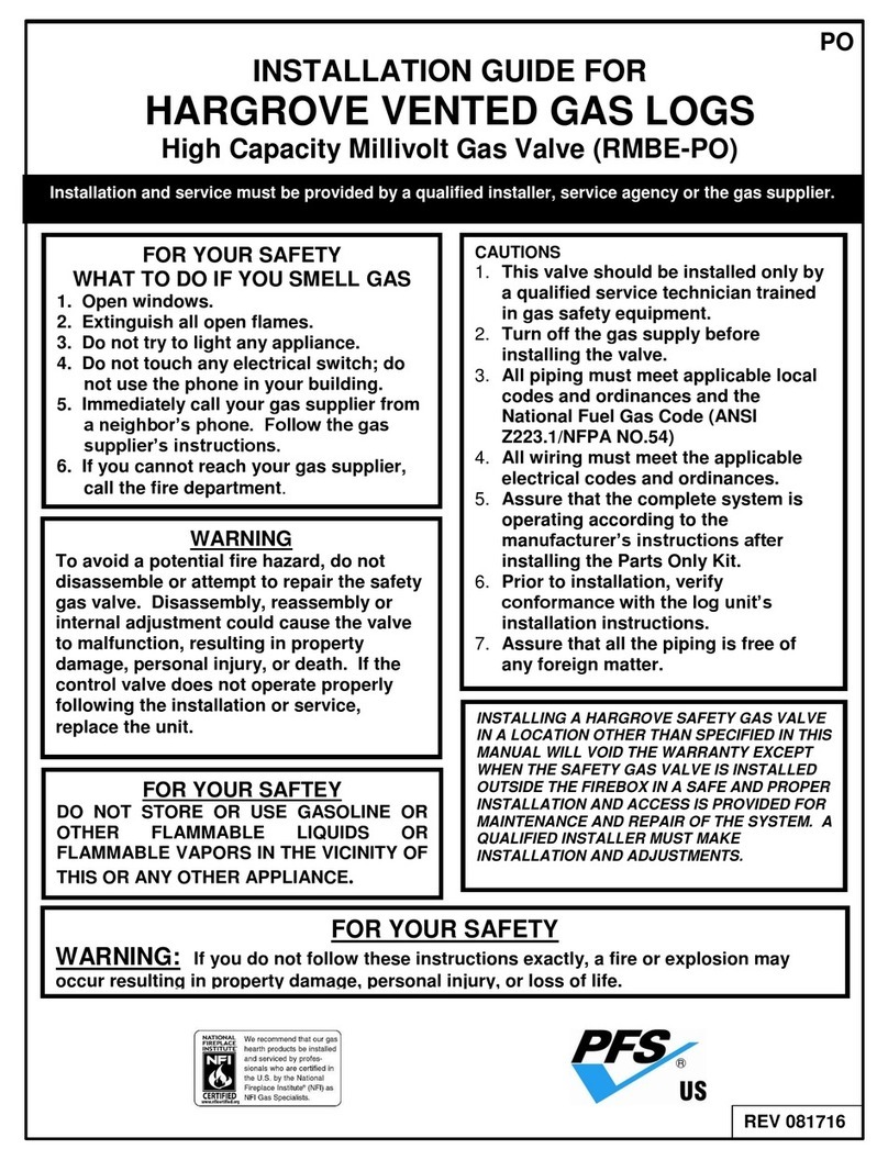
Installation and service must be provided by a qualified installer, service agency or the gas supplier.
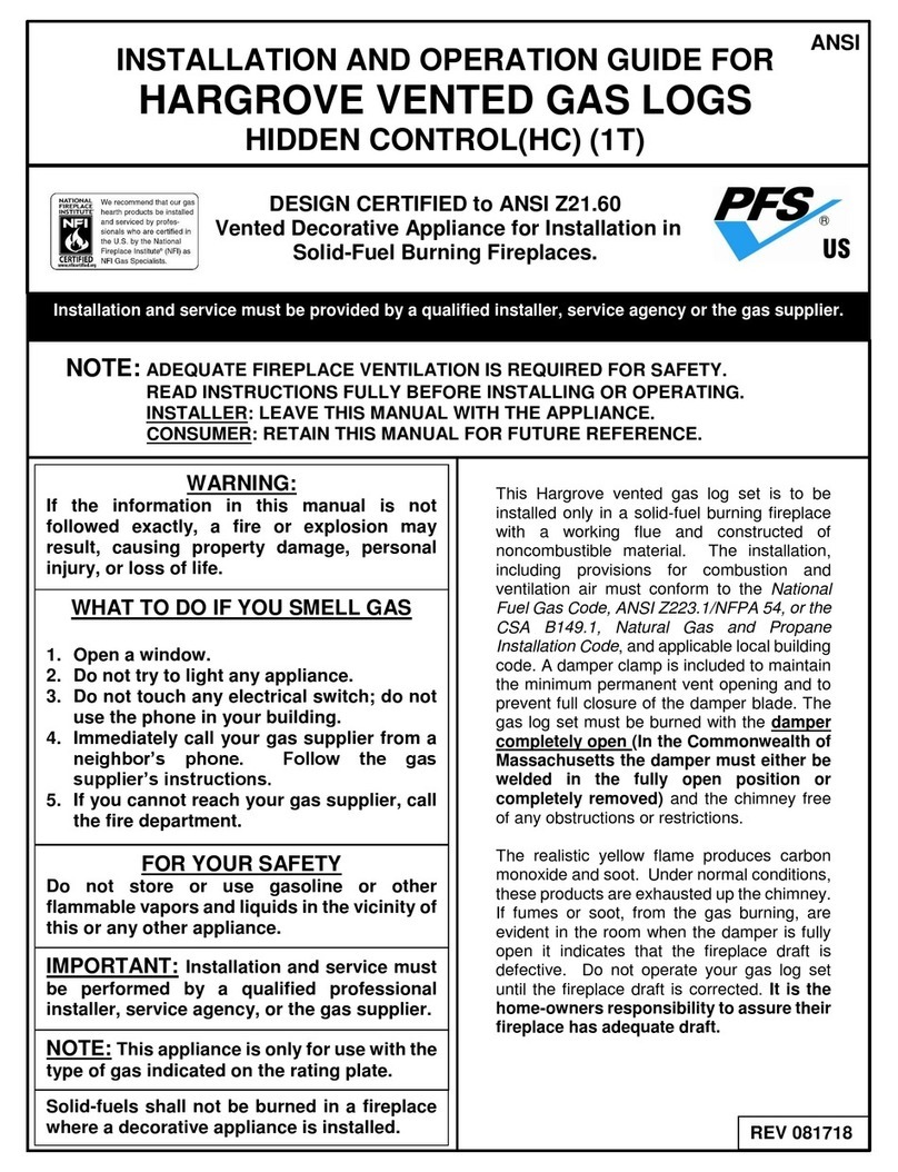
INSTALLATION AND OPERATION GUIDE FOR
HARGROVE VENTED GAS LOGS
OLDE WORLD BASKET
DESIGN CERTIFIED to ANSI Z21.60/CGA 2.26
Vented Decorative Appliance for Installation in
Solid-Fuel Burning Fireplaces.
NOTE: ADEQUATE FIREPLACE VENTILATION IS REQUIRED FOR SAFETY.
READ INSTRUCTIONS FULLY BEFORE INSTALLING OR OPERATING.
INSTALLER: LEAVE THIS MANUAL WITH THE APPLIANCE.
CONSUMER: RETAIN THIS MANUAL FOR FUTURE REFERENCE.
ANSI
FOR YOUR SAFETY
Do not store or use gasoline or other
flammable vapors and liquids in the vicinity of
this or any other appliance.
WARNING:
If the information in this manual is not
followed exactly, a fire or explosion may
result, causing property damage, personal
injury, or loss of life.
WHAT TO DO IF YOU SMELL GAS
1. Open a window.
2. Do not try to light any appliance.
3. Do not touch any electrical switch; do not
use the phone in your building.
4. Immediately call your gas supplier from a
neighbor’s phone. Follow the gas
supplier’s instructions.
5. If you cannot reach your gas supplier, call
the fire department.
IMPORTANT: Installation and service must
be performed by a qualified professional
installer, service agency, or the gas supplier.
NOTE: This appliance is only for use with the
type of gas indicated on the rating plate.
Solid-fuels shall not be burned in a fireplace
where a decorative appliance is installed.
Olde World Basket sets are available with
either a gas log or coal look. The gas logs are
made with refractory materials while the coals
are made of ceramic fiber. Each log is hand-
finished to assure the most realistic, detailed
log available. The coal is designed to achieve
the glowing characteristics of real coal. The
burner system is designed to burn like wood,
with a smoky flame. For this reason, the set
must be burned only in a fully vented, non-
combustible fireplace with the damper
completely open (In the Commonwealth of
Massachusetts the damper must be either
permanently welded in the fully open
position or completely removed) and the
chimney free of any obstructions or
restrictions. The fireplace must be designed
and approved to burn wood.
The realistic yellow flame produces carbon
monoxide and soot. Under normal conditions,
these products are exhausted up the chimney.
If fumes or soot, from the gas burning, are
evident in the room when the damper is fully
open it indicates that the fireplace draft is
defective. Do not operate your gas log set
until the fireplace draft is corrected. It is the
home-owners responsibility to assure their
fireplace has adequate draft.
REV 080416

WARNING: This appliance assembly contains burner orifices specifically for the input
gas and Btu rating. Modifying or failure to use the factory orifice may cause property
damage, personal injury or loss of life.
1. It is recommended that adults be present when this gas appliance is operating. It is recommended that this unit
is not left burning when unattended or while anyone is sleeping.
2. Do not use a natural gas set for propane or a propane set for natural gas. If the gas type is not correct. DO NOT
INSTALL. Contact your dealer for immediate assistance.
3. There are many different local codes for gas fire logs. The installation and the provision for combustion and
ventilation air must conform to local codes and, or in the absence of local codes, with the National Fuel Gas
Code ANSI Z223.1 –(most current revision).
4. Gas log sets must be installed by personnel qualified for installing gas appliances.
5. This appliance must be installed only in a solid-fuel burning fireplace with a working flue and constructed of
noncombustible materials. Solid fuels are not to be burned in a fireplace where a decorative appliance has
been installed.
6. A permanent free opening must be provided by either the fireplace chimney or chimney damper to vent flue
gasses. Any chimney damper must be fixed in a manner, which will maintain the permanent free opening at all
times. Use Table II to determine the minimum permanent free opening based on chimney height and the
appliance Btu input rating. Refer to the Damper Stop section for additional directions.
7. The minimum free opening is based only on two factors; chimney height and Btu input rating. Many other
factors affect the fireplace drafting. It is the homeowner’s responsibility to assure their fireplace has adequate
draft. If fumes or soot from the gas burning are evident in the room when the damper is fully open, it indicates
that the fireplace draft is defective. Do not operate your gas log set until the fireplace draft is corrected. Consult
your fireplace specialist.
8. A fireplace screen must be in place when the appliance is operating and, unless other provisions for combustion
air are provided, the screen shall have an opening(s) for introduction of combustion air.
9. When glass fireplace doors are used, always operate gas log set with the doors fully open to allow for proper
combustion air and to keep control valves from overheating.
10. The minimum inlet supply pressure for the purpose of input adjustment is 5.0 inches (natural gas) 11 inches
(propane gas) in water column. The maximum inlet supply pressure is 10.5 inches (natural gas) 13 inches
(propane gas) in water column.
11. The appliance and its individual shut-off valve must be disconnected from the gas supply piping system during
any pressure testing of that system at test pressures in excess of 1/2 psig (3.5kPa). The appliance must be
isolated from the gas supply piping system by closing its individual manual valve during pressure testing equal
to or less than 1/2 psig (3.5kPa).
12. The fireplace chimney or venting system should be examined annually and cleaned as required by a qualified
agency.
13. After burning for several hours the logs become fragile and should not be handled. Knocking or rubbing logs
can cause concrete to crumble and is not covered under the warranty.
14. To clean the logs, use a soft dry paintbrush for periodic dusting of the gas fire logs.
15. To clean the burner, shut off the gas supply, remove the burner pan media, and vacuum the burner ports. After
cleaning, replace burner pan media and light the pilot according to the lighting instructions.
IMPORTANT PRE-INSTALLATION AND FIREPLACE SAFETY INFORMATION
2

Each Olde World Basket set requires a minimum 16-inch front opening height and minimum 10-
inch depth. Table I below indicates the other critical dimensions.
TABLE II
FACTORY BUILT FIREPLACES
Free opening area of chimney damper for venting combustion products from decorative
appliances for Installation in solid fuel burning fireplaces
TABLE III
MASONRY BUILT FIREPLACES
Free opening area of chimney damper for venting combustion products from decorative
appliances for installation in vented fireplaces.
SPECIFICATIONS AND DIMENSIONS
3
TABLE I
Minimum Front Minimum Minimum
Set Size Opening Width Depth Height
19” 22” 10” 16”
Factory
Built
Appliance Input Rate (kBTU/hr)
20
30
34
40
Chimney
Height* (ft)
Minimum Opening** (sq. in.). (Minimum Diameter (in.))
10
11.3
16.6
18.8 (5”)
22.1
15
8.6
12.6
14.5 (5”)
17.3
20
7.5
10.8
12.3 (4”)
14.5
25
6.6
9.6
10.8 (4”)
12.6
30
6.2
9.1
10.0 (4”)
11.3
35
5.7
8
9.1 (3.5”)
10.8
40
5.3
7.5
8.6 (3.5”)
10.2
* Height is from hearth to top of chimney and the minimum height is 10 ft
** Chart shows minimum opening (sq. in.) for a given height and input rate
Masonry
Built
Appliance Input Rate (kBTU/hr)
20
30
34
40
Chimney
Height* (ft)
Minimum Opening** (sq. in.)
6
17.6
25.7
28.9
33.8
8
16.5
23.7
26.7
31.2
10
15.1
21.7
24.5
28.7
15
14.1
19.9
22.4
26.1
20
12.9
18.5
20.6
23.7
30
12.2
16.9
18.8
21.6
* Height is from hearth to top of chimney and the minimum height is 6 ft
** Chart shows minimum opening (sq. in.) for a given height and input rate

CAUTION
THE DAMPER MUST BE FULLY OPEN WHEN
OPERATING THE GAS LOGS!
FIREPLACE AND CHIMNEY
Fireplace is approved for solid-fuel burning and made of non-combustible materials.
Operational damper with a chimney free of any obstruction or restriction.
Fireplace has proper draft to accommodate decorative appliance.
Fireplace is free from debris or ash.
Fireplace is free of obstruction such as log grate, log lighter, etc.; that would prohibit
the installation of the log set.
If the floor is recessed or glass doors are installed on the fireplace, the appliance may
need to be elevated to ensure proper air flow.
Consult table to determine if the set isproperly sized for the installation inthe fireplace.
GAS LINE
Ensure gas line is in safe condition and that it is adequate for the installation.
Check gas line sizing to ensure it is properly sized for the appliance.
For ease of installation gas line should be located on the right side of the fireplace
when possible.
Turn the gas supply line off and you are ready to begin burner installation.
Attach the damper stop clamp to the fireplace damper blade. Position the clamp to prevent full closure
of the fireplace damper blade.
If the damper stop provided does not fit, the installer shall install a permanent damper stop that will keep
the damper open to a minimum opening as determined on page 3 Table II of the instructions.
4
DAMPER STOP INSTALLATION
IMPORTANT: In the Commonwealth of Massachusetts the damper must be
either permanently welded in the fully open position or completely removed.
PRE-INSTALLATION CHECKLIST
Prefab Fireplace
Masonry Fireplace

*Photos not to scale
BURNER PARTS LIST
5
NOTE: Replacement parts can be ordered from your local Hargrove dealer.
ITEM PART NUMBER DESCRIPTION
A OB-14 Burner
B OG19 Basket
C SKC-C Safety Pilot Valve
D RSTPB-18 Pilot Assembly (NG)
RSTPB-18LP Pilot Assembly (LP)
E 68-0506 3/8” Male X 5/16” Compression
F 68-0506 3/8” Female X 5/16” Compression
G SE-6 3/8” Black Elbow
H N-6-2.5 3/8” X 1 ½” Pipe Nipple
I REG 4 Regulator (NG)
REG 10 Regulator (LP)
J 48-6 3/8” Brass Union
K. AM 3/8 X 3/8 #33 3/8” Air Mixer (NG)
AM 3/8 X 3/8 #51 3/8” Air Mixer (LP)
L. AM-N 3/8 3/8” Air Mixer Nut (NG only)
M. FC-16 Flex Connector
N. OWB-TUBE-R 5/16” Tubing
O. OB-VB Valve Bracket
P. 10-32X1/4” Pilot Screws
Q. 10-1/2” Screws
R. 10-1 ½” Valve Mounting Screws
A
C
D
E
F
G
H
I
J
K
L
M
N
O
P
Q
Q
R
B

BASKET POSITION
BURNER POSITION
GAS CONNECTION
Check that the gas is turned off. Any
remote kits should be installed on the
burner at this point, refer to instructions
with kit for that installation.
The gas supply line should be ½”
inside diameter (ID) up to 30 feet and
¾” for longer distance.
Use the non-whistling flex connector
provided in the accessory kit to
connect the gas supply to the burner
kit. Check to make sure the burner is
in the correct position.
Turn the gas supply on and check
connection for leaks using a soapy
solution.
NOTE- at this point install and
program any remote kits, refer to
the instructions provided with
those kits for installation.
Connect to gas
IMPORTANT: The minimum inlet supply pressure for
the purpose of input adjustment is 5.0 inches (natural
gas) 11 inches (propane gas) in water column. The
maximum inlet supply pressure is 10.5 inches (natural
gas) 13 inches (propane gas) in water column.
BASKET PLACEMENT
Refer to the Basket Assembly Instructions
to put the basket together.
Place the Decorative Basket over the
burner leaving a uniform distance between
the two.
The basket should be placed so that the
burner is centered inside of the basket with
the Valve Cover Plate facing the front.
BURNER POSITIONING
Check that the gas is turned off.
Center the burner on the fireplace floor.
The burner should be located under the
flue opening.
Proceed with the gas connection.
NOTE- if the floor is recessed or
glass doors are installed, burner
must be elevated with firebrick or
equivalent to ensure proper air flow
over valve systems.
6
Burner
Basket
Valve Cover
Plate

Thermocouple
Pilot Flame
RSTPB-18
SKC-C
Pilot Adjustment Screw
Vermiculite
Glowing Embers
7
LIGHTING THE PILOT
Read the lighting instruction plate
attached to the gas valve or located at
the end of these instructions.
Push in gas control knob slightly and turn
clockwise until the knob will not turn any
longer. This is the “OFF” position. The
word off should be at the 12 o’clock
position on the control knob.
Slightly push in on pilot knob and turn
valve to the “PILOT” position. Push the
knob in all the way and hold in.
Immediately light the pilot. (The pilot is
located on the back right corner of the
burner pan) Continue to hold the knob for
at least 30 seconds after the pilot is lit.
Release the knob and the pilot should
remain lit.
Turn the burner to the “ON”, the pilot
flame should ignite the main burner within
4 seconds.
Carefully check the connections for
leaks using a soapy solution.
NOTE- if the pilot will not stay lit after
several tries turn the control off and
call a technician.
IMPORTANT: These controls are factory preset and
will not normally require additional adjustment of the
pilot flame. If field adjustment of the pilot flame is
required, adjust using the pilot adjustment screw. The
90 degree pilot should produce 2 flames about 1-1 ½”
in 2 directions. One flame should come towards the
front of the firebox to ignite the burner and the other,
wrapping around the thermocouple to ensure proper
valve operation.
BURNER MEDIA
Fill the burner pan with vermiculite. The
media level should fill the burner entirely.
Under filling will cause uneven flame.
Glowing Embers (Rockwool) are placed
over the media. For best results pinch off
pieces of the rockwool the size of a dime
and feather it out
Test fire the burner once again for
flame distribution, media can be
altered to achieve desired flame
appearance.

LOG INSTALLATION
8
1. Identify the logs using the pictures on this page.
2. Take the 1110 and 0602 and put them into the basket resting on the front of the basket
as is shown above. (Fig 1.)
3. Place the 104 with the forks down and leaning on the 1110 as is shown above.
(Fig 2.)
4. Take the 112 and 2512 and place them with the 2512 resting on the 602 and the
112 resting on the 1110 as shown below (Fig 4.)
Fig 1
Fig 2
Fig 3

FOR YOUR SAFETY: Do not use this appliance if any part has been underwater.
Immediately call a qualified service technician to inspect the appliance and to replace any
part of the system or gas control, which has been underwater
VOLCANIC CINDER PLACEMENT
The black volcanic cinders are used to cover the fireplace floor, fittings and tubing around the
burner system. Although not functional, the back cinders act as a picture frame to show off the
glowing embers and yellow flame.
9
COAL INSTALLATION
1. Install the short and long base pieces on the tabs with two coal pieces between them.
(Fig 1)
2. Install 6 coal pieces on top of the base pieces. (Fig 2)
Fig 1
3. Install the remaining coal pieces on top. (Fig 3)
Fig 2
Fig 3

FOR YOUR SAFETY READ BEFORE LIGHTING
WARNING: If you do not follow these instructions exactly, a fire or explosion may result
causing property damage, personal injury or loss of life.
A. This appliance has a pilot, which must be
lit by hand. When lighting the pilot, follow
these instructions exactly.
B. BEFORE LIGHTING smell all around the
appliance area for gas. Be sure to smell
next to the floor because some gas is
heavier than air and will settle on the
floor.
WHAT TO DO IF YOU SMELL GAS:
1. Do not try to light any appliance.
2. Do not touch any electric switch; do not
use any phone in your building.
3. Immediately call your gas supplier from a
neighbor’s phone. Follow the gas
supplier’s instructions.
4. If you cannot reach your gas supplier, call
the fire department.
C. Use only your hand to push in or
turn the gas control knob. Never
use tools. If the knob will not push
in or turn by hand, do not try to
repair it. Call a qualified service
technician.
D. Do not use this appliance if any
part has been under water.
Immediately call a qualified service
technician to inspect the appliance
and to replace any part of the
control system and any gas
control, which has been
underwater.
LIGHTING INSTRUCTIONS
GAS OUTLET
GAS INLET
Pilot Adjustment
Screw
Pilot Gas
Supply
4. Find pilot –follow metal tube from the gas control
behind the burner pan.
Pilot Burner
Thermocouple
1. STOP! Read the safety information above on
this label.
2. Push in gas control knob slightly and turn
clockwise to “OFF”.
CONTROL
KNOB
NOTE: Knob cannot be turned from “PILOT” to
“OFF” unless knob is pushed in slightly. Do not
force.
3. Wait five (5) minutes to clear out any gas. If you
then smell gas, STOP! Follow “B” in the safety
information above. If you don’t smell gas, go to
next step.
9
5. Turn knob on gas control counter-clockwise to
“PILOT”.
6. Push in control knob all the way and hold in.
Immediately light the pilot with a match. Continue
to hold the control knob in for about one minute
after the pilot is lit. Release knob and it will pop
back up. Pilot should remain lit. If it goes out,
repeat steps 3 –7.
* If knob does not pop up when released, stop and
immediately call your service technician or gas
supplier.
* If the pilot will not stay lit after several tries, turn the
gas control knob to “OFF” and call your service
technician or gas supplier.
7. Turn gas control knob counterclockwise to “0N”.
LIGHTING INSTRUCTIONS
1. Turn knob clockwise from “ON” position to the “PILOT” position. Push in the gas control knob slightly
and turn clockwise to “OFF”. Do not force knob.
10

LIMITED WARRANTY
Refractory Logs
Hargrove gas logs carry a limited lifetime warranty against any manufactured defect or breakage. This warranty does not cover
breakage caused by excessive handling once installed and fired. Contact Customer Service for warranty claim details.
Burner & Grate
If the burner or grate fails due to deterioration within five (5) years of the verified purchase date, contact Customer Service for
warranty claim details.
Valves, Remote Controls, & Switching Devices
All valves, remote controls and switching devices are warranted against manufacturing defects which appear within two (2) years
of the verified purchase date. Warranty does not cover products that have been damaged by misuse from overheating. Before
any product is returned a Return Goods Authorization number (RGA) must be issued by the Customer Service Department. All
returns must be accompanied by an explanation of the problem and all necessary parts.
All Other Parts
If any assembled part should fail to operate or be found defective which appear within two years of the verified purchase date,
contact Customer Service for warranty claim details
Buyer shall notify Customer Service of any defect covered by this warranty no later than thirty (30) days after defect is discovered.
Failure to provide notice within thirty (30) days shall void the limited warranty.
WHAT IS NOT COVERED
1. Removal and reinstallation costs.
2. Labor costs for replacement or repairs.
3. Transportation or shipping cost.
4. The cost of a service call to diagnose trouble.
5. Painted Surfaces.
6. Damage or defect caused by improper installation, accident, misuse, abuse, alteration, or authorized service technician.
7. Replacement of burner or combustion chamber resulting from improper storage of the appliance.
LIMITATIONS AND EXCLUSIONS
1. No one has authority to add to or vary this limited warranty, or to create for Hargrove Manufacturing Corporation any other
obligation or liability in connection with this appliance.
2. Any implied warranty applicable to this appliance is limited in duration to the same period of time as this written warranty.
Some states do not allow limitations on how long an implied warranty lasts, so the above limitations may not apply to you.
3. HARGROVE MANUFACTURING CORPORATION WILL NOT BE LIABLE FOR INCIDENTAL, CONSEQUENTIAL, SPECIAL
OR CONTINGENT DAMAGES YOU MIGHT SUFFER AS A RESULT OF A CLAIM UNDER THIS WRITTEN WARRANTY OR
ANY IMPLIED WARRANTY. Some states do not allow the exclusion or limitation of incidental or consequential damages, so the
above limitations or exclusion may not apply to you.
4. This warranty applies only to the original purchaser and may not be transferred or assigned.
5. If you cannot verity the purchase date of the appliance, the warranty period will begin on the date of which the appliance was
manufactured.
6. Replacement or repair parts are warranted for the remaining period of the original part warranty. Warranty parts must be
obtained through authorized dealers of this product who will provide original factory replacement parts. Failure to use original
factory replacement parts voids this warranty.
7. The maximum liability of Hargrove Mfg Corp. in connection with this limited warranty shall not in any case exceed the contract
price paid for the product claimed to be defective or unsuitable.
8. Purchaser or user agrees to hold Hargrove Mfg Corp. harmless from any and all claims by the buyer as a result of injury or
damage to an ultimate user or other person caused by the product sold herein by the seller to the buyer, whether the injury or
damage results from the assembly, installation, operation, shipment, storage, or manufacture of this product. Hargrove Mfg Corp.
makes no warranties, expressed or implied, other than those expressly stated herein.
YOUR DUTIES
This appliance must be installed by a qualified installer, operated and maintained in accordance with all applicable codes and the
instructions furnished with the appliance. You must provide a receipt verifying the purchase date of the appliance when making a
warranty claim with the dealer from which the appliance was purchased.
This warranty gives you specific legal rights, and you may also have other rights, which vary from state to state.
CONTACT INFO: Hargrove Gas Logs
207 Wellston Park Rd. –Sand Springs, OK 74063
Toll Free –(800)725-4166
www.hargrovegaslogs.com
Customer Service hours: 8:00am to 4:00pm CST
11
Table of contents
Other Hargrove Fireplace Accessories manuals

Hargrove
Hargrove CLBN 5-18 Operating instructions

Hargrove
Hargrove Hidden Control Series Operating instructions

Hargrove
Hargrove LCK-RC User manual

Hargrove
Hargrove DEI-PO User manual

Hargrove
Hargrove Summit Oak Operating instructions

Hargrove
Hargrove SCK-RC User manual

Hargrove
Hargrove RMBE-PO User manual
Popular Fireplace Accessories manuals by other brands

pleasant hearth
pleasant hearth Log Hoop LS932-HP quick start guide

Boulevard
Boulevard DVP41LKR-1 installation instructions

Empire Comfort Systems
Empire Comfort Systems LK6-1 installation instructions

Empire Comfort Systems
Empire Comfort Systems LK6-2 installation instructions

Gimeg
Gimeg Cosi Round Glasset L Installation instruction

Valor
Valor G4 792FTZ installation manual