Harken Hoister SUP User manual
SAVE TIME! READ THE ENTIRE MANUAL BEFORE BEGINNING HOISTER INSTALLATION.
Harken, Inc. • N15W24983 Bluemound Rd, Pewaukee, WI 53072-4974 • Tel: 262-691-3320 • Fax: 262-701-5780 • Email: hoister@hoister.com • Web: www.hoister.com
IMPORTANT SAFETY INFORMATION
• NEVER USE TO LIFT A PERSON.
• DISABLE AUTOMATIC GARAGE DOOR OPENER
when installing, raising, or lowering Hoister.
• READ ENTIRE MANUAL CAREFULLY BEFORE
starting installation. It will save you time.
• DO NOT UNTIE ANY ROPES
System comes ready to install.
Leave F, G, and H together.
• DO NOT RAISE OR LOWER HOISTER
with anyone standing under object.
Welded screw eye
HCP1443
Pigtail lag screws
HCP1444
Drop black ropes
HCP1447/HCP1448
Rope organizer components
WARNING! Strictly follow all instructions to avoid an accident, damage to property,
personal injury or death. See www.harken.com/manuals for additional safety information.
WARNING! This product is not to be used for human suspension. Components may fail
causing person to fall, possibly resulting in serious injury or death.
DO NOT UNTIE
DO NOT UNTIE
(G1) Cleat
7758ASSY
224A
TOOLS
Drill Plumb line Safety glasses
Drill bits: 5/32" (4 mm)
7/32" (6 mm)
5/16" (8 mm
Pencil Tape measure
Stud finder Wrench (box end or
ratcheting) 7/16" (11 mm)
Stepladder
B
Pulleys
224A
D
A
Shackle
072
C
H
Lag bolts
HFS908
IOrganizer plates
H-28375A
K
Washers
HFS913
J
Organizer pulleys
H-52010
L
Webbing straps with buckles
HCP1459.SET
E
Single black/red hoisting rope
HCP1483
F
Block and tackle*
G
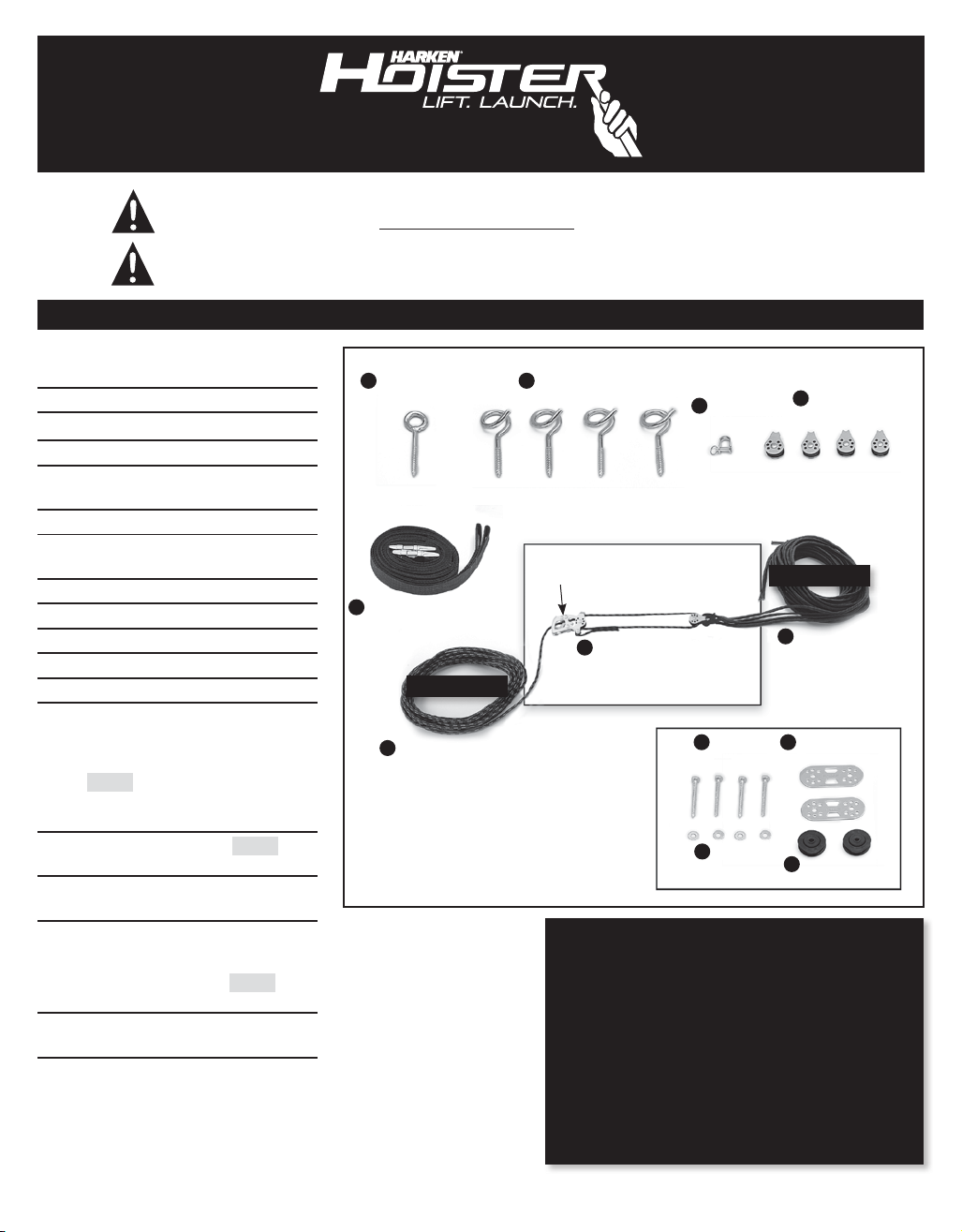
KIT INCLUDES
A1welded screw eye
B4pigtail lag screws
C1shackle
D4pulleys
E2webbing straps with buckles
7' (2.13 m)
F1single black/red hoisting rope
G1block and tackle with
cleat (G1) and rope
H4black drop ropes: 2 long, 2 short
I4lag bolts 1/4" x 21/2" (6 x 63 mm)
J4washers 1/4" (6 mm)
K2organizer plates
L2organizer pulleys
PURCHASE SEPARATELY IF NEEDED –
See “note” Step 1B, page 6.
1pine board (riser) (grade 2)
2" x 6" x 7" (50 mm x 152 mm
x 180 mm) not used for rafters
running sideways
2pine boards (grade 2) 2" x 6" x 6'
(50 mm x 152 mm x 1.83 m)
8lag bolts and washers 5/16" x 4"
(8 x 100 mm)
PURCHASE ADDITIONAL FOR RAFTERS
RUNNING SIDEWAYS – See Step 2A, page 7
1pine board (grade 2) 2" x 4" x 6'
(50 mm x 100 mm x 1.83 m)
2lag bolts and washers 5/16" x 31/2"
(8 mm x 90 mm)

2
Garage door
Front wall
Garage door Front wall
BEFORE STARTING INSTALLATION
Determine the rafter direction and follow the instructions for rafters running: FRONT-TO-BACK or SIDEWAYS
RAFTERS RUNNING FRONT-TO-BACK
RAFTERS RUNNING SIDEWAYS
3
INSTALLATION OVERVIEW
PART 1: ASSEMBLY FOR RAFTERS RUNNING FRONT-TO-BACK
INSTALLATION OVERVIEW Page 4
STEP 1: Determine Hoister location Page 5 - 6
STEP 2: Install mounting boards Page 7
STEP 3: Install pigtail lag screws Page 8
STEP 4: Install rope organizer Page 9
STEP 5: Assemble Hoister system Page 9
PART 2: ASSEMBLY FOR RAFTERS RUNNING SIDEWAYS
INSTALLATION OVERVIEW Page 10
STEP 1: Determine Hoister location Page 11 - 12
STEP 2: Install mounting boards Page 13
STEP 3: Install pigtail lag screws Page 13 - 14
STEP 4: Install rope organizer Page 14
STEP 5: Assemble Hoister system Page 15
PART 3: FOR ALL ASSEMBLIES
STEP 6: Assemble Hoister systems continued Page 16 - 17
STEP 7: Operating Hoister systems Page 18
Appendix, maintenance, and warranty Page 19
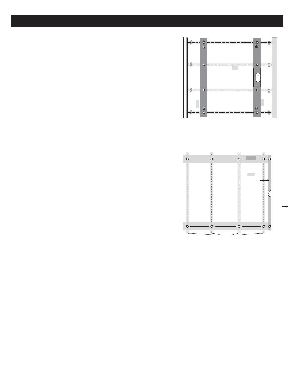
Organizer
Garage door
Front wall
Top plate
Pigtail
lag screw
Pigtail
lag screw
Pigtail
lag screw
Pigtail
lag screw
Rafter
2" x 6" x 6' (50 mm x 152 mm x 1.83 m) mounting board
2" x 6" x 7"
riser board
(50 mm x 152 mm x 180 mm)
2" x 6" x 6' (50 mm x 152 mm x 1.83 m) mounting board
Rafter
center-to-center
distance
Mounting boards
2" X 4"
(50 mm x 100 mm)
for mounting organizer –
no riser board used
Alternate position for rafters that run sideways.
Front
wall
2" x 6"
50 mm x 152 mm
Rafters
Organizer
VIEWED FROM BELOW
VIEWED FROM BELOW
4
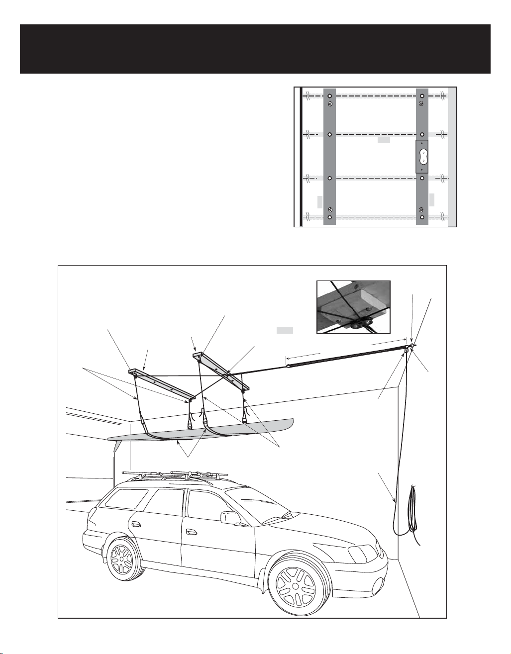
Pigtail
lag screw
(B)
Long black
drop ropes
(H)
Short black
drop ropes
(H)
Webbing straps (E)
Pulley
(D)
Welded
screw eye
(A)
Shackle
(C)
Single red/black
hoisting rope
(F)
Garage
door
Front
wall
Cleat
(G1)
Front
2" x 6"
mounting board
Back
2" x 6"
mounting board
Block and tackle (G)
Rope organizer on 2" x 6" x 7"
(50 mm x 152 mm x 180 mm) riser board
Pulleys (L) Plates (K) Lag bolts (I) Washers (J)
PART 1: ASSEMBLY FOR RAFTERS RUNNING FRONT-TO-BACK
INSTALLATION OVERVIEW
STEP 1: Determine Hoister location Page 5 - 6
STEP 2: Install mounting boards Page 7
STEP 3: Install pigtail lag screws Page 8
STEP 4: Install rope organizer Page 9
STEP 5: Assemble Hoister system Page 9
Organizer
Garage door
Front wall
Top plate
Pigtail
lag screw
Pigtail
lag screw
Pigtail
lag screw
Pigtail
lag screw
Rafter
2" x 6" x 6' (50 mm x 152 mm x 1.83 m) mounting board
2" x 6" x 7"
riser board
(50 mm x 152 mm x 180 mm)
2" x 6" x 6' (50 mm x 152 mm x 1.83 m) mounting board
VIEWED FROM BELOW

5
A. PLAN INSTALLATION
Pull car into garage with SUP on car rack.
Measure length of SUP. Position Hoister so garage door
can open with SUP lowered.
STEP 1: DETERMINE HOISTER LOCATION; RAFTERS RUNNING FRONT-TO-BACK
OPTION 1. Above garage door: Make sure there is enough
clearance to lift and store SUP above open garage door.
OPTION 2. Below garage door: Use if not enough clearance
for above garage door storage (Option 1). SUP has clearance
to lift and store below open garage door.
STORAGE OPTIONS
Measure height of SUP. Make sure SUP can be
stored above or below the open garage door.
DIAGRAM 1. Plan to position SUP above car with clearance
to open garage door. If Hoister is mounted too close to
garage door, there may not be clearance to open door.
Mounted too far forward, SUP may not balance or lower
onto car.
Opened
garage door
Opened
garage door
Opened
garage door
Opened
garage door
Opened
garage door
Opened
garage door
Other manuals for SUP
1
This manual suits for next models
4
Table of contents
Other Harken Hoister Automobile Accessories manuals

Popular Automobile Accessories manuals by other brands


ULTIMATE SPEED
ULTIMATE SPEED 279746 Assembly and Safety Advice

SSV Works
SSV Works DF-F65 manual

ULTIMATE SPEED
ULTIMATE SPEED CARBON Assembly and Safety Advice

Witter
Witter F174 Fitting instructions

WeatherTech
WeatherTech No-Drill installation instructions

TAUBENREUTHER
TAUBENREUTHER 1-336050 Installation instruction