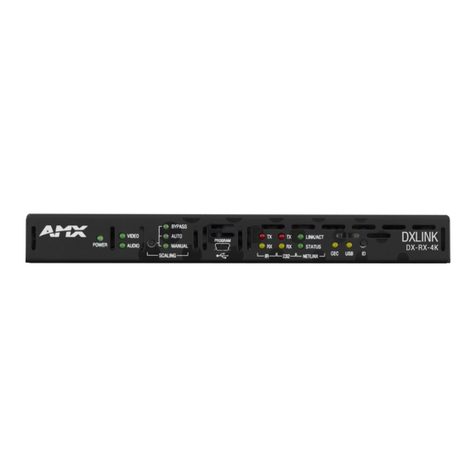
Harman AMX DX-TX-DWP-4K60-BL Quick user guide

AV FOR AN IT WORLD
HARDWARE REFERENCE MANUAL
DXLINK™ 4K60 HDMI WALLPLATE
TRANSMITTER
DX-TX-DWP-4K60-BL, DX-TX-DWP-4K60-WH

Important Safety Instructions
READ these instructions.
KEEP these instructions.
HEED all warnings.
FOLLOW all instructions.
DO NOT use this apparatus near water.
CLEAN ONLY with dry cloth.
DO NOT block any ventilation openings. Install in accordance with the manufacturer's instructions.
DO NOT install near any heat sources such as radiators, heat registers, stoves, or other apparatus (including
amplifiers) that produce heat.
PROTECT the power cord from being walked on or pinched, particularly at plugs, convenience receptacles, and the
point where they exit from the apparatus.
ONLY USE attachments/accessories specified by the manufacturer.
USE ONLY with a cart, stand, tripod, bracket, or table specified by the manufacturer, or sold with the
apparatus. When a cart is used, use caution when moving the cart/apparatus combination to avoid
injury from tip-o v e r.
REFER all servicing to qualified service personnel. Servicing is required when the apparatus has been damaged in
any way, such as power-supply cord or plug is damaged, liquid has been spilled or objects have fallen into the
apparatus, the apparatus has been exposed to rain or moisture, does not operate normally, or has been dropped.
DO NOT EXPOSE THIS APPARATUS TO DRIPPING OR SPLASHING AND ENSURE THAT NO OBJECTS FILLED WITH
LIQUIDS, SUCH AS VASES, ARE PLACED ON THIS APPARATUS.
To completely disconnect this apparatus from the AC Mains, disconnect the power supply cord plug from
the AC receptacle.
Where the mains plug or an appliance coupler is used as the disconnect device, the disconnect device
shall remain readily operable.
DO NOT overload wall outlets or extension cords beyond their rated capacity as this can cause electric shock or fire.

Warnings
ESD Warning: The icon to the left indicates text regarding potential danger associated with the discharge of
static electricity from an outside source (such as human hands) into an integrated circuit, often resulting in damage
to the circuit.
WARNING: To reduce the risk of fire or electrical shock, do not expose this apparatus to rain or moisture.
WARNING: No naked flame sources - such as candles - should be placed on the product.
WARNING: Equipment shall be connected to a MAINS socket outlet with a protective earthing connection.
WEEE Notice
The Directive on Waste Electrical and Electronic Equipment (WEEE), which entered into force as European law on
14/02/2014, resulted in a major change in the treatment of electrical equipment at end-of-life.
The purpose of this Directive is, as a first priority, the prevention of WEEE, and in addition, to promote the reuse,
recycling and other forms of recovery of such wastes so as to reduce disposal. The WEEE logo on the product or on
its box indicating collection for electrical and electronic equipment consists of the crossed-out wheeled bin, as shown
below.
This product must not be disposed of or dumped with your other household waste. You are liable of dispose of all
your electronic or electrical waste equipment by relocating over to the specified collection point for recycling of such
hazardous waste. Isolated collection and proper recovery of your electronic and electrical waste equipment at the
time of disposal will allow us to help conserving natural resources. Moreover, proper recycling of the electronic and
electrical waste equipment will ensure safety of human health and environment. For more information about
electronica and electrical waste equipment disposal, recovery, and collection points, please contact your local city
center, household waste disposal service, shop from where you purchased the equipment, or manufacturer of the
equipment.
RoHS Compliance
This product is in compliance with Directive 2011/65/EU and (EU) 2015/863 of the European Parliament and of the
Council of 31/03/2015 on the restriction of the use of certain hazardous substances in electrical and electronic
equipment.
REACH
REACH (Regulation No 1907/2006) addresses the production and use of chemical substances and their potential
impacts on human health and the environment. Article 33 (1) of REACH Regulation requires suppliers to inform the
recipients if an article contains more than 0.1% (per weight per article) of any substance(s) on the Substances of
Very High Concern (SVHC) Candidate List (‘REACH candidate list’).
This product contains the substance ‘’lead’’ (CAS-No. 7439-92-1) in a concentration of more than 0.1% per weight.
At the time of release of this product, except for the lead substance, no other substances of REACH candidate list
are contained in a concentration of more than 0.1% per weight in this product.
Note: On June 27, 2018, lead was added to the REACH candidate list. The inclusion of lead in the REACH candidate
list does not mean that lead-containing materials pose an immediate risk or results in a restriction of permissibility
of its use.

CAUTION FCC AND IC STATEMENT FOR USERS (USA AND CANADA ONLY)
This device complies with part 15 of the FCC Rules. Operation is subject to the following two conditions: (1) this
device may not cause harmful interference, and (2) this device must accept any interference received, including
interference that may cause undesired operation.
CAN ICES-3 (B)/NMB-3(B)
FCC SDOC SUPPLIER’S DECLARATION OF CONFORMITY
This equipment has been tested and found to comply with the limits for a Class B digital device, pursuant to Part 15
of the FCC Rules. These limits are designed to provide reasonable protection against harmful interference in a
residential installation. This equipment generates uses and can radiate radio frequency energy and, if not installed
and used in accordance with the instructions, may cause harmful interference to radio communications. However,
there is no guarantee that interference will not occur in a particular installation. If this equipment does cause harmful
interference to radio or television reception, which can be determined by turning the equipment off and on, the user
is encouraged to try to correct the interference by one or more of the following measures:
-- Reorient or relocate the receiving antenna.
-- Increase the separation between the equipment and receiver.
-- Connect the equipment into an outlet on a circuit different from that to which the receiver is connected.
-- Consult the dealer or an experienced radio/TV technician for help.
Changes or modifications not expressly approved by the party responsible for compliance could void the user's
authority to operate the equipment.
Caution: Changes or modifications not expressly approved by Harman could void the user’s authority to operate the
equipment.

CONTENTS
INTRODUCTION .................................................................................................................................................................................. 6
OVERVIEW............................................................................................................................................................................................................... 6
FEATURES ................................................................................................................................................................................................................ 6
PACKAGE CONTENTS ......................................................................................................................................................................................... 6
SPECIFICATIONS ................................................................................................................................................................................................... 7
TRANSMISSION DISTANCE........................................................................................................................................................................... 7
HARDWARE DESCRIPTION................................................................................................................................................................................ 8
PINOUT INFORMATION.................................................................................................................................................................... 9
RS-232...................................................................................................................................................................................................................... 9
TWISTED PAIR CABLE.......................................................................................................................................................................................... 9
INSTALLATION AND WIRING........................................................................................................................................................ 10
MOUNTING OPTIONS FOR WALLPLATE................................................................................................................................................... 10
WIRING .................................................................................................................................................................................................................. 10
STEPS FOR DEVICE WIRING ........................................................................................................................................................................... 10
APPLYING POWER......................................................................................................................................................................................... 11
RS-232 OPERATION......................................................................................................................................................................... 12
RS-232 SWITCH SETTINGS............................................................................................................................................................................. 12
RS-232 PASS-THROUGH................................................................................................................................................................................ 12
CHANGE RS-232 BAUD RATE ....................................................................................................................................................................... 13
UPGRADE.............................................................................................................................................................................................................. 13
WARRANTY TERMS AND CONDITIONS ..................................................................................................................................... 14

HARDWARE MANUAL – DX-TX-DWP-4K60 | 6
Introduction
Overview
The AMX DXLink 4K60 HDMI Wallplate Transmitter is a 4K60 4:4:4 capable distance transport solution
with support for HDMI 2.0 and HDCP 2.2. It transmits audio, video, and USB 2.0 over one shielded Cat6A
or Cat7 standard twisted pair cable. DXLink 4K60 HDMI Wallplate Transmitters are perfect for sending
HDMI and control signals over long distances to remote DXLink 4K60 Receiver Modules or other
compatible AMX Receivers such as the DGX DXLink 4K60 Twisted Pair Input Board or DVX 4K60 All-In-
One Presentation Switchers. The transmitter's built-in USB Host port can be connected to a laptop to
provide access to USB devices such as a room camera or soundbar, connected to a DXLink receiver near
a display.
Features
HDMI 2.0 4K60 4:4:4 Over Distance - Ideal for users running critical viewing applications such as
operations centers requiring transport which uses the full fidelity of their displays.
HDCP 2.2 - Supports the latest video standards to realize the full capabilities of HDMI interfaces.
High Dynamic Range (HDR) and Deep Color Support – Support for HDR10 and up to 36-bit Deep
Color.
USB 2.0 - High-speed USB 2.0 data from devices like web cameras and storage devices are
transmitted without the need for separate cables.
RS-232 pass through - Support bidirectional RS-232 pass through to a remote DXLink 4K60 or
DXLite 4K60 HDMI receiver.
Always, Just One Cable - Video, audio and USB are delivered over a single twisted pair cable. 4K60
4:4:4 can be transmitted up to 40m when using Cat6a shielded cable or better.
Powered locally or remotely - Support power supplied by a desktop power supplier or a DXLink
power sourcing device, such as Enova DGX DXLink 4K60 Twisted Pair Input Boards or Enova DVX-
4K All-In-One Presentation Switchers.
Easy Installation - Mounts in standard single-gang backbox
Package Contents
1 x DX-TX-DWP-4K60 Transmitter
1 x Power Adaptor with US, EU, UK, AU and CN Plugs
1 x Single Gang US Socket Cover (with Screws)
1 x Phoenix Connector (3.5mm, 3 Pins)
2 x Mounting Screws
1 x Safety Sheet
1 x China RoHS Declaration of Conformity
1 x Quick Start Guide

HARDWARE MANUAL – DX-TX-DWP-4K60 | 7
Specifications
Technical
Input/Output
1 x HDMI IN, 1 x USB HOST, 1 x DXLINK OUT, 1 x RS-232 (3.5mm, 3-Pin
Phoenix Port), 1 x DC 12V IN (2-Pin Phoenix Port)
Input Signal Type
HDMI 2.0 with 4K@60Hz 4:4:4, HDCP 2.2
Input Resolution
Supported
VESA:
800x6008, 1024x7688, 1280x7688,1280x8008, 1280x9608,
1280x10248, 1360x7688, 1366x7688, 1440x10508, 1440x9008
1600x9008, 1600x12008, 1680x10508, 1920x12008
SMPTE:
1280x7201,2,3,4,6,7,8, 1920x1080I6,8, 1920 x 1080P1,2,3,4,6,7,8,
3840x21602,3,5,6,8, 4096x21602,3,5,6,8
1 = at 23.98 Hz, 2 = at 24 Hz, 3 = at 25 Hz, 4 = at 29.97 Hz, 5 = at 30
Hz, 6 = at 50 Hz, 7 = at 59.94 Hz, 8 = at 60 Hz
Note:
Supports maximum DCI 4K@60 4:2:0 (4096x2160@60Hz);
Supports maximum UHD 4K@60 4:4:4 (3840x2160@60Hz).
Maximum Pixel Clock
600 MHz
Maximum Data Rate
18Gbps
Output Signal Type
HDBaseT 2.0
Video Impedance
100 Ω
Audio Format
Supported
Fully supports audio formats in HDMI 2.0 specification, including PCM
2.0/5.1/7.1, Dolby TrueHD, Dolby Atmos, DTS-HD MA and DTS:X
General
Operating Temperature
0°C to 40°C (32°F to 104°F)
Storage Temperature
-40°C to 85°C (-40°F to 185°F)
Humidity
10% to 90%, non-condensing
ESD Protection
Human-body Model:
±15kV (Air-gap discharge)
±8kV (Contact discharge)
Surge Protection
Voltage: ±1 kV
Power Supply
DC 12V 1.5A or powered by Enova DGX Switchers/DVX Switchers
Power Consumption
(Maximum)
5.5W
Device Dimension
(H x W x D)
107.5mm x 51mm x 45.3mm / 4.23’’ x 2’’ x 1.78’’
Product Weight
Approx. 0.20kg / 0.44lb
Certification
CE/FCC/UL/RoHS/REACH/CP65
Transmission Distance
Note: T568B straight-through Category cable is recommended.
Cable Type
Range
Supported Video
Cat 5e/6 60m/197ft
1080P@60Hz
Cat 6a/7 70m/230ft
Cat 5e/6 35m/115ft 4K@30Hz 4:4:4
4K@60Hz 4:4:4
Cat 6a/7 40m/131ft

HARDWARE MANUAL – DX-TX-DWP-4K60 | 8
Hardware Description
POWER LED: On indicates when the Transmitter is powered on.
HDMI LED: On indicates the HDMI signal is input, off indicates no HDMI signal input.
LINK LED: On indicates the DXLink twisted pair cable is connected and an active link is established,
off indicates the DXLink twisted pair cable isn’t connected or no active link is established.
HDMI Input: Connect to an HDMI input source.
USB HOST: Connect to a USB host device for USB pass-through.
RS-232 Switch: Set the function of RS-232 port between “PASS THROUGH” or “PROGRAM” (See “RS-
232 Switch Function” section to get detail information).
DXLink Output: Connect to a 4K60 DXLink receiver or 4K60 DXLink input board via a twisted pair
cable.
DC 12V: Connect to the provided power supply.
RS-232: Connect to an RS-232 device for RS-232 pass-through or connect to a PC for firmware
upgrades.

HARDWARE MANUAL – DX-TX-DWP-4K60 | 9
Pinout Information
RS-232
Connects to a RS-232 device with the 3-pole, 3.5mm captive screw connectors. Wire as shown below:
Twisted Pair cable
The pinout in the following picture is for twisted pair cable that connects to the DXLink connector on
Transmitters. Use either the T568A or T568B pinout specification for termination of the twisted pair cable
used between the units in a standalone setup or between Transmitters and Receivers and an enclosure
in a full system.
In a typical installation, the cables should be stretched to their full length between Transmitters and
Receivers and the enclosure or between units in a standalone system. Service loops or coils of the cable
may reduce the overall cable performance and should be minimized whenever possible.
Up to 70m
Up to 70m

HARDWARE MANUAL – DX-TX-DWP-4K60 | 10
Installation and Wiring
Mounting Options for Wallplate
The DXLink 4K60 HDMI wallplate transmitter mounts in a standard US single gang back box. Standard
decora style cover plates are provided to allow matching the individual decor of an environment or
matching other standard decor covers in a room/area.
IMPORTANT: Be sure to measure the back box and any other components used to mount the Wallplate
prior to installation/construction to ensure the unit fits (e.g., some mud rings do not work unless their
corners are modified).
Wiring
Warnings:
Before wiring, disconnect the power from all devices.
Before wiring, please see “RS-232 Switch Function” section to do the corresponding configurations.
When connecting with a DGX switcher, power requirements must be determined. (See “Applying Power” of
“Installation and Wiring” section).
During wiring, connect and disconnect the cables gently.
Steps for Device Wiring
a) Extender Mode (Standalone)
A Transmitter and Receiver standalone pair can work together as an extender solution for
transmission of HDMI over twisted pair cable.
1. Connect a high-quality category cable to DXLINK ports between transmitter and receiver (DX-
RX-4K60 or DXL-RX-4K60).
2. Connect an HDMI source (such as PC) to the HDMI IN port of the transmitter with a high-
quality HDMI cable.
3. Connect HDMI display (such as TV or projector) to the HDMI OUT port of receiver.
4. For additional control options:
USB Control: Connect a USB Host PC to the USB HOST port of the transmitter and connect a
USB device (such as a keyboard or mouse) to USB port of the receiver. The USB device can
be connected to the host PC.
RS-232 Pass-Through: Set the RS-232 switch of the transmitter to “PASS THROUGH”.
Connect a RS-232 host (or client) device to RS-232 port of the transmitter, and a client (or
host) device to RS-232 port of the receiver. The RS-232 serial signal will be passed through
bi-directionally.
5. Connect the transmitter and the receiver with the power adapters.

HARDWARE MANUAL – DX-TX-DWP-4K60 | 11
b) Endpoint Mode (Switcher)
The primary function of the Transmitters is to work with compatible DXLink equipment as an endpoint
solution for transmission of HDMI over twisted pair cable.
1. Connect one or more transmitters to the 4K60 DXLink input board of the DGX or the DXLink input
ports of the DVX-4K switcher and connect one or more receivers to the 4K60 DXLink output board
of the DGX or the DXLink output ports of DVX-4K switcher.
2. Connect an HDMI source (such as PC) to the HDMI IN port of the transmitter with a high-quality
HDMI cable.
3. Connect HDMI displays (such as TVs or projectors) to HDMI OUT ports of the receivers.
Applying Power
A desktop power supply is provided with each module. Automatic power supply to DXLink twisted pair
transmitter and receiver units are as follows:
Over local power by connecting the supplied desktop power supply to the 12V input.
Over the DXLink connection from a powered DXLink port on a DGX or DVX.
NOTE: Local power takes precedence over DXLink power.
Power Budget
For TXs and/or RXs connected to an Enova DGX, use the Enova DGX Configuration Tool
(www.amx.com/enova) to determine power requirements of a configuration and if any DXLink TXs or RXs
should use local power.
IMPORTANT: If a desktop power supply is used to power the unit, it must be the one provided, which must
not be altered in any way. AMX does not support the use of any other power supplies or PoE injectors as
they may potentially damage the DXLink equipment.
LED Status Indicators:
INDICATOR LED
NORMAL POWER UP
INDICATES
PWR
Green
The transmitter is powered on.
HDMI Green or Off Green: The HDMI signal is input.
Off: No HDMI signal input.
LINK Green or Off Green: DXLink signal is normal.
Off: No DXLink signal or link error.

HARDWARE MANUAL – DX-TX-DWP-4K60 | 12
RS-232 Operation
RS-232 Switch Settings
The wallplate transmitter features a slide switch to set RS-232 function, the RS-232 switch is as shown
in the following figure. By default, it is set to “PASS THROUGH”.
PASS THROUGH: When the transmitter is connected to a DXLink 4K60 receiver or DXLite 4K60
receiver directly, set the RS-232 switch to “PASS THROUGH” function, the transmitter and the
receiver support transmitting RS-232 signal bi-directionally.
PROGRAM: Connect the RS-232 port of the transmitter to a PC, upgrade the firmware.
RS-232 Pass-through
The RS-232 port are the 3-position screw terminal blocks (see “Pinout Information” Section) on the rear
of the modules.
Under Extender Mode, the serial data can be passed through between the wallplate transmitter and the
receiver. Wire these ports to supply serial data along with the associated video and audio signals from a
source device (over the twisted pair cable between the Transmitter Module and the Receiver Module) to
a destination device or vice versa from the Receiver Module to the Transmitter Module. For more detail,
see the “Wiring” part of “Installation and Wiring” section.
Note: More detail information about the RS-232 function of the connected receiver, please refer to its
own manual on www.amx.com.

HARDWARE MANUAL – DX-TX-DWP-4K60 | 13
Change RS-232 Baud Rate
The default baud rate of the RS-232 port is 115200. Users can use API commands to change the RS-232
baud rate.
Set the RS-232 switch to “PASS THROUGH” and connect the RS-232 port to the PC, ensure a serial port
assistant is downloaded on the PC. Launch the serial port assistant, set the correct port number and
baud rate, and click “Open”. The default baud rate to send commands is 115200. Use command “SET
BAUD_RATE XXX<CR><LF>” to change baud rate.
Note: <CR><LF> denotes a carriage return or a line feed; all commands must be ended up with a carriage
return or a line feed
For example:
Input: SET BAUD_RATE 9600<CR><LF>
Response: baudrate 9600
Note: When upgrading firmware, the baud rate must be set to 115200.
Upgrade
The transmitter supports upgrading firmware through RS-232 port on the rear panel. Please contact AMX
technical support for firmware upgrades.

© 2024 Harman. All rights reserved. SmartScale, NetLinx, Enova, AMX, AV FOR AN IT WORLD, and HARMAN, and their respective logos are registered
trademarks of HARMAN. Oracle, Java and any other company or brand name referenced may be trademarks/registered trademarks of their respective
companies.
AMX does not assume responsibility for errors or omissions. AMX also reserves the right to alter specifications without prior notice at any time. The AMX
Warranty and Return Policy and related documents can be viewed/downloaded at www.amx.com.
3000 RESEARCH DRIVE, RICHARDSON, TX 75082 AMX.com | 800.222.0193 | 469.624.8000 | +1.469.624.7400 | fax 469.624.7153
Last Revised: 2024-01-11
Warranty Terms and Conditions
For the following cases AMX shall charge for the service(s) claimed for the products if the product is still remediable
and the warranty card becomes unenforceable or inapplicable.
1. The original serial number (specified by AMX) labeled on the product has been removed, erased, replaced,
defaced or is illegible.
2. The warranty has expired.
3. The defects are caused by the fact that the product is repaired, dismantled or altered by anyone that is not from
an AMX authorized service partner. The defects are caused by the fact that the product is used or handled
improperly, roughly or not as instructed in the applicable User Guide.
4. The defects are caused by any force majeure including but not limited to accidents, fire, earthquake, lightning,
tsunami and war.
5. The service, configuration and gifts promised by salesman only but not covered by normal contract.
6. AMX preserves the right for interpretation of these cases above and to make changes to them at any time without
notice.
This manual suits for next models
1
Table of contents
Other Harman Transmitter manuals