Harmonic Drive CSF-3 Series User manual

For Precision Control
HarmonicDriveSpeed Reducer
CSF-3 Series Manual
●Thank you very much for your purchasing our HarmonicDrive
CSF-3 series.
●Be sure to use sufficient safety measures when installing and
operating the equipment so as to prevent an accident resulting in
a serious physical injury damaged by a malfunction or improper
operation.
●Product specifications are subject to change without notice for
improvement purposes.
●Keep this manual in a convenient location and refer to it
whenever necessary in operating or maintaining the units.
●The end user of the driver should have a copy of this manual.
ISO14001
ISO9001

SAFETY GUIDE
For HarmonicDrive®component and unit
Read this manual thoroughly before designing the application, installation, maintenance or inspection of the actuator.
SYSTEMS
Indicates a potentially hazardous situation,
which, if not avoided, could result in death
or serious personal injury.
Indicates a potentially hazardous situation, which, if
not avoided, may result in minor or moderate personal
injury and/or damage to the equipment.
WARNING
CAUTION
LIMITATION OF APPLICATIONS:
The equipment listed in this document may not be used for the applications listed below:
Space equipment Amusement equipment
Aircraft, aeronautic equipment Machine or devices acting directly on the human body
Nuclear equipment Instruments or devices to transport or carry people
Household apparatus Apparatus or devices used in special environments
Vacuum equipment Instruments or devices to prevent explosion
Automobile, automotive parts
Safety measures are essential to prevent accidents resulting in death, injury or damage of the equipment due to
lfunction or faulty operation.ma
Design Precaution: Be certain to read the catalog when designing the equipment.
Use only in a specified environment.
●Please ensure the following environmental conditions
are complied with:
- Ambient temperature 0 to 40°C .
- No contamination by water, oil
- No corrosive or explosive gas
- No dust such as metal powder
Install the equipment in a specified manner.
●Carry out assembly precisely in the specified order
according to the catalog.
●Observe our recommended tightening methods (such
as bolts used).
●Operating the equipment without precise assembly can
cause troubles such as generation of vibration,
reduction of life, deterioration of precision and
breakdown. Use the specified lubricant.
Install the equipment in a specified precision.
●Design and assemble parts to keep the
recommended installation precision on the catalog.
●Failure to keep the precision can cause troubles such
as generation of vibration, reduction of life,
deterioration of precision and breakdown.
Use the specified lubricant.
●Using other lubricant than our recommended products
can reduce the life. Replace the lubricant in a specified
condition.
●Grease is sealed in a unit product. Do not mix other
kinds of grease.
Operational Precaution: Be certain to read the catalog before operating the equipment.
Be careful in handling products and parts.
●Do not give strong shock to parts and units with a
hammer. Do not scratch or bruise them. Possible
damage is assumed.
●If you use the equipment in a damaged condition, the
specified performance may not be retained. It can
also cause troubles such as breakdown.
Apply torque within the allowable range.
●Do not apply torque exceeding the instantaneous
allowable max. torque. Applying excess torque can
cause troubles such as loose tightening bolts,
generation of backlash and breakdown.
●Striking an arm directly attached to the output shaft can
damage the arm and make the output shaft
uncontrollable.
Do not change a set of parts.
●The product is manufactured with sets of parts. the
specified performance may not be retained if you
have used mixed sets of parts.
Do not break down unit products.
●Do not break down and reassemble unit products.
Original performance may not be reproduced.
Handling lubricant
Precautions on handling lubricant
●Lubricant got in the eye can cause an inflammation.
Wear protective glasses to prevent it from getting in
your eye when you handle it.
●Lubricant coming in contact with the skin can cause
an inflammation. Wear protective gloves to prevent it
from contacting your skin when you handle it.
●Do not eat it (to avoid diarrhea and vomiting).
●When you open the container, you might have your
hand cut by it. Wear protective gloves.
●Keep lubricant off children.
Treatment of waste oil and containers
●Treatment methods are obliged by law. Treat wastes
appropriately according to the law. If you are unsure
how to treat them, you should consult with the dealer
before treating them.
●Do not apply pressure on an empty container. The
container may blow up.
●Do not weld, heat, drill or cut the container. The
remainder may ignite with an explosion.
First-aid
●If lubricant gets in your eye, you should wash your
eye with clean water for 15 minutes and submit to
medical treatment.
●If lubricant comes in contact with your skin, you
should thoroughly wash it with water and soap.
●If you swallowed it, you should immediately submit to
medical treatment without throwing it up by
constraint.
Storage
●Tightly plug the container after use to prevent intrusion
of dusts and water. Avoid direct sunlight to store
lubricant in a dark place.
Disposal
Please discard as industrial waste.
●Please discard as industrial waste when discarding.
C
A
U
TI
O
N
C
A
U
TI
O
N
CAUTION
C
A
U
TI
O
N
CAUTION
C
A
U
TI
O
N
WARNIN
G
WARNIN
G
C
A
U
TI
O
N
C
A
U
TI
O
N
C
A
U
TI
O
N
C
A
U
TI
O
N
C
A
U
TI
O
N

CSF-3 series manual
- Contents 1 -
Contents
Chapter 1 Outlines of CSF-3 series..................................................................................................... 1
1-1 Model and sign.......................................................................................................................... 1
1-2 Model ........................................................................................................................................ 1
1-3 External drawing ....................................................................................................................... 2
Chapter 2 Installing of Motor................................................................................................................ 3
2-1 Checking procedure.................................................................................................................. 3
2-2 Main bearing specification ........................................................................................................ 3
2-3 How to obtain the maximum load moment load........................................................................ 4
2-4 How to obtain the average load................................................................................................ 4
2-5 How to obtain the radial load coefficient (X) and axial load coefficient (Y)............................... 5
2-6 How to obtain the life................................................................................................................. 5
2-7 How to obtain the life under oscillating movement ................................................................... 6
2-8 How to obtain the static safety coefficient.................................................................................6
Chapter 3 Efficiency characteristics ................................................................................................... 7
3-1 Double-axial unit type (1U) ....................................................................................................... 7
3-2 Gear head type (1U-CC)........................................................................................................... 8
Chapter 4 No-load running torque..................................................................................................... 10
Chapter 5 Starting torque and Overdrive starting torque ................................................................11
Chapter 6 Ratcheting torque and Buckling torque.......................................................................... 12
Chapter 7 Angle transmission accuracy........................................................................................... 13
Chapter 8 Vibration ............................................................................................................................. 14
Chapter 9 Rigidity................................................................................................................................ 15
Chapter 10 Design and Precautions on assembly........................................................................... 17
10-1 Embedding accuracy of gear head type (1U-CC)................................................................... 17
10-2 Tolerable load of input shaft of double-shaft unit type (1U) .................................................... 18
10-3 Mounting in system................................................................................................................. 19
10-4 Mechanical accuracy .............................................................................................................. 20
10-5 Lubricant ................................................................................................................................. 20

CSF-3 series manual
- Contents 2 -
Memo

Chapter 1 Outlines of CSF-3 series
- 1-
This supplementary technical data incorporates technical data that is not included in our CSF-3
Series Catalog.
Please use this data hand in hand with the CSF-3 Series Catalog when you study the use of
Harmonic Drive products in the design of your products.
Chapter 1 Outlines of CSF-3 series
1-1 Model and sign
Model and sign of CSF-3 series are described as follows:
CSF-3 B-50-1U-CC-□□
①②③④⑤⑥
①
Model name
HarmonicDrive CSF series
②
Model No.
3
③
Desing
Version
B
(
New Version
)
④
Reduction ratio
30:1/30 50:1/50 100:1/100
⑤
Model
1U:Double-shaft unit type
1U-CC:Gear head type
⑥
Specification
None=standard product
SP=special specifications
such as shapes
and performance
1-2 Model
Model Reduction
ratio
Rated torque at
input 2000r/min
Peak torque at
start/stop
Allowable
max. value of
ave. load
torque
Instantaneous
Allowable
max. torque
Allowable
max. input
rotational
speed
Allowable
ave. input
rotational
speed
Inertia moment
(1/4GD2)
Nm
kgf m
Nm
kgf m
Nm
kgf m
Nm
kgf m
r/min
r/min
kgcm2
3
30
0.06
0.006
0.13
0.013
0.10
0.010
0.22
0.022
10000 6500 1U:5.3×10⁻⁷
1U-CC:7.0×10⁻⁷
50
0.11
0.011
0.21
0.021
0.13
0.013
0.41
0.040
100
0.15
0.015
0.30
0.029
0.23
0.023
0.57
0.056
Note) Upper part of inertia moment is the value of 1U type, whereas, lower part is the value 1U-CC type.
Note) See the catalog in description of terms on the rated table.

Chapter 1 Outlines of CSF-3 series
- 2-
1-3 External drawing
■Double-shaft unit type【CSF-3-XX-1U】
Unit: mm
Mass: 13.7g
■Gear head type【CSF-3-XX-1U-CC】
Unit: mm
Mass: 11.4g
Note) Please confirm the dimensions specification drawing issued by us for detail.
4-M1.6 tap 3.2
evenly spaced
4-M1.6 tap 3.2
evenly spaced
Maximum diameter of rotation part
Maximum diameter of rotation part
4-M1.4 tap 2.8
evenly spaced

Chapter 2 Installing of Motor
3
Chapter 2 Installing of Motor
A precision cross roller bearing is built in the unit type and the gear head type to directly support the
external load (output flange) (precision 4-point contact ball bearing for the CSF-mini series).
Check the maximum load moment load, life of the bearing and static safety coefficient to fully bring out
the performance of the unit type.
2-1 Checking procedure
(1) Checking the maximum load moment load
Obtain the maximum load moment load (Mmax).
⇓
Maximum load moment load (Mmax)
≤
permissible moment (Mc)
(2) Checking the life
Obtain the average radial load (Frav) and the average axial load (Faav).
⇓
Obtain the radial load coefficient (x) and the axial load coefficient (y).
⇓
Calculate the life and check it.
(3) Checking the static safety coefficient
Obtain the static equivalent radial load coefficient (Po).
⇓
Check the static safety coefficient.
2-2 Main bearing specification
Table 1 Specification
Model No.
Ball pitch
circle
diameter
(dp)
Offset
(R)
Basic rated load Moment
load Moment rigidity Tolerable radial
load
Tolerable
thrust load
Basic dynamic
rated load
Basic static rated
load
m m ×102N ×102N Nm Nm/rad N N
3 0.0077 0.0041 6.65 4.24 0.27 0.9×10236 130

Chapter 2 Installing of Motor
4
2-3 How to obtain the maximum load moment load
How to obtain the maximum load moment load is shown below. Check Mmax <=Mc.
●Formula (1)
Symbol of Formula (1)
Frmax
Maximum radial
load
N(kgf) See Figure 1.
Famax
Maximum axial
load
N(kgf) See Figure 1.
Lr ,La
――――
m
See Figure 1.
R Offset amount m
See Figure 1
and Table 1.
2-4 How to obtain the average load
(Average radial load, average axial load, average output rotational frequency)
If the radial load and the axial load fluctuate, they should be converted into the average load to check the
life of the 4-point contact bearing.
●Formula (2) How to obtain the average radial load (Frav)
Note that the maximum radial load within the t1 section is Fr1
and the maximum radial load within the t2 section is Fr2.
●Formula (3) How to obtain the average axial load (Faav)
Note that the maximum axial load within the t1 section is Fa1
and the maximum axial load within the t2 section is Fa2.
●Formula (4) How to obtain the average output rotational frequency (Nav)
Mmax=Frmax(Lr+R)+Famax・La
Figure 1External load influence diagram
n
n
nnn
av
tntntn
Fr(t
nFr(tnFr(tn
Fr
2211
222111
3
+++
+
=
+
333
)))
nn
nnn
av
tntntn
Fa(tnFa(tnFa(tn
Fr
2211
222111
3
+++
+
=
+
333
)))
n
nn
av
ttt
tntntn
N
21
2211
+++
+++
=
Axial load
output
rotational
frequency
Graph: Load pattern and output
rotational frequency
Radial load
Time
Time
Time
Fixed
Lr
R
L
L/2
F
R
La
dp
Radial load Fr
Axial load Fa

Chapter 2 Installing of Motor
5
2-5 How to obtain the radial load coefficient (X) and axial
load coefficient (Y)
●Formula (5) Table 2
X
Y
1.5
La)/dpFaR)
(Lr(Fr
Fr
Fa ≤
⋅++
+
avavav
av
2
1 0.45
1.5
La)/dp
FaR)(Lr(FrFr
Fa >
⋅
+++
avavav
av
2
0.67 0.67
Symbol of Formula (5)
Frav
Average radial load
N(kgf)
See “Average load.”
Faav
Average axial load
N(kgf)
See “Average load.”
Lr ,La
―
m
See Figure 1.
R
Offset amount
m
See Figure 1 and Table 1.
dp
Pitch circle diameter of a roller
m
See Figure 1 and Table 1.
2-6 How to obtain the life
Obtain the life of the 4-point contact bearing by Formula (6).
You can obtain the dynamic equivalent radial load (Pc) by Formula (7).
●Formula (6)
Symbols of Formula (6)
LB-10
Life
hour
Nav
Average output rotational speed
r/min
See “How to obtain the average load.”
C
Basic dynamic load rating
N(kgf)
See Table 1.
Pc
Dynamic equivalent radial load coefficient
N(kgf)
See Formula (7).
fw
Load coefficient
―
See Table 3.
Table 3 Load coefficient
Load status
fw
During smooth operation without shock or vibration
1
~
1.2
During normal operation
1.2
~
1.5
During operation with shock and vibration
1.5
~
3
●Formula (7)
Symbols of Formula (7)
Frav
Average radial load
N(kgf)
See “How to obtain the average load.”
Faav
Average axial load
N(kgf)
See “How to obtain the average load.”
dp
Pitch circle diameter of a roller
m
See Figure 1 and Table 1.
X
Radial load coefficient
See Table 2.
Y
Axial load coefficient
See Table 2.
Lr,La
m
See Figure 1.
R
Offset amount
m
See Figure 1 and Table 1.
)
Pc•fw
C
(×
N×
=
L
B
3
6
10
60
10
av
Fa•Y+)
dp
)La•Fa+)R+
Lr(Fr(
(•X=Pc av
avav2

Chapter 2 Installing of Motor
6
2-7 How to obtain the life under oscillating movement
Obtain the life of the bearing under oscillating movement by Formula (8).
●Formula (8)
Symbols of Formula (8)
Loc
Rated life under oscillating
movement
hour
n1
Number of reciprocating
oscillations per minute
cpm
C
Basic dynamic load rating
N(kgf)
See Table 1.
Pc
Dynamic equivalent radial
load coefficient
N(kgf) See Formula (7).
fw
Load coefficient
See Table 3.
θOscillating angle/2
Angl
e
See Figure 2.
2-8 How to obtain the static safety coefficient
In general, the basic static load rating (Co) is considered to be the permissible limit of the static
equivalent load. However, obtain the limit based on the operating and required conditions.
Obtain the static safety coefficient of the cross roller bearing by Formula (9). General values under the
operating condition are shown in Table 4. You can obtain the static equivalent radial load (Po) by
Formula (10).
●Formula (9)
Symbols of Formula (9)
Co
Basic static load rating
N(kgf)
See Table 1.
Po
Static equivalent radial load coefficient
N(kgf)
See Formula (10).
Table 4 Static safety coefficient
Operating condition of the roller bearing
fs
When high rotation precision is required
≧
3
When shock and vibration are expected
≧
2
Under normal operating condition
≧
1.5
●Formula (10)
Symbols of Formula (10)
Frmax
Maximum radial load
N(kgf)
See “How to obtain the maximum load moment
load”
Famax
Maximum axial load
N(kgf)
Mmax
Maximum load moment load
Nm(kgfm)
dp
Pitch circle diameter of a roller
m
See Figure 1 and Table 1.
)
Pc
•
fw
C
(×
θ
×
n×
=Loc
3
6
90
160
10
Po
Co
=fs
Fa.+
dp
M
+Fr=Po max
max
max 440
2
Figure 2 Oscillating movement
Oscillating angle

Chapter 3 Efficiency characteristics
- 7-
Chapter 3 Efficiency characteristics
The efficiency varies depending on the following conditions.
●Reduction ratio ●Input rotational speed ●Load torque
●Temperature ●Lubrication condition (type and quantity of lubricant)
●Measuring condition
Load torque
The rated torque shown in the ratings
(see the corresponding pages on each series)
Measuring
condition
Grease lubrication
Harmonic grease SK-2
Application quantity: Appropriate application quantity
3-1 Double-axial unit type (1U)
●Reduction ratio: 30
●Reduction ratio: 50
0%
10%
20%
30%
40%
50%
60%
70%
80%
90%
100%
-10 010 20 30 40
温度 (℃)
効率(%)
500r/min
1000r/min
2000r/min
3500r/min
5000r/min
10000r/min
0%
10%
20%
30%
40%
50%
60%
70%
80%
90%
100%
-10 010 20 30 40
温度 (℃)
効率(%)
500r/min
1000r/min
2000r/min
3500r/min
5000r/min
10000r/min
100
90
80
70
60
50
40
30
20
10
0
100
90
80
70
60
50
40
30
20
10
0
Efficiency(%)
Efficiency(%)
Temperature(°C)
Temperature(°C)

Chapter 3 Efficiency characteristics
- 8-
●Reduction ratio: 100
3-2 Gear head type (1U-CC)
●Reduction ratio: 30
0%
10%
20%
30%
40%
50%
60%
70%
80%
90%
100%
-10 010 20 30 40
温度 (℃)
効率(%)
500r/min
1000r/min
2000r/min
3500r/min
5000r/min
10000r/min
0%
10%
20%
30%
40%
50%
60%
70%
80%
90%
100%
-10 010 20 30 40
温度 (℃)
効率(%)
500r/min
1000r/min
2000r/min
3500r/min
5000r/min
10000r/min
100
90
80
70
60
50
40
30
20
10
0
100
90
80
70
60
50
4
0
30
20
10
0
Efficiency(%)
Temperature(°C)
Efficiency(%)
Temperature(°C)

Chapter 3 Efficiency characteristics
- 9-
●Reduction ratio: 50
●Reduction ratio: 100
0%
10%
20%
30%
40%
50%
60%
70%
80%
90%
100%
-10 010 20 30 40
温度 (℃)
効率(%)
500r/min
1000r/min
2000r/min
3500r/min
5000r/min
10000r/min
0%
10%
20%
30%
40%
50%
60%
70%
80%
90%
100%
-10 010 20 30 40
温度 (℃)
効率(%)
500r/min
1000r/min
2000r/min
3500r/min
5000r/min
10000r/min
100
90
80
70
60
50
40
30
20
10
0
100
90
80
70
60
50
40
30
20
10
0
Efficiency(%)
Temperature(°C)
Efficiency(%)
Temperature(°C)
Chapter 4 No-load running torque
- 10 -
Chapter 4 No-load running torque
No-load running torque means the torque required to put CSF-3 under a no-load condition.
* Please contact your Harmonic Drive sales representative for more details.
●Measuring condition
Model: CSF-3-100-1U-CC (Gear Head Type)
Reduction ratio: 100
Measuring condition: Grease lubrication (Harmonic grease SK-2)
The torque value is the value after a trial run of at two hours at an input of 2000 r/min.
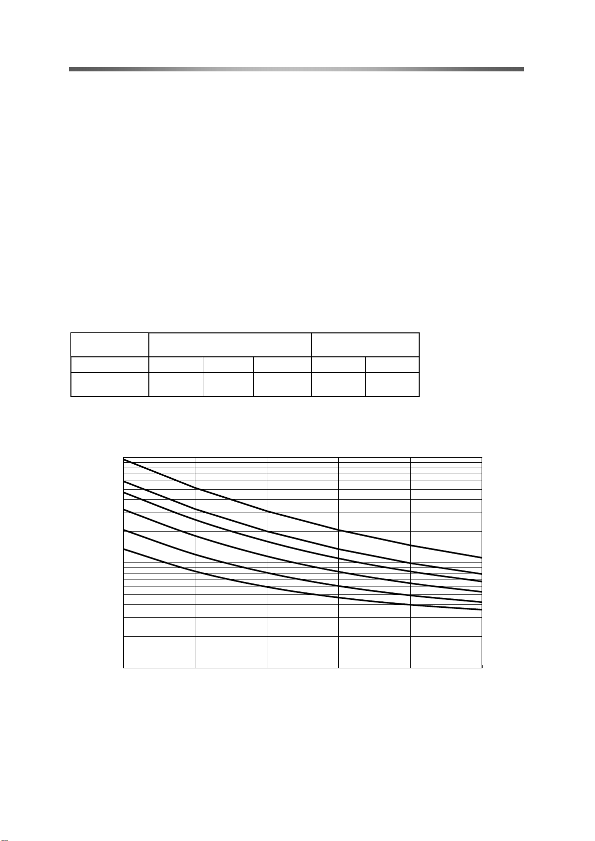
●Correction amount by reduction ratio
No-load running torques of Harmonic Drive vary in accordance with the reduction ratio. The values in
Graph 1 below are the values for the gear head type (1U-CC, reduction ratio 1/100). Other reduction
ratios can be calculated by adding correction amounts shown in Table 1.
Table 1 Unit: cNm
Double-axial unit type
(1U) Gear head type
(1U-CC)
Reduction ratio 30 50 100 30 50
Correction
amount 0.026 0.023 0.006 0.020 0.017
Graph 1 No-load running torque of gear head type (1U-CC, reduction ratio 1/100)
0.01
0.10
1.00
-10 0 10 20 30 40
温度 (℃)
無負荷ランニングトルク(cNm)
10000r/min
5000r/min
3500r/min
2000r/min
1000r/min
500r/min
Temperature °C
No-load runnin
g
tor
q
ue cNm

Chapter 5 Starting torque and Overdrive starting torque
- 11 -
Chapter 5 Starting torque and Overdrive
starting torque
●Starting torque
Starting torque means the instantaneous “starting torque” that the output side (low-speed side) starts
rotation when a torque is applied on the input side (high-speed side)
Double axial unit type(1U) Unit: cNmGear head type(1U-CC) Unit: cNm
Reduction Ratio
Starting torque
Reduction Ratio
Starting torque
30
0.34
30
0.32
50
0.30
50
0.28
100
0.26
100
0.24
●Overdrive starting torque
Overdrive starting torque means the instantaneous “starting torque” that the input side (high-speed side)
starts rotation when a torque is applied on the output side (low-speed side)
Double axial unit type(1U) Unit: cNmGear head type(1U-CC) Unit: cNm
Reduction Ratio
Overdrive
starting torque
Reduction Ratio
Overdrive
starting torque
30
0.14
30
0.12
50
0.14
50
0.11
100
0.16
100
0.13
●Measuring condition
No-load, ambient temperature: +20ºC
* Use values on the following table as reference values as they vary depending on the usage conditions.

Chapter 6 Starting torque and Overdrive starting torque
- 12 -
Chapter 6 Ratcheting torque and
Buckling torque
●Ratcheting torque
When excess impact torque is applied during operation, the engagement of the teeth between the
circular saline and the flexspline may be put momentarily out of alignment instead of damaging the
flexspline.This phenomenon is called ratcheting, and the torque is called ratcheting torque (see values
on the corresponding page of each series).0peraling the drive withoutfixing ratcheting will result in
earlier abrasion of the teeth and shorter lifespan of the wave generator bearing due to the effect of the
grinding powder generated by ratcheting.
Unit:Nm
●Buckling torque
When excess torque is applied lo the flexspline (output) with the wave generator fixed, the flexspline
causes elastic deformation,buckles on the body before long and will be destroyed. The torque at
the time is called buckling torque.
Unit:Nm
All reduction ratio
Buckling torque
3.7
Reduction ratio
Ratcheting torque
30
0.88
50
0.83
100
0.74

Chapter 7Angle transmission accuracy
- 13-
Chapter 7Angle transmission accuracy
Angle transmission accuracy indicates the difference between the logical rotating angle and the actual
rotating angle as the angle transmission error when any rotating angle is given as an input.
Example of measurement
R
=er 1
2-θ
θθ
θer ……………Angle transmission error
θ1……………Input rotating angle
θ2……………Actual output rotating angle
R……………Reduction ratio of Harmonic Drive (i=1:R)
Angle transmission accuracy (Full speed ratio)
Unit
Angle transmission
accuracy (Full speed ratio)
×10-3rad 2.9
arc min 10

Chapter 8Vibration
14
Chapter 8Vibration
The angle transmission error elements of Harmonic Drive may appear as rotating vibration of the load
side inertia.
Especially when the characteristic frequency of the vibration system including Harmonic Drive overlaps
that of the chassis or load inertia, it generates a resonant condition that amplifies angle transmission
error elements of Harmonic Drive. Observe Chapter 9 Design and Precautions on assembly.
Two angle transmission error elements of Harmonic Drive correspond to a cycle of the input shaft from
the mechanical viewpoint ofHarmonic Drive. Therefore, the frequency is double the input frequency as it
is the main element of the error.
If the characteristic frequency of the vibration system including Harmonic Drive is F=15 Hz, the input
rotating speed (N) is expressed as shown below.
N =15/2・60 = 450r/min
The resonant condition is generated in the rotating speed area (450 r/min).
●How to obtain the characteristic frequency of the vibration system including Harmonic Drive
J
K
•=f π
2
1
Symbol of the calculation formula
fThe characteristic frequency of the vibration system including Harmonic Drive : Hz
KSpring constant of Harmonic Drive: Nm/rad
JLoad inertia: kg・m2

Chapter 9 Rigidity
15
Chapter 9 Rigidity
Rigidity and backlash of the drive system greatly affects the performance of the servo system. A detailed
review of these items is required before designing the equipment and selecting a model number.
Rigidity
Fixing the input side (wave generator) and applying torque to the
output side (flexspline) generates torsion almost proportional to
the torque on the output side. Figure O18-1 shows the torsional
angle quantity on the output side when the torque applied on the
output side starts from zero, increases up to +T0 and decreases
down to –T0. This is called the “Torque – torsional angle diagram,”
which normally draws a loop of 0-A-B-A’-B’-A. The slope described
in the “Torque – torsional angle diagram” is represented as the
spring constant for the rigidity of Harmonic Drive (unit: Nm/rad).
As shown in Figure 020-2, this “Torque – torsional angle diagram”
is divided into 3 partitions, and the spring constants in the area are
represented as K1, K2 and K3.
K1 – The spring constant when the torque changes from [zero] to
[T1]
K2 – The spring constant when the torque changes from [T1] to
[T2]
K3 – The spring constant when the torque changes from [T2] to
[T3]
Torsional angle can be calculated by the following formulas.
* φ: torsional angle
◆Torque T is T1 or less:
◆Torque T is between T1 and T2:
◆Torque T is between T2 and T3:
The following table shows average values of T1 to T3, K1 to K3 and θ1 to θ2.
Spring constant
Model
No.
Sign
Unit
Reduction
ratio 30
Reduction
ratio 50
Reduction
ratio 100
3
T1
Nm
0.016
0.016
0.016
kgf m
0.0016
0.0016
0.0016
K1
Nm/rad
27
30
34
×10-4kgf m/arc min
8
9
10
θ1
×10-4rad
5.9
5.3
4.7
arc min
2.0
1.8
1.6
T2
Nm
0.05
0.05
0.05
kgf m
0.005
0.005
0.005
K2
Nm/rad
40
47
54
×10-4kgf m/arc min
12
14
16
θ2
×10-4rad
12.5
10.6
9.3
arc min
4.2
3.6
3.1
K3
Nm/rad
51
57
67
×10-4kgf m/arc min
15
17
20
3
2
2K
TT −
+θ
=ϕ
2
1
1K
TT −
+
θ=ϕ
1K
T
=ϕ
Figure 1
ね
じ
り
角
ヒステリシスロス
トルク
0
B’
B
A
+T0
-T0
A’
ね
じ
り
角
K3
K2
K1
T1
T2
トルク
0
θ1
θ2
Torsional angle
Torsional angle
Torque
Torque
Hysteresis
loss

Chapter 9 Rigidity
16
Hysteresis loss
As shown in Figure 020-1, when the torque is applied up to the rated value and is brought back to [zero],
the torsional angle does not become absolutely [zero] and a small amount remains. This is called
hysteresis loss.
Hysteresis amount
Reduction
ratio
Unit
Hysteresis amount
30
×10
-4
rad
1.3
arc min
4.5
50
×10
-4
rad
1.2
arc min
4
100
×10
-4
rad
1.2
arc min
4
Backlash
CSF-3 wave generators are of the rigid type (solid type) and are backlash free.
Table of contents
Other Harmonic Drive Industrial Equipment manuals


Popular Industrial Equipment manuals by other brands


Pepperl+Fuchs
Pepperl+Fuchs PGV100RS-F200-B16-1,5M manual

Siemens
Siemens SINUMERIK ONE NCU 1760 Equipment manual

Doosan
Doosan 7/124 Operation & maintenance manual

MoldMaker
MoldMaker MMC-11 user manual

Global Industrial
Global Industrial B237006 Assembly instructions

M-system
M-system M8DY1 instruction manual

FRANKLINWH
FRANKLINWH aPbox Installation and operation manual

Siemens
Siemens SIMATIC NET RUGGEDCOM RX1500 installation manual

ITW Dynatec
ITW Dynatec DYNAMINI 4-HOSE Technical documentation

CBE
CBE PT642 user manual

DOYMA
DOYMA Curaflex Nova Uno/M/Z installation instructions

Martin
Martin PIT VIPER installation instructions