manuals.online logo
Brands
  1. Home
  2. •
  3. Brands
  4. •
  5. Siemens
  6. •
  7. Industrial Equipment
  8. •
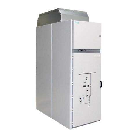
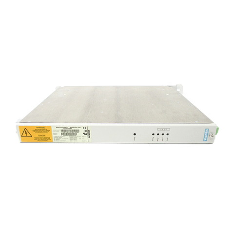
  9. Siemens SIPROTEC 5 6MU85 User manual

Siemens SIPROTEC 5 6MU85 User manual

Other Siemens Industrial Equipment manuals

Siemens 3VL9400-3AU11 User manual

Siemens

Siemens 3VL9400-3AU11 User manual

Siemens TELEPERM M AS 235 User manual

Siemens

Siemens TELEPERM M AS 235 User manual

Siemens RUGGEDCOM WIN5151-V-GPS User manual

Siemens

Siemens RUGGEDCOM WIN5151-V-GPS User manual

Siemens SIMOTICS S-1FK2 User manual

Siemens

Siemens SIMOTICS S-1FK2 User manual

Siemens VPM 120 User manual

Siemens

Siemens VPM 120 User manual

Siemens GAMMA UP 117/12 Service manual

Siemens

Siemens GAMMA UP 117/12 Service manual

Siemens SITRANS LG Series Use and care manual

Siemens

Siemens SITRANS LG Series Use and care manual

Siemens 3KX3505-0AA User manual

Siemens

Siemens 3KX3505-0AA User manual

Siemens SIMATIC NET RUGGEDCOM RX5000 Technical Document

Siemens

Siemens SIMATIC NET RUGGEDCOM RX5000 Technical Document

Siemens SIMATIC ET 200SP HA Technical Document

Siemens

Siemens SIMATIC ET 200SP HA Technical Document

Siemens SIVACON 8PS LR User manual

Siemens

Siemens SIVACON 8PS LR User manual

Siemens milltronics ZSS User manual

Siemens

Siemens milltronics ZSS User manual

Siemens SIMATIC 505 User manual

Siemens

Siemens SIMATIC 505 User manual

Siemens Simatic S7-1500/ET 200MP User manual

Siemens

Siemens Simatic S7-1500/ET 200MP User manual

Siemens EMS475S User manual

Siemens

Siemens EMS475S User manual

Siemens GCP5000 User manual

Siemens

Siemens GCP5000 User manual

Siemens SINUMERIK ONE NCU 1750 Technical Document

Siemens

Siemens SINUMERIK ONE NCU 1750 Technical Document

Siemens SIMATIC HMI OP37/Pro Technical Document

Siemens

Siemens SIMATIC HMI OP37/Pro Technical Document

Siemens 3VA9131-0QB00 User manual

Siemens

Siemens 3VA9131-0QB00 User manual

Siemens 8MF1 Series User manual

Siemens

Siemens 8MF1 Series User manual

Siemens SIMATIC S7-400H User manual

Siemens

Siemens SIMATIC S7-400H User manual

Siemens 3WN6 User manual

Siemens

Siemens 3WN6 User manual

Siemens 3TL61 User manual

Siemens

Siemens 3TL61 User manual

Siemens SIMATIC NET SCALANCE M-800 User manual

Siemens

Siemens SIMATIC NET SCALANCE M-800 User manual

Popular Industrial Equipment manuals by other brands

ABB +Q957 user manual

ABB

ABB +Q957 user manual

G.B.C BASIC EDGE 50 instruction manual

G.B.C

G.B.C BASIC EDGE 50 instruction manual

Tronair Batpak 11-6602-1000 Operation & service manual

Tronair

Tronair Batpak 11-6602-1000 Operation & service manual

Pilz PNOZ mi2p Operation manual

Pilz

Pilz PNOZ mi2p Operation manual

Clemco Zero BNP 6012 manual

Clemco

Clemco Zero BNP 6012 manual

Erskine Attachments V-Plow Operator's manual

Erskine Attachments

Erskine Attachments V-Plow Operator's manual

ABB HT610965 Operation manual

ABB

ABB HT610965 Operation manual

Morra MH 540 user manual

Morra

Morra MH 540 user manual

Eaton S090ST manual

Eaton

Eaton S090ST manual

GRIGGIO G 240 P4 instructions

GRIGGIO

GRIGGIO G 240 P4 instructions

Nexen AIR CHAMP HT45 user manual

Nexen

Nexen AIR CHAMP HT45 user manual

WTE V5 installation manual

WTE

WTE V5 installation manual

ABB HT845232 Operation manual

ABB

ABB HT845232 Operation manual

SMC Networks CJP Series Operation manual

SMC Networks

SMC Networks CJP Series Operation manual

JohnDow Industries JDI-AFT58 Operator's manual

JohnDow Industries

JohnDow Industries JDI-AFT58 Operator's manual

IMB MB9016A instruction manual

IMB

IMB MB9016A instruction manual

Clarke CUMB1 Assembly & operating instructions

Clarke

Clarke CUMB1 Assembly & operating instructions

amiad Arkal Spin Klin 2 user guide

amiad

amiad Arkal Spin Klin 2 user guide

manuals.online logo
manuals.online logoBrands
  • About & Mission
  • Contact us
  • Privacy Policy
  • Terms and Conditions

Copyright 2025 Manuals.Online. All Rights Reserved.

Technical Data
Extract from manual C53000-G5040-C074-1, chapter 12
Smart Infrastructure
SIPROTEC 5 V8.01 and higher
Merging Unit
6MU85
i
i
NOTE
For your own safety, observe the warnings and safety instructions contained in this document, if available.
Disclaimer of Liability
Subject to changes and errors. The information given in
this document only contains general descriptions and/or
performance features which may not always specifically
reflect those described, or which may undergo modifica-
tion in the course of further development of the products.
The requested performance features are binding only when
they are expressly agreed upon in the concluded contract.
Document version: C53000-G5040-C074-1.02
Edition: 01.2020
Version of the product described: V8.01 and higher
Copyright
Copyright © Siemens 2020. All rights reserved.
The disclosure, duplication, distribution and editing of this
document, or utilization and communication of the content
are not permitted, unless authorized in writing. All rights,
including rights created by patent grant or registration of a
utility model or a design, are reserved.
Trademarks
SIPROTEC™, DIGSI™, SIGRA™, SIGUARD™, SAFIR™, SICAM™,
and MindSphere™ are trademarks of Siemens. Any unau-
thorized use is prohibited. All other designations in this
document may represent trademarks whose use by third
parties for their own purposes may violate the proprietary
rights of the owner.
Preface
Purpose of the Manual
This manual describes the protection, automation, control, and monitoring functions of the SIPROTEC 5
devices.
Target Audience
Protection system engineers, commissioning engineers, persons entrusted with the setting, testing and main-
tenance of automation, selective protection and control equipment, and operational crew in electrical installa-
tions and power plants.
Scope
This manual applies to the SIPROTEC 5 device family.
Further Documentation
[dwprefdm-221012-01.tif, 3, en_US]
•Device manuals
Each Device manual describes the functions and applications of a specific SIPROTEC 5 device. The printed
manual and the online help for the device have the same informational structure.
•Hardware manual
The Hardware manual describes the hardware building blocks and device combinations of the SIPROTEC 5
device family.
•Operating manual
The Operating manual describes the basic principles and procedures for operating and assembling the
devices of the SIPROTEC 5 range.
SIPROTEC 5, Merging Unit 6MU85, Manual 3
C53000-G5040-C074-1, Edition 01.2020
•Communication protocol manual
The Communication protocol manual contains a description of the protocols for communication within
the SIPROTEC 5 device family and to higher-level network control centers.
•Product information
The Product information includes general information about device installation, technical data, limiting
values for input and output modules, and conditions when preparing for operation. This document is
provided with each SIPROTEC 5 device.
•Engineering Guide
The Engineering Guide describes the essential steps when engineering with DIGSI 5. In addition, the Engi-
neering Guide shows you how to load a planned configuration to a SIPROTEC 5 device and update the
functionality of the SIPROTEC 5 device.
•DIGSI 5 online help
The DIGSI 5 online help contains a help package for DIGSI 5 and CFC.
The help package for DIGSI 5 includes a description of the basic operation of software, the DIGSI princi-
ples and editors. The help package for CFC includes an introduction to CFC programming, basic examples
of working with CFC, and a reference chapter with all the CFC blocks available for the SIPROTEC 5 range.
•SIPROTEC 5/DIGSI 5 Tutorial
The tutorial on the DVD contains brief information about important product features, more detailed infor-
mation about the individual technical areas, as well as operating sequences with tasks based on practical
operation and a brief explanation.
•SIPROTEC 5 catalog
The SIPROTEC 5 catalog describes the system features and the devices of SIPROTEC 5.
•Selection guide for SIPROTEC and Reyrolle
The selection guide offers an overview of the device series of the Siemens protection devices, and a
device selection table.
Indication of Conformity
This product complies with the directive of the Council of the European Communities
on harmonization of the laws of the Member States concerning electromagnetic
compatibility (EMC Directive 2014/30/EU), restriction on usage of hazardous
substances in electrical and electronic equipment (RoHS Directive 2011/65/EU), and
electrical equipment for use within specified voltage limits (Low Voltage Directive
2014/35/EU).
This conformity has been proved by tests performed according to the Council Directive
in accordance with the product standard EN 60255-26 (for EMC directive), the standard
EN 50581 (for RoHS directive), and with the product standard EN 60255-27 (for Low
Voltage Directive) by Siemens.
The device is designed and manufactured for application in an industrial environment.
The product conforms with the international standards of IEC 60255 and the German
standard VDE 0435.
Standards
IEEE Std C 37.90
The technical data of the product is approved in accordance with UL.
For more information about the UL database, see ul.com
You can find the product with the UL File Number E194016.
IND. CONT. EQ.
69CA
Preface
4 SIPROTEC 5, Merging Unit 6MU85, Manual
C53000-G5040-C074-1, Edition 01.2020
Additional Support
For questions about the system, contact your Siemens sales partner.
Customer Support Center
Our Customer Support Center provides a 24-hour service.
Siemens AG
Customer Support Center
Humboldtstrasse 59
90459 Nuremberg
Germany
E-mail: [email protected]
Training Courses
Inquiries regarding individual training courses should be addressed to our Training Center:
Siemens AG Phone: +49 (911) 433-7415
Siemens Power Academy TD Fax: +49 (911) 433-7929
Humboldtstrasse 59 E-mail: [email protected]
90459 Nuremberg Internet: www.siemens.com/poweracademy
Germany
Notes on Safety
This document is not a complete index of all safety measures required for operation of the equipment (module
or device). However, it comprises important information that must be followed for personal safety, as well as
to avoid material damage. Information is highlighted and illustrated as follows according to the degree of
danger:
!
DANGER
DANGER means that death or severe injury will result if the measures specified are not taken.
²Comply with all instructions, in order to avoid death or severe injuries.
!
WARNING
WARNING means that death or severe injury may result if the measures specified are not taken.
²Comply with all instructions, in order to avoid death or severe injuries.
!
CAUTION
CAUTION means that medium-severe or slight injuries can occur if the specified measures are not taken.
²Comply with all instructions, in order to avoid moderate or minor injuries.
Preface
SIPROTEC 5, Merging Unit 6MU85, Manual 5
C53000-G5040-C074-1, Edition 01.2020
NOTICE
NOTICE means that property damage can result if the measures specified are not taken.
²Comply with all instructions, in order to avoid property damage.
i
i
NOTE
Important information about the product, product handling or a certain section of the documentation
which must be given attention.
Qualified Electrical Engineering Personnel
Only qualified electrical engineering personnel may commission and operate the equipment (module, device)
described in this document. Qualified electrical engineering personnel in the sense of this manual are people
who can demonstrate technical qualifications as electrical technicians. These persons may commission,
isolate, ground and label devices, systems and circuits according to the standards of safety engineering.
Proper Use
The equipment (device, module) may be used only for such applications as set out in the catalogs and the
technical description, and only in combination with third-party equipment recommended and approved by
Siemens.
Problem-free and safe operation of the product depends on the following:
•Proper transport
•Proper storage, setup and installation
•Proper operation and maintenance
When electrical equipment is operated, hazardous voltages are inevitably present in certain parts. If proper
action is not taken, death, severe injury or property damage can result:
•The equipment must be grounded at the grounding terminal before any connections are made.
•All circuit components connected to the power supply may be subject to dangerous voltage.
•Hazardous voltages may be present in equipment even after the supply voltage has been disconnected
(capacitors can still be charged).
•Operation of equipment with exposed current-transformer circuits is prohibited. Before disconnecting the
equipment, ensure that the current-transformer circuits are short-circuited.
•The limiting values stated in the document must not be exceeded. This must also be considered during
testing and commissioning.
Used Symbols on Device
No. Symbol Description
1 Direct current, IEC 60417, 5031
2 Alternating current, IEC 60417, 5032
3 Direct and alternating current, IEC 60417, 5033
4 Earth (ground) terminal, IEC 60417, 5017
5 Protective conductor terminal, IEC 60417, 5019
Preface
6 SIPROTEC 5, Merging Unit 6MU85, Manual
C53000-G5040-C074-1, Edition 01.2020
No. Symbol Description
6 Caution, risk of electric shock
7 Caution, risk of danger, ISO 7000, 0434
8 Protective Insulation, IEC 60417, 5172, Safety Class II devices
9 Guideline 2002/96/EC for electrical and electronic devices
10 Guideline for the Eurasian Market
Preface
SIPROTEC 5, Merging Unit 6MU85, Manual 7
C53000-G5040-C074-1, Edition 01.2020
Technical Data
12.1 General Device Data 787
12.2 Date and Time Synchronization 801
12.3 Circuit-Breaker Failure Protection 802
12.4 Circuit-Breaker Restrike Protection 804
12.5 Circuit-Breaker Supervision 805
12.6 Overcurrent Protection, Phases 806
12.7 Overcurrent Protection, Ground 816
12.8 Directional Overcurrent Protection, Phases 825
12.9 Directional Overcurrent Protection, Ground 829
12.10 Voltage Protection 833
12.11 Inrush-Current Detection 845
12.12 2nd Harmonic Detection Ground 847
12.13 External Trip Initiation 848
12.14 Automatic Reclosing 849
12.15 Current-Jump Detection 850
12.16 Voltage-Jump Detection 851
12.17 Measuring-Voltage Failure Detection 852
12.18 Voltage-Transformer Circuit Breaker 854
12.19 Voltage-Balance Supervision 855
12.20 Voltage-Sum Supervision 856
12.21 Voltage Phase-Rotation Supervision 857
12.22 Current-Balance Supervision 858
12.23 Current-Sum Supervision 859
12.24 Current Phase-Rotation Supervision 860
12.25 Temperature Supervision 861
12.26 Instantaneous Tripping at Switch onto Fault 862
12.27 Broken-Wire Detection 863
12.28 Trip-Circuit Supervision 864
12.29 Analog Channel Supervision via Fast Current Sum 865
12.30 Operational Measured Values and Statistical Values 866
12.31 Analog-Units Function Group 870
12.32 Phasor Measurement Unit 871
12.33 Measuring Transducers 872
12.34 Arc Protection 873
12
SIPROTEC 5, Merging Unit 6MU85, Manual 785
C53000-G5040-C074-1, Edition 01.2020
12.35 Synchronization Function 874
12.36 Closing-Circuit Supervision 876
12.37 Circuit-Breaker Wear Monitoring 877
12.38 CFC 878
12.39 SIPROTEC 5 Process-Bus Client 882
12.40 SIPROTEC 5 Merging Unit Functionality 883
12.41 Point-on-Wave Switching 884
Technical Data
786 SIPROTEC 5, Merging Unit 6MU85, Manual
C53000-G5040-C074-1, Edition 01.2020
General Device Data
Analog Inputs
GIS Low-Power Current Input (via Module IO240)
All current, voltage, and power data are specified as RMS values.
Rated frequency frated 50 Hz
60 Hz
Rated current Irated - 50 Hz Min. 13 mV
Max. 332 mV
Rated current Irated - 60 Hz Min. 15.4 mV
Max. 386 mV
Measuring range 50 ⋅ Irated (Protection channel)
1.6 ⋅ Irated (Metering channel)
Power consumption per current
circuit at rated current
Max. 40 mVA
Burden = 9.5 kΩ
Thermal rating Max. input voltage = 20 V
Accuracy Class 5TPE (Protection channel)
Class 0.2S (Metering channel)
Voltage Input
All current, voltage, and power data are specified as RMS values.
Rated frequency frated 50 Hz, 60 Hz
16.7 Hz (for rail devices only)
Input and output modules IO102, IO202, IO208, IO211,
IO214
IO215
Measuring range 0 V to 200 V 0 V to 7.07 V
Burden < 0.1 VA < 0.01 VA
Thermal rating 230 V continuously 20 V continuously
GIS Low-Power Voltage Input (via Module IO240)
All current, voltage, and power data are specified as RMS values.
Rated frequency frated 50 Hz
60 Hz
Rated voltage Vrated - 50 Hz Min. 0.25 mA
Max. 2.00 mA
Rated voltage Vrated - 60 Hz Min. 0.30 mA
Max. 2.20 mA
Measuring range 2 ⋅ Vrated
Power consumption per current
circuit at rated current
Max. 1 mVA
Burden = 50 Ω
Thermal rating Max. input current = 4.4 mA
Accuracy Class 0.1
Measuring-Transducer Inputs (via Module ANAI-CA-4EL)
Insulation class SELV (Safety Extra Low Voltage) (according to IEC 60255-27)
Connector type 8-pin terminal spring
12.1
12.1.1
Technical Data
12.1 General Device Data
SIPROTEC 5, Merging Unit 6MU85, Manual 787
C53000-G5040-C074-1, Edition 01.2020