Harmonic Drive SHG Series User manual


21021387 12/2018 V02
Contents
1. General .................................................................................................................................................. 4
1.1 Description of Safety Alert Symbols....................................................................................................................................5
1.2 Disclaimer and Copyright ......................................................................................................................................................5
2. Safety and Installation Instructions.................................................................................................... 6
2.1 Hazards ..................................................................................................................................................................................6
2.2 Intended Purpose ..................................................................................................................................................................7
2.3 Non Intended Purpose ..........................................................................................................................................................7
2.4 Use in Special Application Areas ......................................................................................................................................... 8
2.5 Declaration of Conformity.................................................................................................................................................... 8
2.5.1 Gears.......................................................................................................................................................................... 8
2.5.2 Servo Actuators and Motors.................................................................................................................................... 8
3. Technical Description............................................................................................................................ 9
3.1 Product Description...............................................................................................................................................................9
3.2 Ordering Code ...................................................................................................................................................................... 10
3.3 Technical Data.......................................................................................................................................................................11
3.3.1 General Technical Data .............................................................................................................................................11
3.3.2 Dimensions .............................................................................................................................................................. 12
3.3.3 Minimum Housing Dimensions SHG-2SO and SHG-2SH....................................................................................... 21
3.3.4 Accuracy ................................................................................................................................................................... 21
3.3.5 Torsional Stiness...................................................................................................................................................22
3.3.6 Bearings....................................................................................................................................................................23
3.3.7. Housing Materials and Surfaces.............................................................................................................................26
4. Actuator Selection...............................................................................................................................27
4.1 Selecting Harmonic Drive® Gears........................................................................................................................................29
4.1.1 Torque Based Dimensioning................................................................................................................................... 30
4.1.2 Life of the Wave Generator Bearing .......................................................................................................................32
4.1.3 Stiness Based Dimensioning................................................................................................................................33
4.2 Calculation of the Torsion Angle.........................................................................................................................................35
4.3 Accuracy of the Oldham Coupling SHG-2SO ......................................................................................................................35
4.4 Eciency Calculation SHG-2UH .........................................................................................................................................36
4.4.1 Eciency Calculation Scheme ................................................................................................................................36
4.4.2 Eciency Correction factor .....................................................................................................................................37
4.4.3 Eciency Correction Value......................................................................................................................................37
4.4.4 Eciency Tables ..................................................................................................................................................... 38
4.5 No Load Torque values SHG-2UH ...................................................................................................................................... 38
4.5.1 No Load Running Torque.........................................................................................................................................39
4.5.2 No Load Starting Torque ........................................................................................................................................ 40
4.5.3 No Load Back Driving Torque.................................................................................................................................. 40
4.6 Continuous Operation SHG-2UH......................................................................................................................................... 41
4.7 Output Bearing Operating Life ...........................................................................................................................................42
4.7.1 Output Bearing at Oscillating Motion.................................................................................................................... 44
4.8 Permissible Static Tilting Moment.................................................................................................................................... 45
4.9 Angle of Inclination ............................................................................................................................................................ 45
4.10 Lubrication.......................................................................................................................................................................... 46
4.10.1 Grease Lubrication.................................................................................................................................................. 46
4.10.2 Oil Lubrication......................................................................................................................................................... 48
4.11 Axial Forces at the Wave Generator SHG-2SO and SHG-2SH .......................................................................................... 49

31021387 12/2018 V02
5. Installation and Operation.................................................................................................................50
5.1 Transport and Storage........................................................................................................................................................ 50
5.2 Gear Condition at Delivery.................................................................................................................................................. 50
5.3 Assembly Information........................................................................................................................................................ 50
5.4 Recommended Tolerances for Assembly SHG-2SO and SHG-2SH ................................................................................... 51
5.5 Lubrication...........................................................................................................................................................................52
5.5.1 Grease lubrication SHG-2UH ..................................................................................................................................52
5.5.2 Grease Lubrication SHG-2SO and SHG-2SH ...........................................................................................................52
5.5.3 Additional Grease Package......................................................................................................................................53
5.5.4 Grease Change .........................................................................................................................................................53
5.5.5 Oil Lubrication......................................................................................................................................................... 54
5.6 Assembly Preparation........................................................................................................................................................ 54
5.7 Assembly of SHG-2SO and SHG-2SH Units .......................................................................................................................55
5.7.1 Motor Assembly SHG-2SO ......................................................................................................................................56
5.7.2 Wave Generator Components SHG-2SO.................................................................................................................57
5.7.3 Mounting the Wave Generator (WG) to the Motor Shaft ....................................................................................57
5.7.4 Check before Assembly of the Wave Generator (WG).......................................................................................... 58
5.7.5 Assembly of the Wave Generator (WG) into the Flexspline (FS) ........................................................................ 58
5.7.6 Assembly Control.................................................................................................................................................... 58
5.7.7 Assembly of the Output Flange..............................................................................................................................59
5.7.8 Assembly of the Housing Flange............................................................................................................................59
5.7.9 Installation of the Input Shaft SHG-2UH and SHG-2SH........................................................................................59
6. Decommissioning and Disposal.........................................................................................................60
7. Glossary................................................................................................................................................61
7.1 Technical Data ..................................................................................................................................................................... 61
7.2 Labelling, Guidelines and Regulations .............................................................................................................................. 68

41021387 12/2018 V02
1. General
About this documentation
This document contains safety instructions, technical data and operation rules for servo actuators and servo motors of
Harmonic Drive AG.
The documentation is aimed at planners, project engineers, commissioning engineers and machine manufacturers, oering
support during selection and calculation of the servo actuators, servo motors and accessories.
Rules for storage
Please keep this document for the entire life of the product, up to its disposal. Please hand over the documentation when
re-selling the product.
Additional documentation
For the configuration of drive systems using the products of Harmonic Drive AG, you may require additional documents.
Documentation is provided for all products oered by Harmonic Drive AG and can be found in pdf format on the website.
www.harmonicdrive.de
Third-party systems
Documentation for parts supplied by third party suppliers, associated with Harmonic Drive® Components, is not included in
our standard documentation and should be requested directly from the manufacturers.
Before commissioning servo actuators and servo motors from Harmonic Drive AG with servo drives, we advise you to obtain
the relevant documents for each device.
Your feedback
Your experiences are important to us. Please send suggestions and comments about the products and documentation to:
Harmonic Drive AG
Marketing and Communications
Hoenbergstraße 14
65555 Limburg / Lahn
Germany
E-Mail: info@harmonicdrive.de
51021387 12/2018 V02
1.1 Description of Safety Alert Symbols
Symbol Meaning
Indicates an imminent hazardous situation. If this is not avoided, death or
serious injury could occur.
Indicates a possible hazard. Care should be taken or death or serious injury may
result.
Indicates a possible hazard. Care should be taken or slight or minor injury
may result.
Describes a possibly harmful situation. Care should be taken to avoid damage
to the system and surroundings.
This is not a safety symbol. This symbol indicates important information.
Warning of a general hazard. The type of hazard is determined by the
specific warning text.
Warning of dangerous electrical voltage and its eects.
Beware of hot surfaces.
Beware of suspended loads.
Precautions when handling electrostatic sensitive components.
Beware of electromagnetic environmental compatibility.
1.2 Disclaimer and Copyright
The contents, images and graphics contained in this document are predected by copyright. In addition to the copyright, logos,
fonts, company and product names can also be predected by brand law or trademark law. The use of text, extracts or graphics
requires the permission of the publisher or rights holder.
We have checked the contents of this document. Since errors cannot be ruled out entirely, we do not accept liability for mis-
takes which may have occurred. Notification of any mistake or suggestions for improvements will be gratefully received and any
necessary correction will be included in subsequent editions.
DANGER
WARNING
ATTENTION
INFORMATION
ADVICE

61021387 12/2018 V02
2. Safety and Installation Instructions
Please take note of the information and instructions in this document. Specially designed models may dier in technical
detail. If in doubt, we recommend to contact the manufacturer, giving the type designation and serial number for
clarification.
2.1 Hazards
DANGER
Electric servo actuators and motors have dangerous live and rotating parts. All work during connection, operation, repair and
disposal must be carried out by qualified personnel as described in the standards EN 50110-1 and IEC 60364! Before starting
any work, and especially before opening covers, the actuator must be properly isolated. In addition to the main circuits, the
user also has to pay attention to any auxilliary circuits.
Observing the five safety rules:
• Disconnect mains
• Prevent reconnection
• Test for absence of harmful voltages
• Ground and short circuit
• Cover or close o nearby live parts
The measures taken above must only be withdrawn when the work has been completed and the device is fully assembled.
Improper handling can cause damage to persons and property. The respective national, local and factory specific regulations
must be adhered to.
ATTENTION
The surface temperature of products exceed 55 degrees Celsius. The hot surfaces should not be touched.
ADVICE
Cables must not come into direct contact with hot surfaces.
DANGER
Electric, magnetic and electromagnetic fields are dangerous, in particular for persons with heart pacemaker, implants or
similiar. Vulnerable individuals must not be in the close proximity of the product.
DANGER
Built-in holding brakes are not functional safe by themselves. Particularly with unsupported vertical axes, functional safety
can only be achieved with additional, external mechanical brakes.

71021387 12/2018 V02
DANGER
Danger of injury due to improper handling of batteries.
Observing of the battery safety rules:
• do not insert batteries in reverse. Observe the + and - marks on the battery and on the electrical device
• do not short circuit
• do not recharge
• do not open or deform
• do not expose to fire, water or high temperature
• do not leave discharged batteries in the electrical device
• keep batteries out of reach of children. In case of ingestion of a battery, seek medical assistance promptly.
WARNING
The successful and safe operation of products requires proper transport, storage and assembly as well as correct operation
and maintenance.
ATTENTION
Use suitable lifting equipment to move and lift products with a weight > 20 kg.
INFORMATION
Special versions of products may dier in the specification from the standard. Further applicable data from data sheets,
catalogues and oers of the special version have to be considered.
2.2 Intended Purpose
Harmonic Drive® Products are intended for industrial or commercial applications.
Typical areas of application are robotics and handling, machine tools, packaging and food machines and similar machines.
The products may only be operated within the operating ranges and environmental conditions shown in the documentation
(altitude, degree of predection, temperature range, etc).
Before commissioning of plants and machinery including Harmonic Drive® Products, the compliance with the Machinery
Directive must be established.
2.3 Non Intended Purpose
The use of products outside the areas of application mentioned above or beyond the operating areas or environmental
conditions described in the documentation is considered as non-intended purpose.

81021387 12/2018 V02
2.4 Use in Special Application Areas
The use of the products in one of the following application areas requires a risk assessment and approval by
Harmonic Drive AG.
• Aerospace
• Areas at risk of explosion
• Machines specially constructed or used for a nuclear purpose whose breakdown might lead to the emission of radio-activity
• Vacuum
• Household devices
• Medical equipment
• Devices which interact directly with the human body
• Machines or equipment for transporting or lifting people
• Special devices for use in annual markets or leisure parks
2.5 Declaration of Conformity
2.5.1 Gears
Harmonic Drive® Gears are components for installation in machines as defined by the Machinery Directive.
Commissioning is prohibited until the end product conforms to the provisions of this directive.
Essential health and safety requirements were considered in the design and manufacture of these gear component sets.
This simplifies the implementation of the Machinery Directive by the end user for the machinery or the partly completed
machinery. Commissioning of the machine or partly completed machine is prohibited until the end product conforms to the
Machinery Directive.
2.5.2 Servo Actuators and Motors
The Harmonic Drive® Servo Actuators and Motors described in the engineering data comply with the Low Voltage Directive.
In accordance with the Machinery Directive, Harmonic Drive® Servo Actuators and Motors are electrical equipment
for the use within certain voltage limits as covered by the Low Voltage Directive and thus excluded from the scope of the
Machinery Directive. Commissioning is prohibited until the final product conforms to the Machinery Directive.
According to the EMC directive Harmonic Drive® Servo Actuators and Motors are inherently benign equipment, unable to
generate electromagnetic disturbance or to be aected by such disturbance.
The conformity to the EU directives of equipment, plant and machinery in which Harmonic Drive® Servo Actuators and Motors
are installed must be provided by the user before taking the device into operation.
Equipment, plant and machinery with inverter driven motors must satisfy the protection requirements of the EMC directive.
It is the responsibility of the user to ensure that the installation is carried out correctly.

91021387 12/2018 V02
3. Technical Description
3.1 Product Description
The SHG-2UH Series Units are available in ten sizes with gear ratios of 50, 80, 100, 120 and 160:1 oering repeated peak
torques from 23 to 3419 Nm.
The integrated output bearing with high tilting capacity enables the direct attachment of heavy payloads without the need
for further support, ensuring a simple and space-saving design.
The SHG-2UH Unit is fully sealed with a large hollow shaft diameter to feed through supply lines, shafts or cables for further
drive systems. The gears cover a wide torque range and feature a long service life, confirmed by many years of successful
service.
The SHG-2SH and -2SO Simplicity Units are very short and lightweight. The absence of input and output flanges means ma-
ximum flexibility in design integration. The -2SH version comes with a large hollow shaft and the -2SO versions is delivered
with a standard Wave Generator.
Maximum torque capacity with largest hollow shaft

10 1021387 12/2018 V02
3.2 Ordering Code
- - -- -
Series Size Ratio1) Version Special design
SHG
14 50 80 100
2UH
2SO
2SH
According
to customer
requirements
17 50 80 100 120
20 50 80 100 120 160
25 50 80 100 120 160
32 50 80 100 120 160
40 50 80 100 120 160
45 50 80 100 120 160
50 50 80 100 120 160
58 50 80 100 120 160
65 80 100 120 160
Ordering code
SHG 25 100 2UH SP
Table 10.1
Table 10.2
- -- -
Version
Ordering code Description
2UH Unit with hollow shaft
2SO Simplicity Unit for motor assembly
2SH Simplicity Unit with hollow shaft
Clarification of the technical data can be found in the Glossary
1) The ratios shown here are for a standard driving configuration with the circular spline fixed, the Wave Generator used for the input and the Flexspline
attached to the output. Other configurations are possible. Please consult chapter 4 “Ratio”.

111021387 12/2018 V02
3.3 Technical Data
3.3.1 General Technical Data
Table 11.1
Symbol
[Unit] SHG-14
Ratio i [ ] 50 80 100
Repeated peak toque TR[Nm] 23 30 36
Average torque TA[Nm] 9.0 14 14
Rated torque TN[Nm] 7.0 10 10
Momentary peak torque TM[Nm] 46 67 70
Maximum input speed (oil lubrication) nin (max) [rpm] 14000
Maximum input speed (grease lubrication) nin (max) [rpm] 8500
Average input speed (oil lubrication) nav (max) [rpm] 6500 / 11001)
Average input speed (grease lubrication) nav (max) [rpm] 3500 / 11001)
Moment of inertia SHG-2UH Jin [· 10-4 kgm²] 0.091
Moment of inertia SHG-2SO Jin [· 10-4 kgm²] 0.033
Moment of inertia SHG-2SH Jin [· 10-4 kgm²] 0.091
Weight SHG-2UH m [kg] 0.71
Weight SHG-2SO m [kg] 0.41
Weight SHG-2SH m [kg] 0.45
1)) Valid for SHG-2UH and SHG-2SH when radial shaft seals are used on the hollow shaft.
Symbol
[Unit] SHG-17
Ratio i [ ] 50 80 100 120
Repeated peak toque TR[Nm] 44 56 70 70
Average torque TA[Nm] 34 35 51 51
Rated torque TN[Nm] 21 29 31 31
Momentary peak torque TM[Nm] 91 113 143 112
Maximum input speed (oil lubrication) nin (max) [rpm] 10000
Maximum input speed (grease lubrication) nin (max) [rpm] 7300
Average input speed (oil lubrication) nav (max) [rpm] 6500 / 11001)
Average input speed (grease lubrication) nav (max) [rpm] 3500 / 11001)
Moment of inertia SHG-2UH Jin [· 10-4 kgm²] 0.193
Moment of inertia SHG-2SO Jin [· 10-4 kgm²] 0.079
Moment of inertia SHG-2SH Jin [· 10-4 kgm²] 0.193
Weight SHG-2UH m [kg] 1.0
Weight SHG-2SO m [kg] 0.57
Weight SHG-2SH m [kg] 0.63
Table 11.2
1)) Valid for SHG-2UH and SHG-2SH when radial shaft seals are used on the hollow shaft.

12 1021387 12/2018 V02
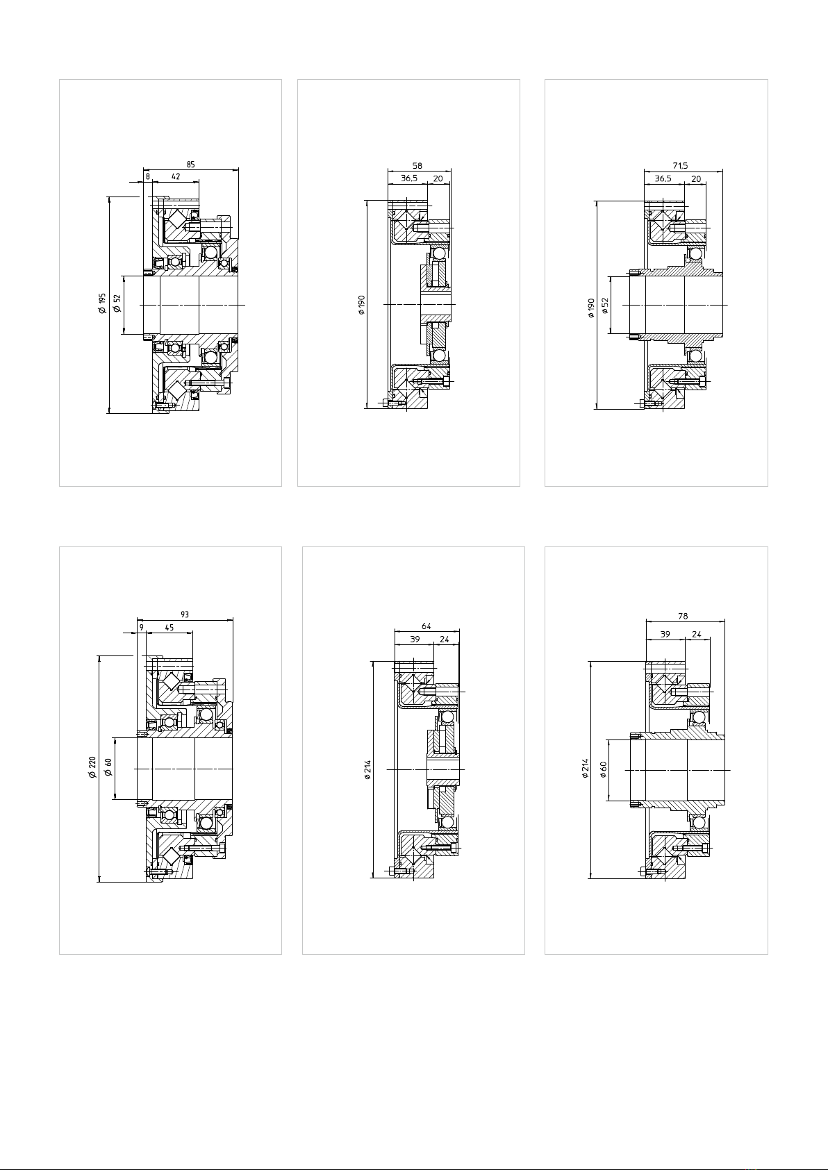
3.3.2 Dimensions
Illustration 12.1
Illustration 12.4
Illustration 12.2
Illustration 12.5
Illustration 12.3
Illustration 12.6
[mm]
[mm]
[mm]
[mm]
[mm]
[mm]
SHG-14-2UH
SHG-17-2UH
SHG-14-2SO
SHG-17-2SO
SHG-14-2SH
SHG-17-2SH

131021387 12/2018 V02
Table 13.2
Symbol
[Unit] SHG-25
Ratio i [ ] 50 80 100 120 160
Repeated peak toque TR[Nm] 127 178 204 217 229
Average torque TA[Nm] 72 113 140 140 140
Rated torque TN[Nm] 51 82 87 87 87
Momentary peak torque TM[Nm] 242 332 369 395 408
Maximum input speed (oil lubrication) nin (max) [rpm] 7500
Maximum input speed (grease lubrication) nin (max) [rpm] 5600
Average input speed (oil lubrication) nav (max) [rpm] 5600 / 10001)
Average input speed (grease lubrication) nav (max) [rpm] 3500 / 10001)
Moment of inertia SHG-2UH Jin [· 10-4 kgm²] 1.07
Moment of inertia SHG-2SO Jin [· 10-4 kgm²] 0.413
Moment of inertia SHG-2SH Jin [· 10-4 kgm²] 1.07
Weight SHG-2UH m [kg] 2.1
Weight SHG-2SO m [kg] 1.31
Weight SHG-2SH m [kg] 1.44
1)) Valid for SHG-2UH and SHG-2SH when radial shaft seals are used on the hollow shaft.
Table 13.1
Symbol
[Unit] SHG-20
Ratio i [ ] 50 80 100 120 160
Repeated peak toque TR[Nm] 73 96 107 113 120
Average torque TA[Nm] 44 61 64 64 64
Rated torque TN[Nm] 33 44 52 52 52
Momentary peak torque TM[Nm] 127 165 191 191 191
Maximum input speed (oil lubrication) nin (max) [rpm] 10000
Maximum input speed (grease lubrication) nin (max) [rpm] 6500
Average input speed (oil lubrication) nav (max) [rpm] 6500 / 11001)
Average input speed (grease lubrication) nav (max) [rpm] 3500 / 11001)
Moment of inertia SHG-2UH Jin [· 10-4 kgm²] 0.404
Moment of inertia SHG-2SO Jin [· 10-4 kgm²] 0.193
Moment of inertia SHG-2SH Jin [· 10-4 kgm²] 0.404
Weight SHG-2UH m [kg] 1.38
Weight SHG-2SO m [kg] 0.81
Weight SHG-2SH m [kg] 0.89
1)) Valid for SHG-2UH and SHG-2SH when radial shaft seals are used on the hollow shaft.

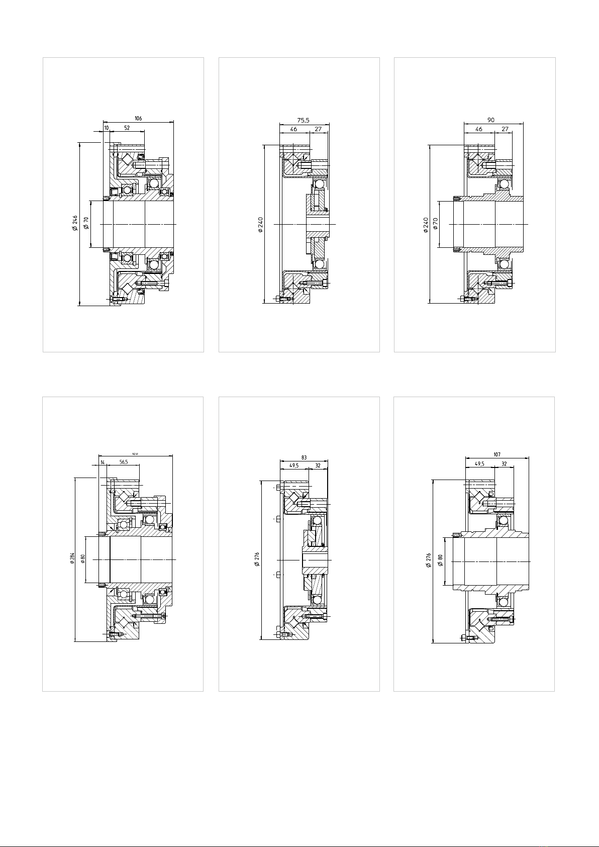
14 1021387 12/2018 V02
Illustration 14.1
Illustration 14.4
Illustration 14.2
Illustration 14.5
Illustration 14.3
Illustration 14.6
[mm]
[mm]
[mm]
[mm]
[mm]
[mm]
SHG-20-2UH
SHG-25-2UH
SHG-20-2SO
SHG-25-2SO
SHG-20-2SH
SHG-25-2SH

151021387 12/2018 V02
Table 15.1
Symbol
[Unit] SHG-32
Ratio i [ ] 50 80 100 120 160
Repeated peak toque TR[Nm] 281 395 433 459 484
Average torque TA[Nm] 140 217 281 281 281
Rated torque TN[Nm] 99 153 178 178 178
Momentary peak torque TM[Nm] 497 738 841 892 892
Maximum input speed (oil lubrication) nin (max) [rpm] 7000
Maximum input speed (grease lubrication) nin (max) [rpm] 4800
Average input speed (oil lubrication) nav (max) [rpm] 4600 / 10001)
Average input speed (grease lubrication) nav (max) [rpm] 3500 / 10001)
Moment of inertia SHG-2UH Jin [· 10-4 kgm²] 2.85
Moment of inertia SHG-2SO Jin [· 10-4 kgm²] 1.69
Moment of inertia SHG-2SH Jin [· 10-4 kgm²] 2.85
Weight SHG-2UH m [kg] 4.2
Weight SHG-2SO m [kg] 2.9
Weight SHG-2SH m [kg] 3.1
1) ) Valid for SHG-2UH and SHG-2SH when radial shaft seals are used on the hollow shaft.
Symbol
[Unit] SHG-40
Ratio i [ ] 50 80 100 120 160
Repeated peak toque TR[Nm] 523 675 738 802 841
Average torque TA[Nm] 255 369 484 586 586
Rated torque TN[Nm] 178 268 345 382 382
Momentary peak torque TM[Nm] 892 1270 1400 1530 1530
Maximum input speed (oil lubrication) nin (max) [rpm] 5600
Maximum input speed (grease lubrication) nin (max) [rpm] 4000
Average input speed (oil lubrication) nav (max) [rpm] 3600 / 9501)
Average input speed (grease lubrication) nav (max) [rpm] 3000 / 9501)
Moment of inertia SHG-2UH Jin [· 10-4 kgm²] 9.28
Moment of inertia SHG-2SO Jin [· 10-4 kgm²] 4.50
Moment of inertia SHG-2SH Jin [· 10-4 kgm²] 9.28
Weight SHG-2UH m [kg] 7.7
Weight SHG-2SO m [kg] 5.1
Weight SHG-2SH m [kg] 5.4
Table 15.2
1) Valid for SHG-2UH and SHG-2SH when radial shaft seals are used on the hollow shaft.

16 1021387 12/2018 V02
Illustration 16.1
Illustration 16.4
Illustration 16.2
Illustration 16.5
Illustration 16.3
Illustration 16.6
[mm]
[mm]
[mm]
[mm]
[mm]
[mm]
SHG-32-2UH
SHG-40-2UH
SHG-32-2SO
SHG-40-2SO
SHG-32-2SH
SHG-40-2SH

171021387 12/2018 V02
Table 17.1
Symbol
[Unit] SHG-45
Ratio i [ ] 50 80 100 120 160
Repeated peak toque TR[Nm] 650 918 982 1070 1147
Average torque TA[Nm] 345 507 650 806 819
Rated torque TN[Nm] 229 407 452 523 523
Momentary peak torque TM[Nm] 1235 1651 2041 2288 2483
Maximum input speed (oil lubrication) nin (max) [rpm] 5000
Maximum input speed (grease lubrication) nin (max) [rpm] 3800
Average input speed (oil lubrication) nav (max) [rpm] 3300 / 9001)
Average input speed (grease lubrication) nav (max) [rpm] 3000 / 9001)
Moment of inertia SHG-2UH Jin [· 10-4 kgm²] 13.8
Moment of inertia SHG-2SO Jin [· 10-4 kgm²] 8.68
Moment of inertia SHG-2SH Jin [· 10-4 kgm²] 13.8
Weight SHG-2UH m [kg] 10
Weight SHG-2SO m [kg] 6.5
Weight SHG-2SH m [kg] 6.9
1)) Valid for SHG-2UH and SHG-2SH when radial shaft seals are used on the hollow shaft.
Table 17.2
Symbol
[Unit] SHG-50
Ratio i [ ] 80 100 120 160
Repeated peak toque TR[Nm] 1223 1274 1404 1534
Average torque TA[Nm] 675 866 1057 1096
Rated torque TN[Nm] 484 611 688 688
Momentary peak torque TM[Nm] 1860 2678 2678 3185
Maximum input speed (oil lubrication) nin (max) [rpm] 4500
Maximum input speed (grease lubrication) nin (max) [rpm] 3500
Average input speed (oil lubrication) nav (max) [rpm] 3000 / 8501)
Average input speed (grease lubrication) nav (max) [rpm] 2500 / 8501)
Moment of inertia SHG-2UH Jin [· 10-4 kgm²] 25.2
Moment of inertia SHG-2SO Jin [· 10-4 kgm²] 12.5
Moment of inertia SHG-2SH Jin [· 10-4 kgm²] 25.2
Weight SHG-2UH m [kg] 14.5
Weight SHG-2SO m [kg] 9.6
Weight SHG-2SH m [kg] 10.2
1) Valid for SHG-2UH and SHG-2SH when radial shaft seals are used on the hollow shaft.
18 1021387 12/2018 V02
Illustration 18.1
Illustration 18.4
Illustration 18.2
Illustration 18.5
Illustration 18.3
Illustration 18.6
[mm]
[mm]
[mm]
[mm]
[mm]
[mm]
SHG-45-2UH
SHG-50-2UH
SHG-45-2SO
SHG-50-2SO
SHG-45-2SH
SHG-50-2SH

191021387 12/2018 V02
Table 19.1
Table 19.2
Symbol
[Unit] SHG-58
Ratio i [ ] 80 100 120 160
Repeated peak toque TR[Nm] 1924 2067 2236 2392
Average torque TA[Nm] 1001 1378 1547 1573
Rated torque TN[Nm] 714 905 969 969
Momentary peak torque TM[Nm] 3185 4134 4329 4459
Maximum input speed (oil lubrication) nin (max) [rpm] 4000
Maximum input speed (grease lubrication) nin (max) [rpm] 3000
Average input speed (oil lubrication) nav (max) [rpm] 2700 / 8001)
Average input speed (grease lubrication) nav (max) [rpm] 2200 / 8001)
Moment of inertia SHG-2UH Jin [· 10-4 kgm²] 49.5
Moment of inertia SHG-2SO Jin [· 10-4 kgm²] 27.3
Moment of inertia SHG-2SH Jin [· 10-4 kgm²] 49.5
Weight SHG-2UH m [kg] 20
Weight SHG-2SO m [kg] 13.5
Weight SHG-2SH m [kg] 14.1
Symbol
[Unit] SHG-65
Ratio i [ ] 80 100 120 160
Repeated peak toque TR[Nm] 2743 2990 3263 3419
Average torque TA[Nm] 1352 1976 2041 2041
Rated torque TN[Nm] 969 1236 1236 1236
Momentary peak torque TM[Nm] 4836 6175 6175 6175
Maximum input speed (oil lubrication) nin (max) [rpm] 3500
Maximum input speed (grease lubrication) nin (max) [rpm] 2800
Average input speed (oil lubrication) nav (max) [rpm] 2400 / 8001)
Average input speed (grease lubrication) nav (max) [rpm] 1900 / 8001)
Moment of inertia SHG-2UH Jin [· 10-4 kgm²] 94.1
Moment of inertia SHG-2SO Jin [· 10-4 kgm²] 46.8
Moment of inertia SHG-2SH Jin [· 10-4 kgm²] 94.1
Weight SHG-2UH m [kg] 28.5
Weight SHG-2SO m [kg] 19.5
Weight SHG-2SH m [kg] 20.9
1 ) Valid for SHG-2UH and SHG-2SH when radial shaft seals are used on the hollow shaft.
1) Valid for SHG-2UH and SHG-2SH when radial shaft seals are used on the hollow shaft.
20 1021387 12/2018 V02
Illustration 20.1
Illustration 20.4
Illustration 20.2
Illustration 20.5
Illustration 20.3
Illustration 20.6
[mm]
[mm]
[mm]
[mm]
[mm]
[mm]
SHG-58-2UH
SHG-65-2UH
SHG-58-2SO
SHG-65-2SO
SHG-58-2SH
SHG-65-2SH
This manual suits for next models
6
Table of contents
Other Harmonic Drive Industrial Equipment manuals


Popular Industrial Equipment manuals by other brands


Daikin
Daikin EWWD 340 Installation, operation and maintenance manual

Rohloff
Rohloff SPEEDHUB 500/14 Mounting

Innotech
Innotech INNOTECH BEF 401-10 Instructions for installation and use

Jäger
Jäger F80-M530.05 K02S5R manual

THORLABS
THORLABS DTS25 user guide

Maschinenfabrik Reinhausen
Maschinenfabrik Reinhausen VACUTAP VM-Ex operating instructions