Harmonic Drive HFUS-2A Series Dimension Guide
HFUS-2A Component Sets
Engineering Data
QUICKLINK
www.harmonicdrive.de/3050

21019658 11/2014
Contents
1. General ................................................................................................................................................. 03
1.1 Description of Safety Alert Symbols ...................................................................................................................................04
1.2 Disclaimer and Copyright .....................................................................................................................................................04
2. Safety and Installation Instructions................................................................................................... 05
2.1 Hazards .................................................................................................................................................................................05
2.2 Intended Purpose .................................................................................................................................................................06
2.3 Non Intended Purpose..........................................................................................................................................................06
2.4 Declaration of Conformity.................................................................................................................................................... 07
3. Technical Description........................................................................................................................... 08
3.1 Product Description ..............................................................................................................................................................08
3.2 Ordering Code .......................................................................................................................................................................09
3.3 Technical Data........................................................................................................................................................................10
3.3.1 General Technical Data...............................................................................................................................................10
3.3.2 Dimensions..................................................................................................................................................................11
3.3.3 Minimum Housing Clearance.....................................................................................................................................15
3.3.4 Accuracy......................................................................................................................................................................15
3.3.5 Torsional Stiness .....................................................................................................................................................15
4. Actuator Selection Procedure.............................................................................................................. 16
4.1 Selecting Harmonic Drive® Gears..........................................................................................................................................18
4.1.1 Torque Based Dimensioning......................................................................................................................................19
4.1.2 Life of the Wave Generator Bearing..........................................................................................................................21
4.1.3 Stiness Based Dimensioning................................................................................................................................. 22
4.2 Calculation of the Torsion Angle.......................................................................................................................................... 24
4.3 Accuracy of the Oldham Coupling........................................................................................................................................ 24
4.4 Eciency Versus Load ......................................................................................................................................................... 25
4.4.1 Eciency Calculations.............................................................................................................................................. 25
4.4.2 Eciency Tables........................................................................................................................................................ 26
4.5 No Load Starting-, Back Driving- and Running Torque ...................................................................................................... 29
4.5.1 No Load Running Torque .......................................................................................................................................... 29
4.5.2 No Load Starting Torque...........................................................................................................................................30
4.5.3 No Load Back Driving Torque.................................................................................................................................... 30
4.6 Lubrication .............................................................................................................................................................................31
4.6.1 Grease Lubrication .....................................................................................................................................................31
4.6.2 Oil Lubrication ........................................................................................................................................................... 33
4.7 Axial Forces at the Wave Generator .................................................................................................................................... 34
5. Installation and Operation...................................................................................................................35
5.1 Transportation and Storage ................................................................................................................................................. 35
5.2 Gear Conditions at Delivery.................................................................................................................................................. 35
5.3 Assembly Instructions.......................................................................................................................................................... 36
5.4 Recommended Tolerances for Assembly............................................................................................................................40
5.5 Wave Generator Components...............................................................................................................................................41
5.6 Bore Diameter for Solid Wave Generators ...........................................................................................................................41
5.7 Lubrication ............................................................................................................................................................................ 42
5.7.1 Grease Lubrication .................................................................................................................................................... 42
5.7.2 Grease Reservoir .......................................................................................................................................................44
5.7.3 Grease Change...........................................................................................................................................................44
5.7.4 Gears with Oil Lubrication ........................................................................................................................................ 45
5.7.5 Lubrication Holes ...................................................................................................................................................... 46
5.8 Preparation for Assembly ....................................................................................................................................................46

31019658 11/2014
5.9 Assembly............................................................................................................................................................................... 47
5.9.1 Assembly of the Circular Spline ...............................................................................................................................48
5.9.2 Assembly of the Flexspline ......................................................................................................................................48
5.9.3 Flexspline Screws...................................................................................................................................................... 49
5.9.4 Assembly of the Wave Generator to the Input Shaft.............................................................................................50
5.9.5 Check before Assembly of the Wave Generator......................................................................................................50
5.9.6 Final Check of Position of the Wave Generator....................................................................................................... 50
5.9.7 Assembly Control...................................................................................................................................................... 50
6. Glossary................................................................................................................................................. 51
6.1 Technical Data........................................................................................................................................................................51
6.2 Labelling, Guidelines and Regulations .................................................................................................................................57
1. General
About this documentation
This document contains safety instructions, technical data and operation rules for products of Harmonic Drive AG.
The documentation is aimed at planners, project engineers, commissioning engineers and machine manufacturers, oering
support during selection and calculation of the servo actuators, servo motors and accessories.
Rules for storage
Please keep this document for the entire life of the product, up to its disposal. Please hand over the documentation when
re-selling the product.
Additional documentation
For the configuration of drive systems using the products of Harmonic Drive AG, you may require additional documents.
Documentation is provided for all products oered by Harmonic Drive AG and can be found in pdf format on the website.
www.harmonicdrive.de
Third-party systems
Documentation for parts supplied by third party suppliers, associated with Harmonic Drive® components, is not included in
our standard documentation and should be requested directly from the manufacturers.
Before commissioning products from Harmonic Drive AG with servo drives, we advise you to obtain the relevant documents
for each device.
Your feedback
Your experiences are important to us. Please send suggestions and comments about the products and documentation to:
Harmonic Drive AG
Marketing and Communications
Hoenbergstraße 14
65555 Limburg / Lahn
Germany
E-Mail: info@harmonicdrive.de

41019658 11/2014
1.1 Description of Safety Alert Symbols
Symbol Meaning
Indicates an imminent hazardous situation. If this is not avoided, death or
serious injury could occur.
Indicates a possible hazard. Care should be taken or death or serious injury
may result.
Indicates a possible hazard. Care should be taken or slight or minor injury
may result.
Describes a possibly harmful situation. Care should be taken to avoid damage
to the system and surroundings.
This is not a safety symbol. This symbol indicates important information.
Warning of a general hazard. The type of hazard is determined by the
specific warning text.
Warning of dangerous electrical voltage and its eects.
Beware of hot surfaces.
Beware of suspended loads.
Precautions when handling electrostatic sensitive components.
1.2 Disclaimer and Copyright
The contents, images and graphics contained in this document are predected by copyright. In addition to the copyright, logos,
fonts, company and product names can also be predected by brand law or trademark law. The use of text, extracts or graphics
requires the permission of the publisher or rights holder.
We have checked the contents of this document. Since errors cannot be ruled out entirely, we do not accept liability for
mistakes which may have occurred. Notification of any mistake or suggestions for improvements will be gratefully received
and any necessary correction will be included in subsequent editions.
DANGER
WARNING
ATTENTION
INFORMATION
ADVICE
51019658 11/2014
2. Safety and Installation Instructions
Please take note of the information and instructions in this document. Specialy designed models may dier in technical
detail. If in doubt, we strong recommend that you contact the manufacturer, giving the type designation and serial number
for clarification.
2.1 Hazards
Electric products have dangerous live and redating parts. All work during connection, operation, repair and disposal must
be carried out by qualified personnel as described in the standards EN50110-1 and IEC 60364! Before starting any work, and
especially before opening covers, the actuator must be properly isolated. In addition to the main circuits, the user also has to
pay attention to any auxilliary circuits.
Observing the five safety rules:
• Disconnect mains
• Prevent reconnection
• Test for absence of harmful voltages
• Ground and short circuit
• Cover or close o nearby live parts
The measures taken above must only be withdrawn when the work has been completed and the device is fully assembled.
Improper handling can cause damage to persons and property. The respective national, local and factory specific regulations
must be adhered to.
Electric, magnetic and electromagnetic fields are dangerous, in particular for persons with pacemakers, implants or similiar.
Vulnerable groups must not be in the immediate vicinity of the products themselves.
Built-in holding brakes alone are not functional safe. Particularly with unsupported vertical axes, the functional safety and
security can only be achieved with additional, external mechanical brakes.
The successful and safe operation of gears, products requires proper transport, storage and assembly as well as correct
operation and maintenance.
The surface temperature of gears, motors and actuators can exceed 55 degrees Celsius. The hot surfaces should not be touched.
DANGER
DANGER
DANGER
ATTENTION
WARNING

61019658 11/2014
2.2 Intended Purpose
The Harmonic Drive® products are intended for industrial or commercial applications. They comply with the relevant parts of
the harmonised EN 60034 standards series.
Typical areas of application are robotics and handling, machine tools, packaging and food machines and similar machines.
The products may only be operated within the operating ranges and environmental conditions shown in the documentation
(altitude, degree of predection, temperature range etc).
Before plant and machinery which have Harmonic Drive® products built into them are commissioned, the compliance must be
established with the Machinery Directive, Low Voltage Directive and EMC guidelines.
Plant and machinery with inverter driven motors must satisfy the predection requirements in the EMC guidelines. It is the
responsibility of the installer to ensure that installation is undertaken correctly.
Signal and power lines must be shielded. The EMC instructions from the inverter manufacturer must be observed in order
that installation meets the EMC regulations.
2.3 Non Intended Purpose
The use of products outside the areas of application mentioned above or, inter alia, other than in the operating areas
or environmental conditions described in the documentation is considered as non-intended purpose.
The following areas of application are, inter alia, those considered as non-intended purpose:
• Aerospace
• Areas at risk of explosion
• Machines specially constructed or used for a nuclear purpose whose breakdown might lead to the emission of radio-activity
• Vacuum
• Machines for domestic use
• Medical equipment which comes into direct contact with the human body
• Machines or equipment for transporting or lifting people
• Special devices for use in annual markets or leisure parks
Movement and lifting of products with a mass > 20 Kg should only be carried out with suitable lifting gear.
Cables must not come into direct contact with hot surfaces.
Special versions of drive systems and motors may have diering specifications. Please consider all data sheet, catalogues and
oers etc. sent concerning these special versions.
ADVICE
ADVICE
ADVICE
INFORMATION

71019658 11/2014
2.4 Declaration of Conformity
Harmonic Drive® gears are components for installation in machines as defined by the machine directive 89/392/EWG.
Commissioning is prohibited until such time as the end product has been proved to conform to the provisions of this directive.
Essential health and safety requirements were considered in the design and manufacture of these gear component sets.
This simplifies the implementation of the machinery directive by the end user for the machinery or the partly completed
machinery. Commissioning of the machine or partly completed machine is prohibited until the final product conforms to
the EC Machinery Directive.

81019658 11/2014
3. Technical Description
3.1 Product Description
Compact with largest hollow shaft
HFUS-2A Series Component Sets are available in nine sizes with gear ratios of 30, 50, 80, 100, 120 and 160:1 oering
repeatable peak torques from 9 to 1840 Nm and a power density of up to 384 Nm/kg.
If required, the Component Sets are available as specific configurations tailored to your application, including special
lubricants for extended temperature ranges or special materials for extreme ambient conditions. Consisting of just
three individual components, they are very lightweight and compact.
The enlarged hollow shaft can be used to feed through supply lines, shafts or cables for further axes. Due to their
positioning accuracy stable machine properties with short cycle times are guaranteed.
-
91019658 11/2014
3.2 Ordering Code
Erläuterungen zu den technischen Daten finden Sie im Kapitel „Glossar“
Table 9.1
Table 9.2
Series Size Ratio 1) Version Special design
HFUS
14 30 50 80 100 2A-R
According to customer requirements
17 30 50 80 100 120
20 30 50 80 100 120 160
2A-GR
25 30 50 80 100 120 160
32 30 50 80 100 120 160
40 50 80 100 120 160
45 50 80 100 120 160
50 50 80 100 120 160
58 50 80 100 120 160
Ordering code
HFUS 25 100 2A-GR SP
Version
Ordering code Description
2A-R Component Set
2A-GR
1) The ratios shown here are for a standard driving configuration with the circular spline fixed, the Wave Generator used for the input and the Flexspline attached to the
output. Other configurations are possible. Please consult chapter 4 “Ratio”.

10 1019658 11/2014
3.3 Technical Data
3.3.1 General Technical Data
Table 10.1
Unit HFUS-14-2A HFUS-17-2A
Ratio i [ ] 30 50 80 100 30 50 80 100 120
Repeatable peak torque TR[Nm] 9.0 18 23 28 16 34 43 54 54
Average torque TA[Nm] 6.8 6.9 11 11 12 26 27 39 39
Rated torque TN[Nm] 4.0 5.4 7.8 7.8 8.8 16 22 24 24
Momentary peak torque TM[Nm] 17 35 47 54 30 70 87 110 86
Maximum input speed (Oil Lubrication) nin (max) [rpm] 14000 10000
Maximum input speed (Grease Lubrication) nin (max) [rpm] 8500 7300
Average input speed (Oil Lubrication) nav (max) [rpm] 6500 6500
Average input speed (Grease Lubrication) nav (max) [rpm] 3500 3500
Moment of inertia Jin [x10-4 kgm²] 0.033 0.079
Weight m [kg] 0.11 0.18
Table 10.2
Unit HFUS-20-2A HFUS-25-2A
Ratio i [ ] 30 50 80 100 120 160 30 50 80 100 120 160
Repeatable peak torque TR[Nm] 27 56 74 82 87 92 50 98 137 157 167 176
Average torque TA[Nm] 20 34 47 49 49 49 38 55 87 108 108 108
Rated torque TN[Nm] 15 25 34 40 40 40 27 39 63 67 67 67
Momentary peak torque TM[Nm] 50 98 127 147 147 147 95 186 255 284 304 314
Maximum input speed (Oil Lubrication) nin (max) [rpm] 10000 7500
Maximum input speed (Grease Lubrication) nin (max) [rpm] 6500 5600
Average input speed (Oil Lubrication) nav (max) [rpm] 6500 5600
Average input speed (Grease Lubrication) nav (max) [rpm] 3500 3500
Moment of inertia Jin [x10-4 kgm²] 0.193 0.413
Weight m [kg] 0.31 0.48
111019658 11/2014
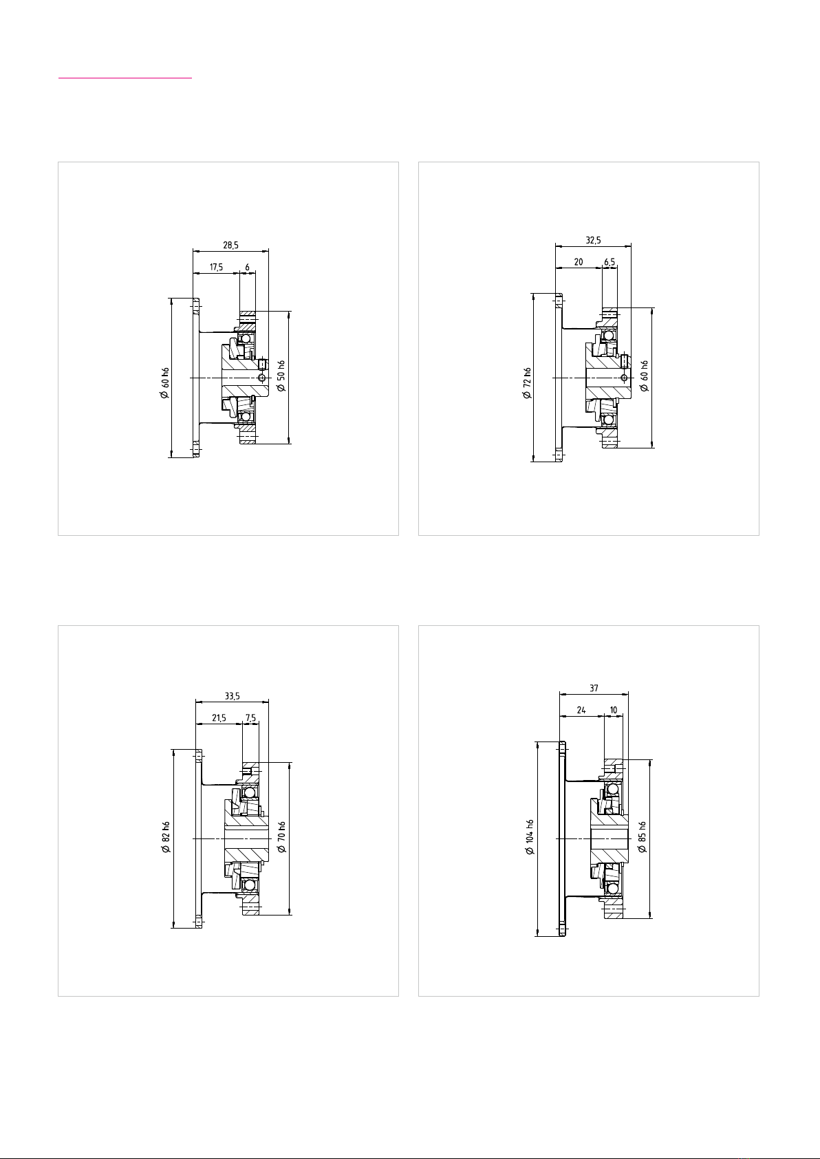
3.3.2 Dimensions
Illustration 11.1 Illustration 11.2[mm] [mm]
HFUS-14-2A HFUS-17-2A
Illustration 11.3 Illustration 11.4[mm] [mm]
HFUS-20-2A HFUS-25-2A
QUICKLINK
www.harmonicdrive.de/CAD3050

12 1019658 11/2014
Table 12.1
Unit HFUS-32-2A HFUS-40-2A
Ratio i [ ] 30 50 80 100 120 160 50 80 100 120 160
Repeatable peak torque TR[Nm] 100 216 304 333 353 372 402 519 568 617 647
Average torque TA[Nm] 75 108 167 216 216 216 196 284 372 451 451
Rated torque TN[Nm] 54 76 118 137 137 137 137 206 265 294 294
Momentary peak torque TM[Nm] 200 382 568 647 686 686 686 980 1080 1180 1180
Maximum input speed (Oil Lubrication) nin (max) [rpm] 7000 5600
Maximum input speed (Grease Lubrication) nin (max) [rpm] 4800 4000
Average input speed (Oil Lubrication) nav (max) [rpm] 4600 3600
Average input speed (Grease Lubrication) nav (max) [rpm] 3500 3000
Moment of inertia Jin [x10-4 kgm²] 1.69 4.5
Weight m [kg] 0.97 1.86
Table 12.2
Unit HFUS-45-2A HFUS-50-2A
Ratio i [ ] 50 80 100 120 160 501) 80 100 120 160
Repeatable peak torque TR[Nm] 500 706 755 823 882 715 941 980 1080 1180
Average torque TA[Nm] 265 390 500 620 630 350 519 666 813 843
Rated torque TN[Nm] 176 313 353 402 402 245 372 470 529 529
Momentary peak torque TM[Nm] 950 1270 1570 1760 1910 1430 1860 2060 2060 2450
Maximum input speed (Oil Lubrication) nin (max) [rpm] 5000 4500
Maximum input speed (Grease Lubrication) nin (max) [rpm] 3800 3500
Average input speed (Oil Lubrication) nav (max) [rpm] 3300 3000
Average input speed (Grease Lubrication) nav (max) [rpm] 3000 2500
Moment of inertia Jin [x10-4 kgm²] 8.68 12.5
Weight m [kg] 2.64 3.53
1) Only with oil lubrication. Grease lubrication is possible if the average torque Tav does not exceed half the rated torque TN.
131019658 11/2014
Illustration 13.1 Illustration 13.2[mm] [mm]
HFUS-32-2A HFUS-40-2A
Illustration 13.3 Illustration 13.4[mm] [mm]
HFUS-45-2A HFUS-50-2A
QUICKLINK
www.harmonicdrive.de/CAD3050
14 1019658 11/2014
1) Only with oil lubrication. Grease lubrication is possible if the average torque Tav does not exceed half the rated torque TN.
Table 14.1
Unit HFUS-58-2A
Ratio i [ ] 501) 80 100 120 160
Repeatable peak torque TR[Nm] 1020 1480 1590 1720 1840
Average torque TA[Nm] 520 770 1060 1190 1210
Rated torque TN[Nm] 353 549 696 745 745
Momentary peak torque TM[Nm] 1960 2450 3180 3330 3430
Maximum input speed (Oil Lubrication) nin (max) [rpm] 4000
Maximum input speed (Grease Lubrication) nin (max) [rpm] 3000
Average input speed (Oil Lubrication) nav (max) [rpm] 2700
Average input speed (Grease Lubrication) nav (max) [rpm] 2200
Moment of inertia Jin [x10-4 kgm²] 27.3
Weight m [kg] 5.17
Illustration 14.2 HFUS-58-2A [mm]
QUICKLINK
www.harmonicdrive.de/CAD3050

151019658 11/2014
3.3.5 Torsional Stiness
Table 15.4
3.3.3 Minimum Housing Clearance
Table 15.1
Illustration 15.2
[mm]
3.3.4 Accuracy
Size 14 17 ≥20
Ratio 30 ≥50 30 ≥50 30 ≥50
Transmission accuracy 1) <2 <1.5 <1.5 <1.5 <1.5 <1
Hysteresis loss <3 <1 <3 <1 <3 <1
Lost Motion <1
Repeatability < ± 0.1
1) Higher precision on request
Table 15.3 [arcmin]
Size 14 17 20 25 32 40 45 50 58
u 1.7 2.1 2.0 2.0 2.0 2.0 2.3 2.5 2.9
ØW 31 38 45 56 73 90 101 113 131
x 24.5 27.5 30.5 35.5 43.5 53.0 59.0 65.0 75.5
y 2.9 3.6 3.7 4.2 4.8 5.4 6.1 6.8 7.9
ØZ 38 45 53 66 86 106 119 133 154
Size 14 17 20 25 32 40 45 50 58
T1[Nm] 2 3.9 7 14 29 54 76 108 168
T2[Nm] 6.9 12 25 48 108 196 275 382 598
i = 30
K3[x10³ Nm/rad] 3.4 6.7 11 21 49 – – – –
K2[x10³ Nm/rad] 2.4 4.4 7.1 13 30 – – – –
K1[x10³ Nm/rad] 1.9 3.4 5.7 10 24 – – – –
i = 50
K3[x10³ Nm/rad] 5.7 13 23 44 98 180 260 340 540
K2[x10³ Nm/rad] 4.7 11 18 34 78 140 200 280 440
K1[x10³ Nm/rad] 3.4 8.1 13 25 54 100 150 200 310
i > 50
K3[x10³ Nm/rad] 7.1 16 29 57 12 230 330 440 710
K2[x10³ Nm/rad] 6.1 14 25 50 11 200 290 400 61 0
K1[x10³ Nm/rad] 4.7 10 16 31 67 130 180 250 400

16 1019658 11/2014
4. Driving Arrangements
A variety of dierent driving arrangements are possible with Harmonic Drive® gears.
Overview Harmonic Drive® Products
The three main components of the Harmonic Drive® units, Circular Spline (CS), Flexspline (FS) and Wave Generator (WG) can
be seen in the illustration 16.2.
Ratio i = Input speed
Output speed
Equation 16.1
Illustration 16.2
The values for ratios of Harmonic Drive® gears refer to the standard input and output arrangement (example 1 in the table
below). Other arrangements are possible, and also shown in the table.

171019658 11/2014
FS WG
CS
Ratio = -
Reduction gearing
CS Fixed
WG Input
FS Output
Reduction gearing
FS Fixed
WG Input
CS Output
Reduction gearing
WG Fixed
FS Input
CS Output
Dierential gear
WG Control input
CS Main drive input
FS Main drive output
Numerous dierential functions can be obtained by combinations of the speed and rotational direction of the three basic elements.
Please refer to our broshure “Dierential Applications” available to download from our website.
Input and output rotate in opposite directions. Input and output rotate in same direction. Input and output rotate in same direction.
Equation 17.1
Equation 17.4
1) 2) 3)
Equation 17.2
Equation 17.5
Equation 17.3
Equation 17.6
Speed increaser gearing
WG Fixed
CS Input
FS Output
Speed increaser gearing
CS Fixed
FS Input
WG Output
Speed increaser gearing
FS Fixed
CS Input
WG Output
Input and output rotate in same direction. Input and output rotate in opposite directions. Input and output rotate in same direction.
4) 5) 6)
7)
Ratio
i
1Ratio = i+1
1Ratio= i +1
1
Ratio = i
i+1 Ratio = -1
i Ratio = 1
i+1

18 1019658 11/2014
4.1 Selecting Harmonic Drive® Gears
When choosing a gear, both torque as well as stiness requirements should be take into account. In robot applications, for
example, the necessary torque is the more crucial factor for the gear size, while the torsional stiness is often decisive in
machine tool applications. We therefore recommend that you always take both criteria into account according to the following
procedures.
Gear preselection
Application
Gear size
sucient?
Gear size
sucient?
Selection of a
bigger size
Yes
Yes
No
No
Selection of a
bigger size
End of gear
selection
Torque based dimensioning
according to selection
procedure on page 19
Stiness based dimensioning
according to selection
procedure on page 22

191019658 11/2014
4.1.1 Torque Based Dimensioning
Output Data
Time
n1
n2
t2
T2
t3
np
tpt1
T1
n1
n3
t1
T1
Torque Speed
T3
Torques T1...Tn[Nm]
during the load phases t1...tn[s]
during the pause time tp[s]
and output speeds n1...nn[rpm]
Emergency stop/momentary peak torque Tk[Nm]
at output speed nk[rpm]
and duration tk[s]
Equation 19.2
Illustration 19.1
Permissible maximum input speed
nin max = nout max · i ≤Maximum input speed (see rating table)
Load limit 2, TR
Tmax ≤ TR
Operating life
L50 = Ln*· Rated input speed ·(Rated torque TN)3
nin av Tav
nout av =
|n1|· t1+ |n2|· t2+ ... + |nn|· tn
t1+ t2+ ... + tn+ tp
Equation 19.4
Equation 19.6
Equation 19.8
Equation 19.11
Equation 19.9 Equation 19.10
Equation 19.5
Equation 19.7
Selection of a bigger size
No
Equation 19.3
Load limit 3, TM
Tk≤ TM
Allowable number of momentary peak torques
Nk max = 104
2· nk ·i·tk
60
Permissible average input speed
nin av ≤ Limit for average input speed
(see rating table)
Values for TAsee rating tables
Tav ≤ TA
Calculation of the average output speed
Load limit 1,
Calculation of the average output torque Tav
3 |n1· T13| · t1+|n2· T23| · t2+ ... + |nn· Tn3 |· tn
|n1| · t1+|n2|·t2+ ... + |nn|· tn
Tav =
Average input speed
nin av = i · nout av
< 104
Values for Lnsee table 21.1
Time

20 1019658 11/2014
Output Data
T1= 400 Nm t1= 0.3 s n1= 7 rpm
T2= 320 Nm t2= 3.0 s n2= 14 rpm
T3= 200 Nm t3= 0.4 s n3= 7 rpm
Tk=500 Nm tk= 0.15 s nk=14 rpm
tp= 0.2 s np=0 rpm
Ratio i = 120
Life L50 = 30000 h (required)
Load limit 1,
calculation of the average output torque Tav
Tav = 319 Nm ≤TA= 451 Nm Selected size
HFUC-40-120-2A-GR
Calculation of the average
output speed Average input speed
nin av = 120 · 12.0 rpm = 1440 rpm
nout av =7 rpm · 0.3 s + 14 rpm · 3 s + 7 rpm · 0.4 s =12.0 rpm
0.3 s + 3 s + 0.4 s + 0.2 s
Permissible maximum input speed
nin max = 14 rpm · 120 = 1680 rpm ≤4000 rpm
Permissible average input speed
nin av = 1440 rpm ≤3000 rpm
Load limit 2, TRLoad limit 3, TM
Allowable number of
momentary peak torques
Tmax = 400 Nm ≤TR= 617 Nm Tk= 500 Nm ≤TM= 1180 Nm
104
14 · 120
2 · 60 · 0.15
Operating life
HFUC-40-120-2A-GR: L50 = 35000 h · 2000 rpm ·(294 Nm )3
1440 rpm 319 Nm L50 = 38054 h > 30000 h
3 7 rpm · (400 Nm)3 · 0.3 s + 14 rpm · (320 Nm)3 ·3 s + 7 rpm · (200 Nm)3 · 0.4 s
7 rpm · 0.3 s + 14 rpm · 3 s + 7 rpm · 0.4 s
Tav =
Nk max = = 1190 < 104
This manual suits for next models
9
Table of contents
Other Harmonic Drive Industrial Equipment manuals


Popular Industrial Equipment manuals by other brands


Schrempp electronic
Schrempp electronic MG-1-T2-IOL M8 manual

Festo
Festo DACS S Series instructions

PCB
PCB M1630-04C Installation and operating manual

TSCHAN
TSCHAN TORMAX VSG Installation and operation manual

TLV
TLV Free Float S3-E instruction manual

Rodix
Rodix FEEDER CUBE FC-40 Plus Series Adjustments and Set Up