Harris TE-3 User manual

L
.. . .
,
r
c
“...
:i
I c::I
I,
.

TECHNICAL MANUAL
THIS TECHNICAL MANUALPROVIDES THE NECESSARY
INFORMATIONFOR THE APPLICATIQN, INSTALLATION,
OPERATION, ADJUSTMENTAND MAINTENANCEOF THE
TE-3 EXCITER.
HARRIS~ CORPORATION
Broadcas; Products Division
T.M. No. 888 1042 001
--__-- - ~___
,
,
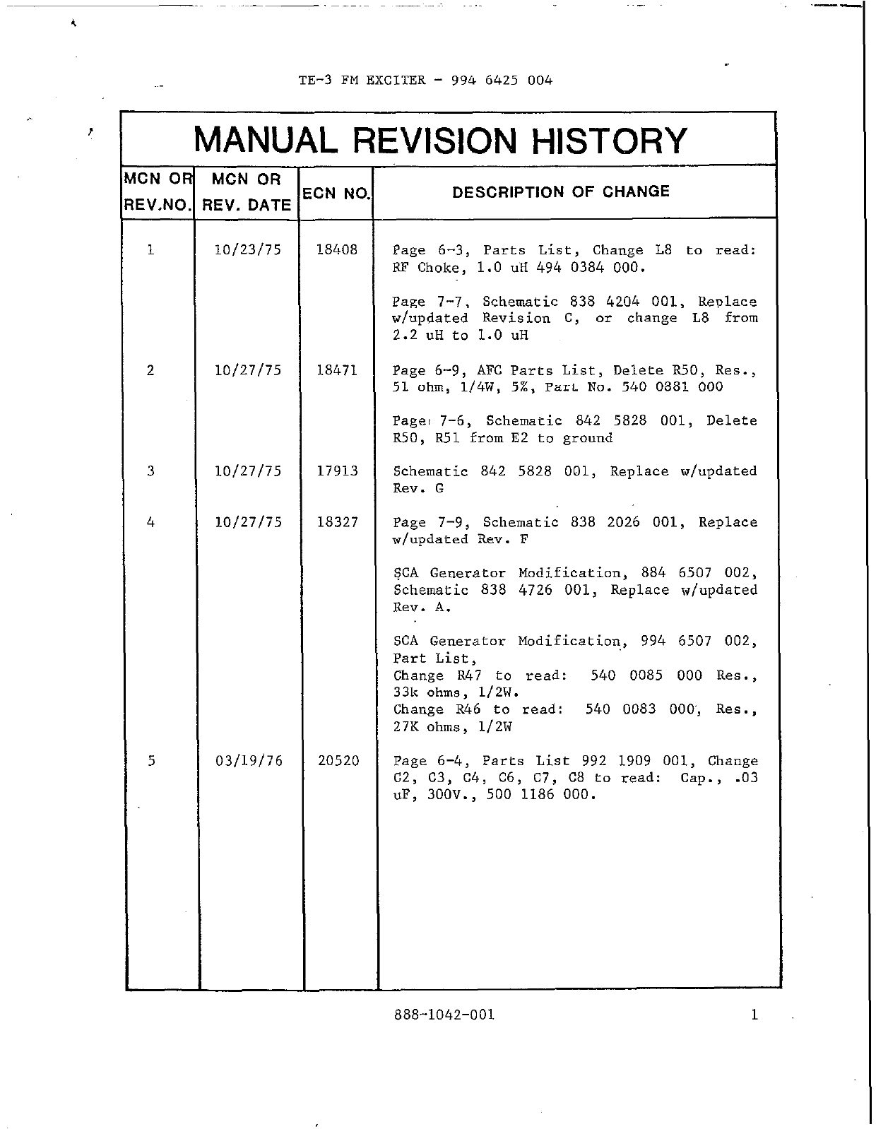
. TE-3 FM EXCITER - 994 6425 004
MANUAL REVISION HISTORY
CN OR MCN OR
IV.NO. REV. DATE ECN NO. DESCRIPTION OF CHANGE
1
10/23/75 18408 Page 6-3, Parts List, Change L8 to read:
RF Choke, 1.0 uH 494 0384 000.
Page 7-7, Schematic 838 4204 001, Replace
w/updated Revision C, or change L8 from
2.2 uH to 1.0 uH
10/27/75 18471 Page 6-9, AFC Parts List, Delete R50, Res.,
51 ohm, 1/4W, 5%, Part No. 540 0881 000
Pager 7-6, Schematic 842 5828 001, Delete
R50, R51 from E2 to ground
10127175 17913 Schematic 842 5828 001, Replace w/updated
Rev. G
4
10/27/75
18327 Page
J-9,
Schematic 838 2026 001, Replace
w/updated Rev. F
SCA Generator Modification, 884 6507 002,
Schematic 838 4726 001, Replace w/updated
Rev. A.
SCA Generator Modification, 994 6507 002,
Part List,
5
Change
R47
to read: 540 0085 000 Res.,
33k ohms, 1/2W.
Change R46 to read: 540 0083 OOO', Res.,
27X ohms, 1/2W
03/19/76
20520 Page 6-4, Parts List 992 1909 001, Change
C2, C3, C4, C6,
CJ, CS
to read: cap., .03
uF, 3OOV., 500 1186 000.
888-1042-001 1
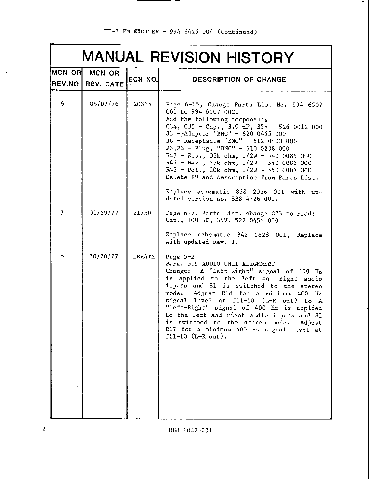
TE-3 FM EXCITER - 994 6425 004 (Continued)
MANUAL REVISION HISTORY
ICN OR MCN OR ECN NO.
IEV.NO. REV. DATE DESCRIPTION OF CHANGE
6 04/07/76 20365 Page 6-15, Change Parts List No. 994 6507
001 to 994 6507 002.
Add the following components:
c34, c35 - cap., 3.9 uF, 35V - 526 0012 000
53 -:Adaptor "BNC" - 620 0455 000
J6 - Receptacle "BNC" - 612 0403 000
P3,P6 - Plug, "BNC" - 610 0238 000
R47 - Res., 33k ohm, 1/2W - 540 0085 000
R46 - Res., 27k ohm, 1/2W - 540 0083 000
R48 - Pot., 10k ohm, 1/2W - 550 0007 000
Delete R9 and description from Parts List.
Replace schematic 838 2026 001 with up-
dated version no. 838 4726 001.
7 01/29/77 21750 Page 6-7, Parts List, change C23 to read:
Cap., 100 uF, 35V, 522 0454 000
Replace schematic 842 5828 001, Replace
with updated Rev. 3.
8 10/20/77 ERRATA Page 5-2
Para. 5.9 AUDIO UNIT ALIGNMENT
Change: A "Left-Right" signal of 400 Hz
is applied to the left and right audio
inputs and Sl is switched to the stereo
mode. Adjust R18 for a minimum 400 Hz
signal level at 511-10 (L-R out) to A
"left-Right" signal of 400 Hz is applied
to the left and right audio inputs and Sl
is switched to the stereo mode. Adjust
R17 for a minimum 400 Hz signal level at
Jll-10 (L-R out).
2 888-1042-001

TE-3 FM EXCITER - 994 6425 004 (Continued)
WWJAL REVISION HISTORY
ICN OR MCN OR ECN NO.
EV.NO. REV. DATE DESCRIPTION OF CHANGE
Change: A "Left-Minus Right" signal of
400 Hz is then connected into the left and
right audio inputs. Switch Sl to the
stereo mode position and adjust R17 for a
minimum 400 Hz signal level at 511-6 (L+R
out):to A "Left-Minus Right" signal of 400
Hz is then connected into the left and
right audio inputs. Switch Sl to the
stereo mode position and adjust Rl8 for
minimum 400 Hz signal level at 511-6 (L+R
out).'
9 09/30/81 26057 Page 6-10, Table 6.8
Change Rl from Res 300 ohm 7W, 546 0229
000 to
Res.
300 ohm low, 5%, NOI3
Inductive, 544 1633 000. R3 still retains
same description "Same as Rl".
888-1042-001 3
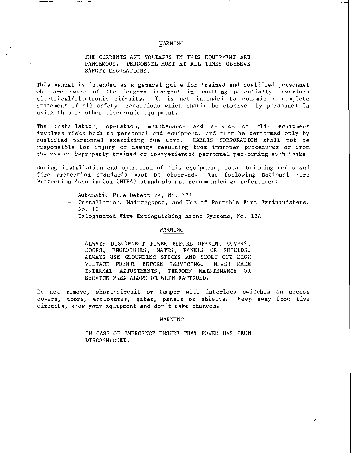
WARNING
THE CURRENTSAND VOLTAGES IN THIS EQUIPMENT ARE
DANGEROUS. PERSONNELMUST AT ALL TIMES OBSERVE
SAFETY REGULATIONS.
This manual is intended as a general guide for trained and qualified personnel
who are aware of the dangers inherent in handling potentially hazardous
electrical/electronic circuits. It is not intended to contain a complete
statement of all safety precautions which should be observed by personnel in
using this or other electronic equipment.
The installation, operation, maintenance and service of this equipment
involves risks both
to
personnel and eduipment, and must be performed only by
qualified personnel exercising due care. HARRIS CORPORATION shall not be
responsible for injury or damage resulting from improper procedures or from
the use of improperly trained or inexperienced personnel performing such tasks.
During installation and operation of this equipment, local building codes and
fire protection standards must be observed. The following National Fire
Protection Association (NFPA) standards are recormnended as references:
- Automatic Fire Detectors,
No.
72E
- Installation, Maintenance, and Use of Portable Fire Extinguishers,
No. 10
- Halogenated Fire Extinguishing Agent Systems, No. 12A
WARNING
ALWAYS DISCONNECT POWERBEFORE OPENING COVERS,
DOORS, ENCMSURES, GATES, PANELS OR SHIELDS.
ALWAYS USE GROUNDING STICKS AND SHORT OUT HIGH
VOLTAGE POINTS BEFORE SERVICING. NEVER MAKE
INTERNAL ADJUSTMENTS, PERFORM MAINTENANCE OR
SERVICE WHENALONE OR WHENFATIGUED.
Do not remove, short-circuit or tamper with interlock switches on access
covers, doors, enclosures, gates, panels or shields. Keep away from live
circuits, know your equipment and don't take chances.
WARNING
IN CASE OF EMERGENCYENSURE THAT POWERHAS BEEN
DISCONNECTED.

Treatment of
Electrical
Shock
1. If
victim is
not responsive follow the A-B-& of basic life support.
PLACE VICTIM FLAT ON HIS BACK ON A HARD SURFACE
0
A AIRWAY
IF
UNCONSCIOUS.
OPENAIRWAY
LIFT UP NECK
PUSH FOREHEAD BACK
CLEAR OUT MOUTH IF NECESSARY
OBSERVE FOR BREATHING
0
B BREATHING
IF NOT BREATHING,
BEGIN ARTIFICIAL
BREATHING
TILT HEAD
PINCH NOSTRILS
MAKE AIRTIGHT SEAL
4 BUICK FULL BREATHS
REMEMBER MOUTH TO MOUTH RESUSCITATION
MUST BE COMMENCDJ As SOON As POSSIBLE
CHECK CAROTID PULSE
ON
1/2”TO 2”
APPROX.
8. SEC. 15 COMPRESSIONS
C
ONE RESCUER
2 BUICK BREATHS
APPROX. TWO RESCUERS
60 SEC.i 5 COMPRESSIONS
1 BREATH
NOTE: DO NOT INTERRUPT RHYTHM OF COMPRESSIONS
WHEN SECOND PERSON IS GIVING BREATH
Call for medical assistance as soon as possible.
2. If
victim is
responsive.
a. keep them warm
b. keep them as quiet as possible
C. loosen their clothing
(a reclining position is recommended)
ii
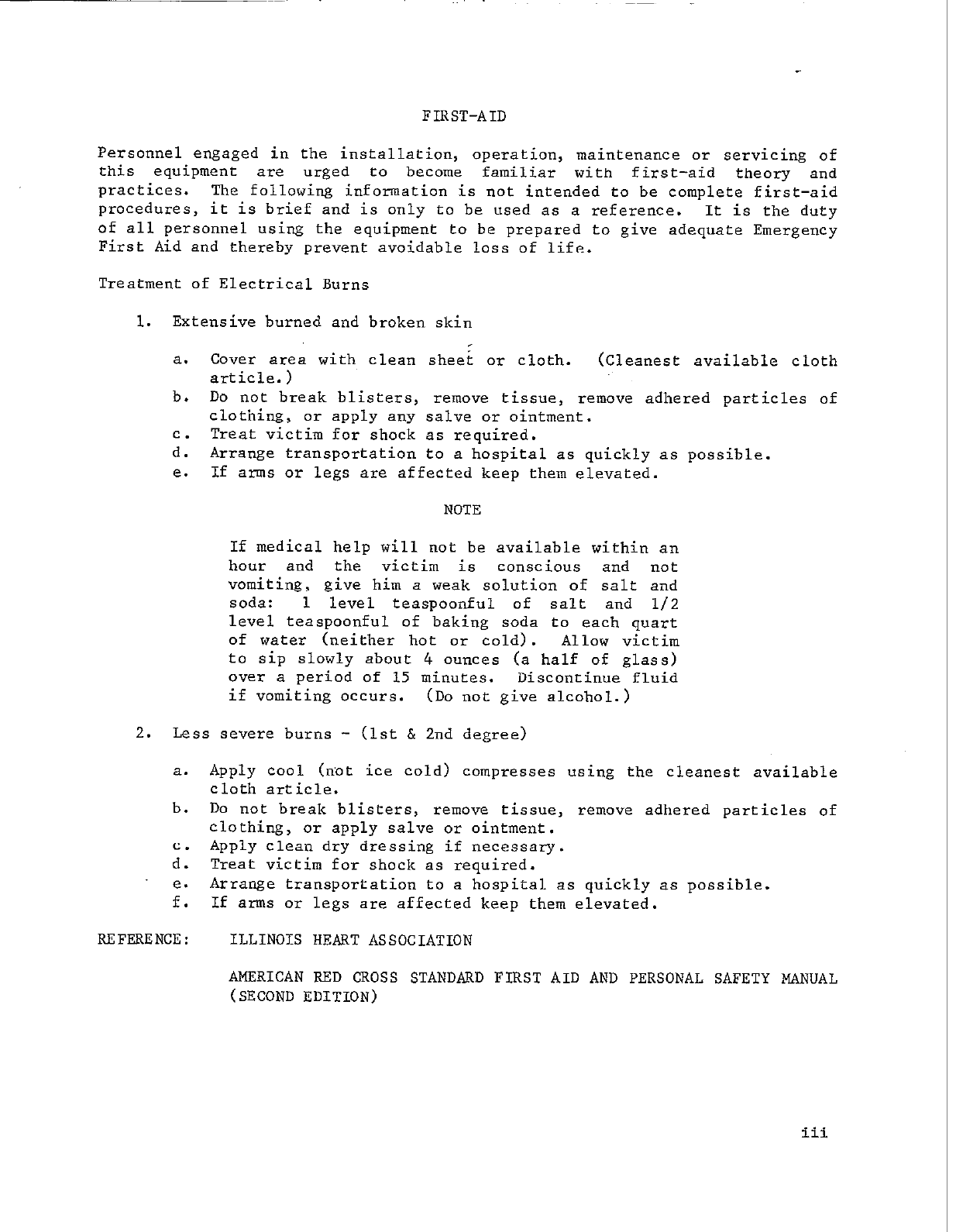
FIRST-AID
Personnel engaged in the installation, operation, maintenance or servicing of
this equipment are urged to become familiar with first-aid theory and
practices. The following information is not intended to be complete first-aid
procedures, it is brief and is only to be used as a reference. It is the duty
of all personnel using the equipment to be prepared to give adequate Emergency
First Aid and thereby prevent avoidable loss of life.
Treatment of Electrical Burns
1. Extensive burned and broken skin
a. Cover area with clean shei or cloth. (Cleanest available cloth
article.)
b. Do not break blisters, remove tissue, remove adhered particles of
clothing, or apply any salve or ointment.
C. Treat victim for shock as required.
d. Arrange transportation to a hospital as quickly as possible.
e. If arms or legs are affected keep them elevated.
NOTE
If medical help will not be available within an
hour and the victim is conscious and not
vomiting, give him a weak solution of salt and
soda: 1 level teaspoonful of salt and l/2
level teaspoonful of baking soda to each quart
of water (neither hot or cold). Allow victim
to sip slowly about 4 ounces (a half of glass)
over a period of 15 minutes. Discontinue fluid
if vomiting occurs. (Do not give alcohol.)
2. Less severe burns - (1st & 2nd degree)
a. Apply cool (not ice cold) compresses using the cleanest available
cloth article.
b. Do not break blisters, remove tissue, remove adhered particles of
clothing, or apply salve or ointment.
C. Apply clean dry dressing if necessary.
d. Treat victim for shock as required.
e. Arrange transportation to a hospital as quickly as possible.
f. If arms or legs are affected keep them elevated.
REFERENCE: ILLINOIS HEART ASSOCIATION
AMERICAN RED CROSS STANDARDFIRST AID AND PERSONAL SAFETY MANUAL
(SECOND EDITION)
iii

TABLE OF CONTENTS
SECTION PAGE
FRONTISPIECE ................................................................................
INTRODUCTORY INFORMATION .................................................. ii
TABLE OF CONTENTS ..................................................................... iii
1
1.1
1.2
1.3
2
2.1
2.2
2.3
2.4
2.5
2.6
2.7
3
3.1
3.2
3.3
3.4
3.5
4
4.1
4.2
4.3
4.4
4.5
4.6
4.7
4.8
DESCRIPTION ..................................................................... .............. l-3
GENERAL.. .......................................................................... ... ........ 1-l
OPTIONAL EQUIPMENT’. ................................................................. l-1
TECHNICAL CHARACTERISTICS .............. ..................................... 1-I
Fig. 1.1 Front View ............................................................. 1-4
Fig. 1.2 Front View ............................................................. 1-5
Fig. 1.3 Front View ............................................................. 1-6
INSTALLATION ................................................................................ 2-1
DAMAGE CLAIM INFORMATION. ................................................... 2-l
UNPACKING AND INSPECTION ...................................................... 2-1
UNPACKING CHECK LIST.. .............................................................. 2-1
MECHANICAL DETAILS.. ................................................................ 2-I
POWER REQUIREMENTS&CONNECTION .................................... 2-I
RF OUTPUT CONNECTION.. ............................................................ 2-2
ADDITIONAL CONNECTIONS.. ....................................................... 2-2
Fig. 2.1 Rear View ............................................................... 2-3
OPERATION AND ADJUSTMENT.. .................................................. 3-1
FRONT PANEL CONTROLS ............................................................ 3-1
Table 3.1 Fuse and Test Point Location .................. ........... :., 3-1
TURN-ON PROCEDURE.. ................................................................. 3-2
MODULATED 0~1 LLATOR ADJUSTMENT ................................... 3-2
ALARM CIRCUITS ADJUSTMENT .................................................. 3-2
~+FC. MULTIMETER.. ........................ ............................ .
.................... 3-3
THEORY OF OPERATION .............................................................. . 4-l
GENERAL ......................................................................................... 4-1
POWER SUPPLY.. .............................................................................. 4-1
POWER AMPLIFIER ......................................................................... 4-1
AUDIO UNIT.. ................................................................................... 4-1
MODULATED OSCILLATOR.. .......................................................... 4-2
AUTOMATIC FREQUENCY CONTROL UNIT ................................ 4.4
STEREO GENERATOR .................................................................... 4-6
SUB-CARRIER GENERATOR ..........................................................
4-J
iv

SECTION PAGE
Fig. 4.1 Internal View Power Supply ................................... 4-9
Fig. 4.2 Power Amplifier ..................................................... 4-10
Fig. 4.3 Internal View Modulated Oscillator.. ...................... 4-1 1
Fig. 4.4 internal View AFC Unit ......................................... 4-12
Fig. 4.5 Internal View Audio Unit ..................................... 4-13
Fig. 4.6 Internal View Stereo Gerlerator ............................ 4-14
Fig. 4.7 Internal View SCA Generator ................................ 4-15
TROUBLESHOOTING ...................................................................... 5-1
5
5.1
5.2
5.3
5.4
5.5
5.6
5.7
5.8
5.9
5.10
5.1 1
6
6.1
6.2
6.3
6.4
6.5
6.6
6.7
6.8
6.9
6.10
CHASSIS.. ..........................................................................................
POWER SUPPLY ................................................................................
10 W POWER AMPLIFIER ................................................................
AUDIO UNIT .....................................................................................
MODULATED OSCILLATOR ............................................................
AFC UNIT.. ........................................................................................
FILTER ASSEMBLY ..........................................................................
ISOLATION PAD, 3 dB .............................................................. :......
STEREO GENERATOR.. ...................................................................
SCA GENERATOR ............................................................................
6-1
6-I
6-3
6-4
6-5
6-7
6-10
6-10
6-1 1
6-15
7 DRAWINGS ..............................................................._........................ 7-1
GENERAL ...................... ....................................................................
NO CARRIER OUTPUT ....................................................................
CARRIER OFF FREQUENCY ..........................................................
HIGH DISTORTION ..........................................................................
HIGH NOISE.. ....................................................................................
EXCESSIVE CROSSTALK ................................................................
POOR STEREO SEPARATION .........................................................
POWER AMPLIFIER TUNING ................................................ ..........
AUDIO UNIT ALIGNMENT ..............................................................
STEREO GENERATOR ALIGNMENT ..............................................
SUB-CARRIER GENERATOR SETTING ..........................................
5-I
5-1
5-1
5-l
5-2
5-2
5-2
5-2
5-2
5-3
5-3
PARTS LIST ...................................................................................... 6-1
Fig. 7.1
Fig. 7.2
Fig. 7.3
Fig. 7.4
Fig. 7.5
Fig. 7.6
Fig. 7.7
Fig. 7.8
Fig. 7.9
Fig.
7.10
Block Diagram ........................................................
interconnecting Diagram ........................................
Power Supply .........................................................
Modulated Oscillator ...............................................
AFC Unit.. ..............................................................
10 W Amplifier .......................................................
Audio Unit ......... ....................................................
SCA Generator.. ......................................................
Stereo Generator.. ...................................................
AT-1 Isolation Pad .....................
7-2
7-3
7-4
7-5
7-6
7-7
7-8
7-9
7-10
7-11
v/vi
SECTION 1 -DESCRIPTION
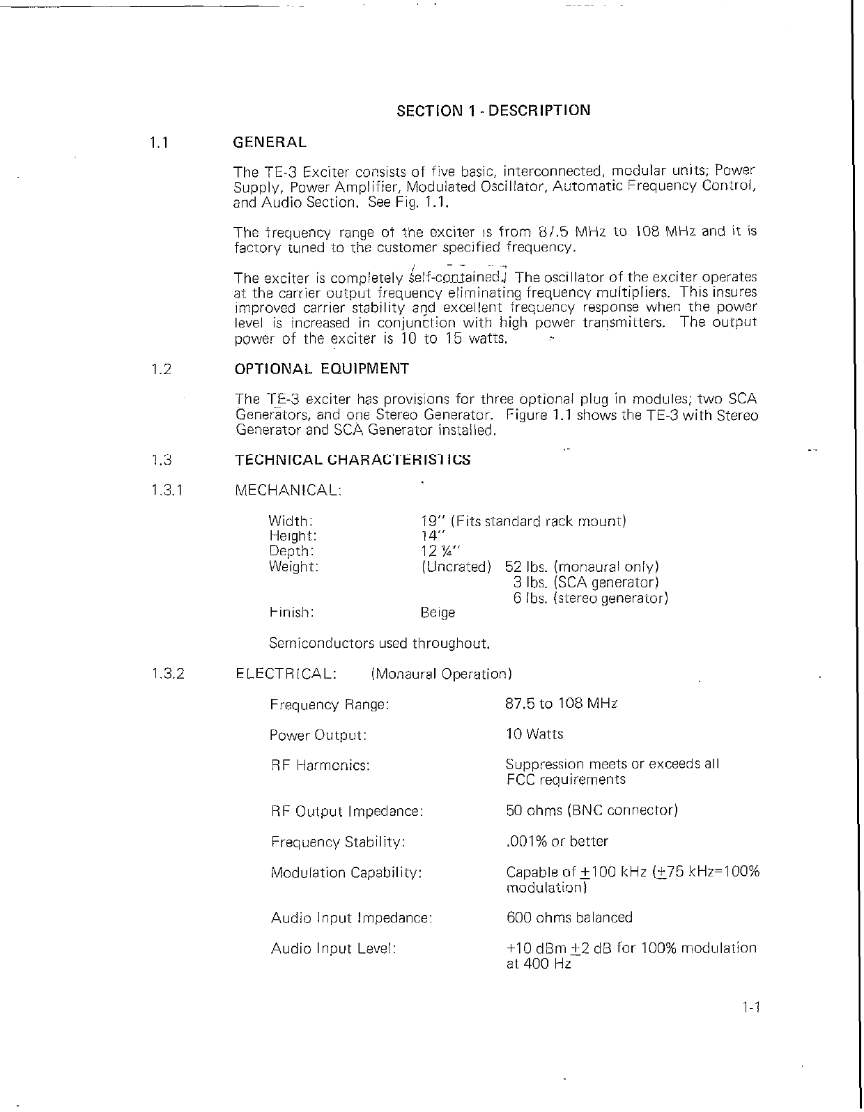
1.1 GENERAL
The TE-3 Exciter consists of five basic, interconnected, modular units; Power
Supply, Power Amplifier, Modulated Oscillator, Automatic Frequency Control,
and Audio Section, See Fig. 1.I.
1.2
1.3
1.3.1
The frequency range of the exciter is from 87.5 MHz to 108 MHz and it is
factory tuned to the customer speci.fied frequency.
The exciter is completely &If-contained.) The oscillator of the exciter operates
at the carrier output frequency eliminating frequency multipliers. This insures
improved carrier stability and excellent frequency response when the power
level is increased in conjunction with high power transmitters. The output
power of the exciter is 10 to 15 watts. :
OPTIONAL EQUIPMENT
The 15-3 exciter has provisions for three optional plug in modules; two SCA
Generators, and one Stereo Generator. Figure 1.1 shows the TE-3 with Stereo
Generator and SCA Generator installed. .-
TECHNICAL CHARACTERISTICS
MECHANICAL:
Width:
Height: ;!?I:: (Fits standard rack mount)
Depth: 12 ‘Yl”
Weight: (Uncrated) 52 Ibs. (monaural only)
3 Ibs. (SCA generator)
6 Ibs. (stereo generator)
Finish: Beige
Semiconductors used ,throughout,
1.3.2 ELECTRICAL: (Monaural Operation)
Frequency Range: 87.5 to 108 MHz
Power
Output:
10 Watts
RF Harmonics: Suppression meets or exceeds all
FCC requirements
RF Output Impedance: 50 ohms (BNC connector)
Frequency Stability: .OOl% or better
Modulation Capability: Capable of+100 kHz Ii75 kHz=lOO%
modulation)
Audio Input Impedance: 600 ohms balanced
Audio Input Level: +I0 dBm+2 dB for 100% modulation
at 400 Hz
l-l

Audio Frequency Response:
Distortion:
FM Noise:
AM Noise:
Standard 75 microsecond FCC pre-
emphasis curve, +I di3. 30-15.000 Hz
.5%, 30 to 15,000 Hz
65 dB below 100% modulation
(ref. 400 Hz.1
70 dB below reference carrier AM
modulated 100%
1.3.3
Temperature: -200 to +5oo c
Altitude: 7,500 feet
Power Requirements: 117 V AC, single phase, 60 Hz, 85 watts
ELECTRICAL: (Stereophonic Operation)
Pilot Oscillator:
Pilot Stability:
Audio input Impedance
(Left and Right):
Audio Input Level:
(Left and Right):
Audio Frequency Response
(Left and Right):
Distortion (Left and Right):
FM Noise (Left and Right):
Stereo Separation (Left to Right
or Right to Left Channel):
Sub-Carrier Suppression
(With or without
modulation present):
* Crosstalk (Main channel to
sub-channel or sub-channel
to main channel):
Sub-Carrier 2nd Harmonic
Suppression (76 kHz):
NOTE: Stereophonic mea.w&ent~ to be made with an FCC
approved monitor. ... , ,._
l-2
* Measurement to be made using an L=R signal for sub-channel crosstalk and an
L=-R signal for main channel crosstalk.
Crystal controlled
19 kHz +I Hz, 0’ to 50’ C
600 ohms balanced
+lO dBm+l dB for 100% modulation
at 400 Hz
Standard 75 microsecond, FCC pre-
emphasis curve, +I dB, 50-l 5,000 Hz
1% or less, 50-I 5,000 Hz
60 dB (minimum) below 100%
modulation (ref. 400 Hz)
._ -.--
35 dB (minimum) 50 to 15,000 Hz
42 dB (minimum) below 90% modulation
42 dB (minimum) below 90% modulaton,
50-I 5,000 Hz
60 dB or better below 100% modulation
_._.., -.

1.3.4 ELECTRICAL: (SCA Operation)
Frequency:
Frequency Stability:
Oscillator Type:
Modulation: Direct FM
Modulation Capability: Capable of 27.5 kHz (25 kHz considered
100% modulation)
Audio Input Impedance?
Audio Input Level:
Audio Frequency Response:
Distortion:
FM Noise (Main channel
not modulated):
Crosstalk (Sub-channel
to main channel and
stereophonic sub-channel):
** Crosstalk (Main channel
to sub-channel):
Any SCA channel between 25 and 75 kHz
i500 Hz
Two Colpitts heterodyned to produce
desired output frequency
600 ohms balanced
+8 dBm,+3 dB for 100% modulation
at 400 Hz
41 kHz and 67 kHz, 50 microsecond,
modified pre-emphasis
67 kHz response modified for proper
operation when used with stereo to
conform to FCC specs
1.5% (or better) 30.7,000 Hz
55 dB minimum (ref. 100% modulation
400 Hz)
-60 dB or better
50 dB below 100% modulation (ref. 400 Hz)
with main channel modulated 70% by
frequencies 30-I 5,000 Hz
** Crosstalk measurements to be made from an FCC approved monitor using
75 microsecond de-emphasis,
Automatic Mute Level: Variable from 0 to 40 dB below 100%
modulation
Remote Control: Exciter is internally equipped to be
locally or remotely switched from
monaural to stereo operation. On
monaural operation, normal right audio
input connections are switched to the
41 kHz SCA position, if used. Remote
functions are accomplished by a single
set of external relay contacts, (closure
required for stereo operation). An ex-
ternal relay must provide a holding
function.
I-3

LYE0
.ATOR
SCA GENERATOR
IOPTIONAL)
FRONT
VIEW
FIG. 1.1

FRONT
VIEW
FIG. 1.2

MUTE
LEVEL J
ADJUST TJ2
GROUNDI I \
TJI
TJ3 OUTPUT
\ FREOUENCY
ADJUST
PILOT
METER FUNCTION
SELECTOR SWITCH
FRONT
VIEW
FIG. 1.3
l-6
.
l/MONO/
IOTE
TCH

SECTION 2 - INSTALLATION
2.1 DAMAGE CLAIM INFORMATION
In case of damage, notify the delivering carrier at once. After he has approved
the damage report order new part(s) from Gates Radio Company, using the
parts list for description and individual identification.
2.2 UNPACKING AND INSPECTION
The container and packing should be removed only after a careful examination
of the outside of the carton for indications of possible mishandling.
Retain packing material untv installation is complete and the TE-3 is placed in
operation.
2.3 UNPACKING CHECK LIST
When the TE-3 is shipped as a separate unit, the following items are furnished
and packed separately:
EQUIPMENT
Basic
TE-3 Cabinet
Power Supply
Modulated Oscillator (Module)
Audio Unit (Module)
AFC Control (Module)
Power Amplifier (Module)
Technical Manual
992 1726 OC2
992 2696 001
992 1830 001
992 2697 001
992 1715001
8881042001
Optional
SCA Generator 1 or 2 Modules(s) 9946507001
Stereo Generator (Module) 9946533001
2.4 MECHANICAL DETAILS
GATES PART NO.
992 273.5 001
The modular design assures easy access to all parts during inspection, routine
maintenance and repair. Each module may be released from the chassis by
means of thumb screws, and operated external to the chassis.
The exciter output may be connected into a dummy load, antenna, or a follow-
ing amplifier stage,
2.5 POWER REQUIREMENTS&CONNECTION
A 117 V AC, 60 Hz, single phase, 85 watt, fuse or circuit breaker protected,
power source is required. No additional equipment is necessary for operation.
Connect the input power to terminals & 8 of TBl. See Fig. 2.1
When the AC input is 117 VAC, the black and green/black primary leads of the
transformer Tl should be used. If the AC input voltage is less than 105 VAC,
the black and white/black primary leads should be used, If the AC input volt-
age is greater than 125 VAC, the black and white primary leads should be used.
Rev. 12/74 2-1

2.6
2.7
R.F. OUTPUT CONNECTION
The R.F. connection to the exciter is a BNC connector (Jl) on the rear of the
unit. See Fig. 2.1. Use coaxial cable type RG58A/U.
ADDITIONAL CONNECTIONS - See Fig. 2.1
Additonal connections are located on the terminal board TBI on the rear of
the exciter. They are as follows:
1-2-3: Left Audio Input (2 is shield)
4-5-6: Right Audio Input (5 is shield)
,, or SCA
’ J-8:
AC Input
9-10: AFC Alarm (N.C.)
1l-12-13: SCA Audio (12 is shield)
14-15: Stereo-Mono Switch
16-17-18-19-20:
Spare
2-2

RIGHT
AUDICI
INPUT
AC
POWER
AFC
ALARM
STEREO
SWlTCH
REAR
VIEW
FIG. 2.1
2-3

SECTION 3. OPERATION &ADJUSTMENT
3.1 FRONT PANEL CONTROLS
The following table gives the identification and function of the front panel con-
trols, (See Fig. 1.1 for basic modules).
TABLE 3.1
FUSES&TEST POINTS
LOCATION AND IDENTIFICATION
IDENTIFICATION TYPE FUNCTION
Power Supply
FZ
Sl
Al
Power Amplifier
RI1
Modulated Oscillator
R29
Audio Unit
AFC Unit
Stereo Generator
::I
TJ2
R68
R53
R27
R24
SCA Generator
TJI Jack (Test)
TJ2 Jack (Test)
R30 Potentiometer
Sl 4 position knob
Fi32 Potentiometer
3 Amp Fuse
2 Amp Fuse
Toggle Switch
Green Light
Potentiometer
Knob controlled Pot,
Toggle Switch
Toggle Switch
Potentiometer
DC Microammeter
5 position knob
controlled switch
Toggle Switch
Jack (Test)
Jack (Test)
Potentiometer
Potentiometer
Potentiometer
Potentiometer
Protect +24 Volt circuits
Protect 115 V AC circuits
Energize/De-energize unit
Indicates unit energized
DRIVE Adjust
AFC Adjust
STEREO/MONO/REMOTE
SELECT
AFC ON/OFF
FREQ. ADJUST
Indicates indexed function
Indicates meter function
COMPOSITE/PILOT OFF
COMPOSITE OUTPUT
GROUND
L + R GAIN Adjust
OUTPUT LEVEL Adjust
PI LOT GAIN Adjust
PI LOT PHASE Adjust
OUTPUT
GROUND
OUTPUT LEVEL Adjust
MUTE DELAY Select
MUTE LEVEL Adjust
3-1
This manual suits for next models
1
Table of contents
Other Harris Industrial Equipment manuals


Popular Industrial Equipment manuals by other brands

Lochinvar
Lochinvar LOKE8-50 Installation, Commissioning, Maintenance and User instructions

FALK
FALK Steelflex T10 Installation and Maintenance

Conquip
Conquip COSHH Store user guide

BLAUBERG Ventilatoren
BLAUBERG Ventilatoren HW installation instructions

morse
morse 185M Series Operator's manual

Pfeifer
Pfeifer HIT Translation of the original manual


