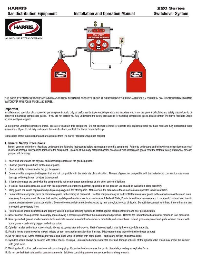
Harris DataSmart 763 User manual

Model 763 DataSmart
Programmable Fully Automatic Manifold w/Telemetry
Installation & Operation manual

pg. 2
CONTENTS
Safety Guidelines……………………………………………………………………………….3
User Responsibility…………………………………………………………………………….4
Introduction To The Model 763 DataSmart Gas Distrubution System………………..5
Features…………………………………………………………….…………………….5
Check Back Feature…………………………………………………………………… 6
Economizer Function ………………………………………………….……………… 6
Installation Instructions…………………………………………………………….………….6
Reference Material………………………………………………………………………..7
Preparing For DataSmart……………………………………………………….………..7
General Installation Guidelines………………………………………………….……...8
Mounting Instructions……………………………………………………………………8
Attaching Cylinders…………………………………………………………………………….9
For A Two Cylinder Manifold……………………………………………………………9
Manifold For More Than Two Cylinders………………………………………..………11
Pressurizing The DataSmart Manifold System……………………………………………12
DataSmart Operation Instructions…………………………………………………………..12
Connecting To Power……………………………………………………………………12
DataSmart Initial Setup (Username/Password, Machine Name, Configure
Wifi, Registration Code, Telemetry Configuration, User Selectable
Features, System Parameters, User Selectable Features...........................13-17
DataSmart Production Analytics……………………………………………………………17
Appendix A –Cloud-Based Architectur/Security and Data Storage………………….18
Appendix B –DataSmart Wiring Diagram…………………………………………………19
Appendix C –Troubleshooting Guide………………………………………………………20
Appendix D –Piping and Instrumentation (P&ID) Diagram…………………………….21
Appendix E –DataSmart Model 763 GUI Instructions…………………………………...22

pg. 3
SAFETY GUIDELINES
Basic safety precautions must be followed to reduce the risk of fire, electrical shock or injury.
• Connect the DataSmart to the correct line voltage. A label on the product identifies what voltage it is wired
for. CONNECTION TO AN INCORRECT VOLTAGE CAN CAUSE SERIOUS DAMAGE TO THE PRODUCT
AND WILL VOID ANY WARRANTY.
• Install the DataSmart where the ambient temperature range is between - 0° F and +120° F.
•DataSmart NEMA enclosures and controls are intrinsically safe and can be used to control and regulate
certain flammable gases such as hydrogen, ethylene, methane and propane (LP Gases). In addition,
DataSmart can be used in Class 1, Division 2, Groups B and D environments where ambient explosive gases
or mixtures are not expected to be present in normal operation.
• DataSmart cannot be used for acetylene gas service. Do not install this product in a Class 1, Division 1,
(Group A, B, C or D) environment where ambient explosive gases or mixtures are expected to be present in
normal operation.
• If product appears damaged in any way, do not use and contact Harris Products Group Technical Service.
• Consult the cylinder distributor for the proper use of cylinders and for any restrictions on their use (such as
flow rate and temperature requirements).
• Store cylinders with valve caps screwed on, and chain cylinders to a supporting wall or column. • Handle
cylinders carefully and only with valve caps screwed on. The cap will reduce the chance that the cylinder valve
will break off if the cylinder is accidentally dropped or falls over. The cap also protects the cylinder valve from
damage to screw threads, which could cause leaky connections.
• No smoking should be permitted near oxygen, nitrous oxide, any other oxidizer, flammable gases, or
flammable mixtures, or in areas where cylinders are stored.
• Where an oxidizer (such as nitrous oxide or oxygen) is used, the manifold and cylinders must be kept clean.
No oil, grease, or combustible substances should come in contact with oxygen or nitrous oxide storage or
handling equipment. Such materials in contact with oxygen or nitrous oxide are readily ignitable and, when
ignited, will burn intensely.
• Never lift gas cylinders with a magnetic lifting device.
• Never use an open flame when leak testing.
• Always open valves slowly when high-pressure gases are being used.
• Always be sure that a cylinder contains the correct gas before connecting it to any manifold.
• Always leak-test any manifold or distribution pipeline before using.
• Always be sure that the gas in a pipeline is the correct gas for the intended use.
• Always close all cylinder valves before disconnecting cylinders from a manifold.
• Always remove all empty cylinders from a manifold before connecting full cylinders.

pg. 4
• Always test cylinders to be sure the cylinders are full before connecting to a manifold. All gas distribution
piping systems must meet the appropriate industrial standards for the intended service and must be thoroughly
cleaned before using. For the United States, some applicable safety rules and precautions are listed below:
1. American National Standards Institute standard Z49.1, Safety in Welding and Cutting, American
Welding Society, 2501 NW Seventh Street, Miami, Florida 33125
2. N.F.P.A. Standard 51, Oxygen-Fuel Gas systems for Welding and Cutting, N.F.P.A., 470 Atlantic
Avenue, Boston, Massachusetts 02210
3. N.F.P.A. Standard 51B, Cutting and Welding Processes (same address as #2).
4. Local Ordinances
5. O.S.H.A. Standard 29 CFR
6. C.G.A. Pamphlet C-4, American National Standard Method of Marking Portable Compressed Gas
Containers to Identify the Material Contained.
7. C.G.A. Pamphlet G-4, Oxygen –Information on the properties, manufacture, transportation, storage,
handling, and use of oxygen.
8. C.G.A. Pamphlet G-4.1, Equipment Cleaned for oxygen service.
9. C.G.A. Pamphlet G-4.4, Industrial Practices for Gaseous Oxygen Transmission and Distribution
Piping Systems. 10. C.G.A. Pamphlet G-5, Hydrogen –Information on the properties, manufacture,
transportation, storage, handling, and use of hydrogen.
11. C.G.A. Pamphlet G-6, Carbon Dioxide –Information on the properties, manufacture, transportation,
storage, handling, and use of carbon dioxide.
12. C.G.A. Pamphlet G-6.1, Standard for Low Pressure Carbon Dioxide Systems at Consumer Sites.
13. C.G.A. Pamphlet P-1, Safe Handling of Compressed Gases in Containers. 15. C.G.A. Safety
Bulletin SB-2, Oxygen Deficient Atmospheres. C.G.A. Pamphlets can be obtained from the
Compressed Gas Association, 3
USER RESPONSIBILITY
Service to this product should only be performed by HARRIS PRODUCTS GROUP.. Requests for service may
be made through HARRIS CUSTOMER SERVICE. HARRIS accepts no responsibility for damage or injury if
this product is modified in any way. HARRIS assumes/accepts no liability or responsibility for damage to
individuals or equipment that may occur when using this product.

pg. 5
INTRODUCTION TO THE MODEL 763 DATASMART GAS DISTRIBUTION SYSTEM
The Model 763 DataSmart manifold is a gas distribution system used to monitor, control and switch the flow of
gas from
bulk, cryogenic or high pressure cylinders while maintaining a settable, constant delivery pressure to the facility
or process. It consists of an electronically controlled switchover valve that can be programmed to switch over
at two independent pressures depending on the input source. The manifold offers two stage pressure control
to the downstream pipeline assuring precise delivery pressure control.
Input pressures are monitored on both the right and left side by a local LCD touchscreen display. The display
also indicates the gas source as either a high pressure cylinder, a liquid dewar or a bulk gas source (bulk tank
or cylinder packs). The outlet pressure of the system is also monitored and displayed on the LCD screen.
Outlet pressure adjustment is available using an adjusting screw on the delivery regulator from an access port
on the outside of the Mechanical Enclosure.
A series of indicator lights and messages on the LCD screen show the status of the system at any given time.
System status can also be monitored remotely via a built-in, wifi based telemetry system that sends and
retrieves data from a remote server to the user’s computer or mobile device. This integrated telemetry system
also has the capability to send messages and alerts via email or SMS. Remote monitoring is a subscription
based service that is available from The Harris Products Group.
FEATURES
•Designed to connect to multiple gas sources: High pressure cylinders, liquid dewars, cylinder packs or
bulk gas systems
•Capable of operating with inlet pressure provided by 230, 350, and 500 PSI liquid cylinders, 3,000 PSI
high pressure cylinders, or any combination.
•Check Back Feature for liquid dewars
•Economizer for reserve side liquid dewars
•Programmable switchover pressure for both right and left side from 70 to 2000 psig
•LCD Touchscreen control
•Secure login to protect settings
•Built-in, Wifi-based telemetry system and data acquisition via a remote server (connection to a Wifi
network required)
•Customized alerts and notifications via email and SMS
•Optional mass flow meter to measure current gas usage or usage over time
•Class 1, Division 2 NEMA Enclosures
•Optional Remote A/V Alarm
•Modular, expandable header system for multiple cylinders
•Output pressures up to 450 psi available
•Integral 500 scfh heaters for CO2, N2O or mixtures
•Configurable flex hoses up to 120” available
•Designed for high purity or industrial grade gases
•Brass models designed for high flows up to 3000 scfh
•Brass and SS models available

pg. 6
CHECK BACK FEATURE
When using liquid cylinders, it is not uncommon for the primary side pressure to drop below the switchover
point even if there is still a significant amount of gas left in the cylinder. This could be caused by an increase in
downstream demand during peak gas usage, or, when the liquid volume in the cylinder becomes low.
As a result, manifold systems without a Check Back feature may do one of two things –
1. Switch to the reserve side until the pressure builds back up and then switch back to the former primary
side. This will happen repeatedly resulting in both sides of the manifold being depleted at the same time,
or,
2. Switch to the reserve side permanently resulting in a significant amount of gas left in the cylinder
unused.
To avoid either of these situations, the Model 763 DataSmart manifold has an electronically controlled Check
Back feature that performs as follows:
a) If the primary side pressure goes down below the switchover point, the system temporarily switches
over to the reserve side. The system does not go into alarm mode at this point and the system
status does not change.
b) The LCD screen indicates “Check Back” mode.
c) After 30 minutes, the system checks back to see if reserve side pressure has recovered to 15% or
more above the switchover point
d) If so, the system switches back and uses gas until the switchover pressure is reached
e) If not, the system goes into alarm mode and shows empty
f) The DataSmart system will perform steps a, b and c three times. After that, the system goes into
alarm mode and switches over to the reserve side. System status lights will change at this time.
g) After the system goes into alarm mode, any increase in pressure 15% above the switchover point
on the empty side resets the check back feature and assumes the empty cylinder has been
replaced.
ECONOMIZER FUNCTION
Liquid cylinders that are in reserve with no gas being used will continue to build head pressure until the relief
valve opens venting gas to the atmosphere where it is lost and cannot be used. The Model 763 DataSmart is
constantly sensing pressure being built up on the reserve side. If the reserve side pressure builds up to within
85% of the relief valve setting, the system will switch over to the reserve side for 5 minutes to use gas and
lower the building head pressure before the relief valve activates. The DataSmart system will continue to
sense increasing pressure on the reserve side and activate in 5 minute intervals so long as a liquid dewar is
installed on the reserve side. This is also indicated on the LCD screen as a function of the “Check Back”
feature.

pg. 7
INSTALLATION INSTRUCTIONS
REFERENCE MATERIAL
The following safety bulletins/standards are available on the Compressed Gas Association’s website
(www.cganet.com) or at (703) 412-0900:
•SB-2 Oxygen Deficient Atmospheres
•SB-10 Correct Labeling & Proper Fittings On Cylinders/Containers
•SB-15 Avoiding Hazards In Confined Work Spaces During Maintenance, Construction And Similar Activities
•SB-19 Potential Valve Thread & Cylinder Thread Mismatch
•E-11 Compressed Gas Association Standard for Cylinder Discharging Manifolds for Pressures Up To 3000
PSI
Figure 1 –Mounting Dimensions
The above Figure 1 shows a typical installation with critical mounting dimensions. The Touchscreen
Control Box can be mounted in close proximity to the Mechanical Enclosure. The Remote A/V Alarm
Box can be mounted up to 200 feet away with the proper cable. Contact Harris Technical Service for
more information.
WARNING
It is important that when installing this manifold system that no oil or contaminants come in contact with any manifold parts. If parts
have been contaminated during shipment, do not use and contact Harris Technical Service (800-241-0804, Option 2) for
assistance.
Caution
Read and understand installation instructions thoroughly prior to using this system. If you have any questions about the
installation, contact Harris Technical Service (800-241-0804, Option 2) for assistance.

pg. 8
Preparing for DataSmart
To use DataSmart, basic requirements must be met. You need an internet connection to transmit data
frames to the DataSmart server. To provide access to the Internet, you must connect to a wireless
access point with Internet access. DataSmart analysis and subscription services require access to the
internet to transmit data to the DataSmart data server in the cloud. The DataSmart data server
https://ams.harrisproductsgroup.com is located at IP address 207.89.49.159. Opening port 443 outbound
only in your network firewall allows each DataSmart to send data via HTTPS. Contact your local IT
department for assistance in connecting DataSmart machines to the internet and firewall configuration.
GENERAL INSTALLATION GUIDELINES
1. Installation should be performed by personnel knowledgeable in the handling of compressed gases
and familiar with compressed gas equipment.
2. Choose a location well ventilated for installation.
3. Use proper precautions when dealing with any compressed gas.
4. The user should be familiar with the chemical and reactive properties of the gas being used (Read
the MSDS of the gas being used).
5. The DataSmart gas distribution system requires connection to the internet via a Wifi network in
order to logon, register and set up the system. If connection to a Wifi network is not possible, the
use of a Mifi or Personal Hotspot may be necessary to complete installation of this system.
6. Install the DataSmart where the ambient temperature range is between 0° F and +120° F.
7. Do not install this product in a hazardous environment. The DataSmart Mechanical Enclosure and
Touchscreen Control Box are designed with a Class 1, Division 2 NEMA enclosure and can be used
for certain flammable gases. However, the system must be installed in a well ventilated location.
8. If product appears damaged in any way, do not use and contact The Harris Products Group
Technical Service.
MOUNTING INSTRUCTIONS
1. The Mechanical Enclosure should be mounted to a rigid structure capable of supporting 100+ lbs. Do
not attempt to mount to a sheet rock wall or similar surface without the use of properly installed
mounting channel or railing.
2. Mount the Mechanical Enclosure at a height that is easily accessible to the user so that the outlet
regulator can be adjusted as necessary and the access door can be opened, if required.
3. Locate the mounting tabs on the Mechanical Enclosure and the mounting dimensions from Figure
1.
4. Secure the Mechanical Enclosure using the mounting brackets at the top and bottom of the
enclosure. Mounting hardware is not included.
5. Once the Mechanical Enclosure is secured, mount the Touchscreen Control Box in a similar manner
at a height no more than eye level so that screen information can easily be seen and modifications to
the set up can be made. The Touchscreen Control Box should be mounted in close proximity to the
Mechanical Enclosure (the standard connection cable is 10 ft.), or, with a longer cable, this box can be
mounted up to 100 ft away.
6. Mount the A/V Remote Alarm Box (if supplied), in a similar manner to the Touchscreen Control
Box. Mount at a height accessible so that the alarm shut-off can be activated. The A/V
Remote Alarm box can be mounted up to 200 ft. away with proper cable. The standard cable

pg. 9
supplied is 10 ft.
ATTACHING CYLINDERS
The below safety guidelines should always be followed when handling compressed gas cylinders.
1. Handle cylinders carefully and only with valve caps screwed on. The cap will reduce the chance that the
cylinder valve will break off if the cylinder is accidentally dropped or falls over. The cap also protects the
cylinder valve from damage, which could cause leaky connections.
2. No smoking should be permitted near oxygen, nitrous oxide, any other oxidizer, flammable gases, or
flammable mixtures, or in areas where cylinders are stored.
3. Where an oxidizer (such as nitrous oxide or oxygen) is used, the manifold and cylinders must be kept
clean. No oil, grease, or combustible substances should come in contact with oxygen or nitrous oxide
storage or handling equipment. Such materials in contact with oxygen or nitrous oxide are readily
ignitable and, when ignited, will burn intensely.
4. Never lift gas cylinders with a magnetic lifting device.
5. Never use an open flame when leak testing.
6. Always open valves S-L-O-W-L-Y when high-pressure gases are being used.
7. Always be sure that a cylinder contains the correct gas before connecting it to any manifold.
8. Always leak-test any manifold or distribution pipeline before using.
9. Always be sure that the gas in a pipeline is the correct gas for the intended use.
10. Always close all cylinder valves before disconnecting cylinders from a manifold.
11. Always remove all empty cylinders from a manifold before connecting full cylinders.
12. Always test cylinders to be sure the cylinders are full before connecting to a manifold.
For a two cylinder manifold –
1. Attach the flexible hoses (pigtails) to the right and left side inlet connections on the Mechanical
Enclosure as shown in Figure 2. The manifold inlets are located at the bottom of the
Mechanical Enclosure.
2. One end of the flex hose (pigtail) will connect directly to the Mechanical Enclosure and should
be wrench tight using Teflon tape as a thread sealant. The other end will have a CGA
connection with a check valve specific for the gas being used which will attach directly to the
cylinder. This is a metal-to-metal seal and no Teflon tape or other thread sealant should be
used.

pg. 10
Figure 2 –Two Cylinder Setup
Manifold for more than two (2) cylinders
Harris uses a modular header system for attaching multiple cylinders to the DataSmart manifolds
(Ref. Figure 4). See Figure 3 for proper installation. The modular design allows greater flexibility
for expansion and/or re-configuration of your multi-cylinder gas manifold. Below are detailed
instructions on how to install the modular headers.
Figure 3 –Modular Manifold Installation
Table 1 –Component Part Legend for Modular Headers

pg. 11
The header manifold is to be attached to a wall or other secure structure. Each valve will have
a typical distance of either 5”or 10”from center to center depending on length of tube being
used. The header assembly does not come with mounting hardware as the customer should
choose fasteners appropriate for the mounting surface.
1. The start valve (1) has two openings, one end connecting to the manifold hub and the other
end to the header tube. NOTE: Brass models will have a ½” NPT opening and Stainless Steel
models will have a ¼” NPT opening.
2. The start valve (1) opening will be used to connect to the inlet of the manifold hub. On the
opposite end, a 1.045-14 NGO opening will be used to attach the header tube.
3. To connect the start valve to header tube, a 1- ⅝” wrench and 1-⅛” wrench will be required.
Use the 1-⅝”wrench to hold the valve body and the 1-⅛” wrench to tighten the header tube.
Torque each header tube (2) connection to 40 ft-lbs.
4. Connect mid valve (3) to the unattached end of the header tube. Ensure valve bodies are
parallel to one another. Use the 1-⅝” wrench to hold the valve body and the 1-⅛” wrench to
tighten the header tube. Torque to 40 ft- lbs.
5. Following steps 2 and 3, attach additional header tubes and mid valves as required by
application.
6. On the final mid valve (3) of the assembly, connect header plug (4) to the rear opening. Use
the 1-⅝” wrench to hold the valve body and the 1-⅛” wrench to tighten the plug. Torque to 40
ft-lbs.
7. Attach a valve bracket (6) to every valve in the assembly using the screws (8) provided.
8. Match header assembly dimensions to the mounting surface. Properly align and fasten wall
bracket to the mounting surface.
9. Mount the header assembly by connecting the valve bracket (6) and wall bracket (7) using
the provided screws and nuts. The wall bracket assembly allows for distance adjustments from
mounting surface to the header assembly.
10. Attaching the hoses: Remove either bottom or top plug (5) on the valve. Assemble pigtail to
valve block using teflon tape to seal the threads. Wrench tighten from 18 ft-lbs up to 25 ft-lbs of
torque.

pg. 12
Figure 4 –Multi-Cylinder Setup
PRESSURIZING THE DATASMART MANIFOLD SYSTEM
1. The DataSmart manifold should be fully assembled with cylinders, headers and all
flexible hoses attached and torqued to the proper specs.
2. The outlet port on the Mechanical Enclosure should be plugged, or, if utilizing an outlet
isolation valve, make sure it is in a closed position. If this is not possible, turn the
adjusting screw on the outlet regulator counter-clockwise until it turns freely. This will
insure that there is no outlet pressure when initially pressurizing the system. The outlet
regulator adjusting screw can be accessed from outside the Mechanical Enclosure by
removing the plug from the right side top.
3. Once this is complete, S-L-O-W-L-Y pressurize the system by turning on cylinder
valves and/or header valves for both the right and left sides. Check each joint for
leaks with an approved leak detection solution or warm soapy water. Increase torque
slightly, at each joint, if needed, to eliminate leaks.
4. Do not torque any connection to greater than 60 ft-lbs. If leaks cannot be eliminated,
contact your distributor or Harris Products Group Technical Service.
DATASMART OPERATION INSTRUCTIONS
1. Connecting to Power
a. Connect cable from Mechanical Enclosure to the Touchscreen Control Box
b. If included, connect the A/V Remote Alarm Box to the Touchscreen Control Box
c. Connect the Touchscreen Control Box to a 120VAC 50/60Hz power source.
CAUTION: Connection to an incorrect voltage can cause serious damage to the product and will
void the warranty.

pg. 13
2. DataSmart Initial Setup
a. Follow the steps below to configure the DataSmart for first-time use. Initial configuration values
may be changed at any time. When the system starts up for the first time it will present a list of
steps that must be taken before it will be fully functional. Press the button to the right of each
step to set the corresponding values.As each step is completed, the button will show a green
check mark to indicate success. Notification icons in the lower left corner of the screen indicate
functionality, mode and wi-fi connection status.
1. Once connected to power, the DataSmart will boot up and default to the login screen (See
Figure 5). Log in to the system. The factory default Username and Password are as
follows. These can be changed at any time by accessing Machine Username Password
Update from the System Configuration screen.
Username: HPG_AMS
Password: HPG@123
Figure 5
2. Create Machine Name: Machine Name is a way to easily identify a unit in the analytics
dashboard. If there are multiple DataSmart systems tied to a specific contract, each system
must be uniquely named. Enter a name for the unit and press OK to save. NOTE: Machine
name should not contain any special characters such as #, @ etc. The Machine Serial
Number will be assigned prior to purchase and will be visible upon first start-up.

pg. 14
Figure 6 –Machine Name Screen
3. Configure Wi-Fi: Select the appropriate SSID (Wi-Fi Network Name) to allow connectivity to
the DataSmart server.Enter the password and press OK to save. An activeWi-Fi connection
is required to complete this step and to initialize the unit. If the DataSmart machine is unable
to connect to a Wi-Fi network, it is recommended to turn the power off, then re-start the
machine and return to the Configure Wi-Fi step. If no password is required for the WiFi
network, then press ENTER at the password screen to bypass this requirement. The unit
cannot access a WiFi network that requires a terms of use acknowledgement, even if no
password is required. Adding the MAC Address to the WiFi network can help facilitate
connection.
Figure 7 –WiFi Setup
4. Registration Code: Enter the registration code that was provided as part of the DataSmart
agreement. Press OK to save. The unit will contact the DataSmart server to validate the
code. Depending on your internet connection speed, it may take several minutes to
complete this step.

pg. 15
Figure 8 –Registration Code
5. Telemetry Configuration: Select the appropriate configuration for your setup:
a. AMS is the integrated telemetry system (recommended)
b. Standalone telemetry with integrated sensor (user will connect using DataSmart
sensors)
c. Standalone telemetry with end-user sensors (user will connect their sensors)
6. User Selectable Features: Configure the settings for operation:
a. Unit of Measurement –select Imperial or Metric
b. System Priority –select the side of the distribution system that DataSmart should
prioritize for gas delivery: Left Bank; Right Bank; First In, First Out (FIFO).
NOTE: Liquid cylinders or bulk systems should always be the priority bank, i,e., a liquid
dewar that is on the left side should be set up as Left Bank Priority. If there are liquid
dewars on both sides, then priority should be set as FIFO.
c. Bank Configuration –DataSmart will enter bank configuration based upon System
Priority selection. Select Gas Source and Gas Type for each bank based upon your
setup. The available Gas Types are determined by the Gas Source selection. Note:
Bulk System or Liquid Dewar should always be set as the Gas Source on the
PRIMARY bank.

pg. 16
Figure 9 –Units and System Priority
d. The following parameters must be selected and programmed on initial setup:
1. Choose Pressure Cylinder, Liquid Dewar, Cylinder Bank or Bulk system from the
drop-down menu for both right and left sides.
Figure 10 –Bank Configuration
2. Select cylinder relief valve pressure for each liquid dewar
3. Program desired switchover pressure for each side. Switchover pressure can be
adjusted up or down in 12 psig increments.

pg. 17
Figure 11 –Bank Configuration
4. Select Container Size if using a bulk system
5. Daily Decay Venting Allowance % (Bulk system only)
6. Adjust outlet regulator to desired pressure (access port from outside the
Mechanical Enclosure)
Once the two banks are configured, the system is ready to begin gas flow. Press
CONFIRM to verify that the Delivery Pressure is correct. Press DONE to complete the
setup process.
DATASMART PRODUCTION ANALYTICS
Once the machine is installed and connected to the internet via a WiFi network, the
production analytics can be created which will give important data regarding your gas
usage. From your computer or mobile device, go to
https://DataSmart.harrisproductsgroup.com/login to access and set up the analytics.
You will have to contact Harris Products Group Customer Service at 800-241-0804
Option 2 to set up your account and register. Once your subscription service has been
activated, follow the directions on the web application to set up messages and alerts
based on your desired conditions at the gas manifold.
The web application can also generate reports on gas usage, switchover times and
historical data to help better manage your gas system.

pg. 18
APPENDIX A
Cloud-Based Architecture
DataSmart is a cloud-based system. This means that there is no dedicated computer required in your company
to collect and store the data. Each machine requires a wireless internet connection in order to report
production data. DataSmart initiates the transfer of information through a firewall to the data center. Data is
transferred directly from DataSmart. Production data is accessible using a web browser and a secure login.
Security and Data Storage
Each DataSmart customer’s data is stored in a state-of-the art data center. When viewing the DataSmart
application, high-security, industry-standard encryption is used. The hosting center is a SSAE 16 SOC 2 Type
II compliant facility. SSAE 16, also called Statement on Standards for Attestation Engagements 16, is a
regulation created by the Auditing Standards Board (ASB) of the American Institute of Certified Public
Accountants (AICPA) for redefining and updating how service companies report on compliance controls.
It is an acceptable method to obtain assurance of a service organization’s internal controls without conducting
separate assessments. Successful completion of the SSAE 16 SOC 2 Type II examination indicates that the
processes, procedures, and controls have been formally evaluated and tested by an independent auditing firm.
A service auditor’s examination performed in accordance with SSAE 16 SOC 2 Type II (Trust Principles) is
widely recognized. It represents that a service organization has been through an in-depth audit of their control
objectives and control activities, which often include controls over information technology and related
processes. A Type II report not only includes the service organization’s description of controls but also includes
detailed testing of the design and operating effectiveness.
The hosting center environment is built with state-of-the-art equipment, technology investments, and
operational expertise. There is an established disaster recovery program with redundancy and fail-over to
protect the information stored in the system.
Access Requirements
Each computer or mobile device must have access to the Internet to connect to DataSmart. All DataSmart
machines require access to the Internet to send data to the DataSmart data center. Every DataSmart machine
is identified by a unique device ID. This ID number is saved during registration and sent with each DataSmart
data packet to store the data. Refer to Chapter 2 Preparing for CheckPoint® for additional information.
Accessing Data
Access to company data is limited to DataSmart users assigned to a Company by that Company’s
Administrator. A user can be assigned to multiple Companies and will have access to each Company’s data
each time they log in. Depending on the User Role provided by the Administrator, the user may have access to
Equipment Configuration and User Management settings.
Network Capacity
Networks and Internet connections have limited bandwidth for sending data. Each DataSmart machine uses a
small amount of bandwidth. To estimate the bandwidth on your network, you can multiply the number of
DataSmart machines by the data quantity of data packets:
Every 5 minutes, each DataSmart machine sends a data frame to the DataSmart data center; the data
packet is about 68 Bytes in size.
The data frames use most of the available bandwidth. When estimating bandwidth, allow at least 10%
for additional occasional traffic and other network communications. If the network or Internet connection
is lost, the DataSmart machine continues to collect and buffer data until the network connection is re-
established. Once the Internet connection is reestablished, all the data is sent to DataSmart.

pg. 19
APPENDIX B
Wiring Diagram

20
APPENDIX C
Troubleshooting Guide
Problem Possible Cause Solution
No power Check to make sure control box is plugged up
Cables not connected properly
Check cable connectors to make sure they are engaged
Blown fuse
Check the fuse to see if it is blown/ replace if
LCD screen frozen; cannot edit Internal software error Reboot the system
Cannot connect to WiFi Internal firewall
Contact your IT department; see section "Preparing for
DataSmart" and Appendix A
Lost WiFi connection Poor signal strength Check signal strength and reconnect
Error message when programming
switchover pressures
Pressure differential between right side and
left side switchover is greater than 150psi
There cannot be more than 150 psi difference between
the right side and left side switchover pressures.
Readjust to parameters within this range.
Switchover pressures not programmed Program both right and left side switchover pressures
Switchover pressures set too low
Check switchover pressure settings and adjust to
Switchover pressures not set properly
Check to see that the switchover pressures are not set
too high. Contact Harris Technical Service for
guidelines on where switchover pressures should be
System not sized correctly for liquid dewars
More cylinders may need to be added; contact Harris
Technical Service for recommendations.
No subscription Contact Harris Customer Service to set up service.
No WiFi Connection Reconnect to WiFi
Not registered
Obtain registration number from machine and go to
https://datasmart.harrisproductsgroup.com/login
Flexible hose assembled incorrectly Check flow direction arrows on all flex hoses
Outlet regulator not set Adjust outlet regulator to desired outlet pressure
System does not boot up
System does not switch over
System switches back and forth
Cannot access DataSmart Web
Applications
No gas flow through manifold
Table of contents
Other Harris Industrial Equipment manuals
Popular Industrial Equipment manuals by other brands

Siemens
Siemens FLENDER H SH Series Assembly and operating instructions

SCHUNK
SCHUNK SVH Assembly and operating manual

Chamberlain
Chamberlain Commercial Protector System CPS-U installation instructions

BANDELIN
BANDELIN SONOREX TECHNIK RM 16.2 UH User instructions

Duro Dyne
Duro Dyne LS-5 owner's manual

Meler
Meler PS200 instruction manual

hager
hager UDKQ06 Series Mounting instructions

Zimmer
Zimmer GPP5000 Series Installation and operating instructions

ABB
ABB HT607956 Operation manual

Mathey Dearman
Mathey Dearman 8SA Parts and Operating Manual

KMC Controls
KMC Controls BAC-5051E Application guide

Branick
Branick 450 Installation, Operation & Repair Parts Information