ABB PowerCube PB/F Quick guide

—
DISTRIBUTION SOLUTIONS
PB/F - PB/FL type PowerCube
Installation and service instructions
Index
1. Packing and transport 3
2. Checking on receipt 4
3. Storage 5
4. Handling 6
5. Description 8
6. Instructions for operating the apparatus
and operation sequence of the units 24
7. Installation 28
8. Putting into service 27
9. Periodic checks 30
10. Maintenance operations 31
11. Accessories and spare parts 32
—
For your safety!
Make sure that the room is suitable for the
installation of electrical apparatus.
Make sure that all the installation, putting into
service and maintenance operations are carried
out by skilled personnel with in-depth knowledge
of the apparatus.
Make sure that all the installation, service and
maintenance operations comply with standard and
legal requirements for constructing the
installations in accordance with the regulations
for safety in the workplace.
Strictly follow this instruction manual.
Make sure that the ratings are not exceeded while
the apparatus is in service.
Responsible behaviour safeguards your own
and others’ safety!
For any requests, place contact the ABB
Assistance Service.
Pay the utmost attention to the notes shown in
the manual by the following symbol:
Make sure that the personnel working on the
apparatus have this manual to hand and all the
information required for correct intervention.

2PB/F - PB/FL type PowerCube - INSTALLATION AND SERVICE INSTRUCTIONS
—
Introduction
The instructions in this manual refer to standardised
PowerCube PB/F medium voltage fixed parts.
For correct use of the apparatus, please read the
manual carefully.
PowerCube PB/F fixed parts are designed for a large
number of installation configurations.
However, they do allow further technical and
constructional modifications to satisfy special
installation requirements.
Consequently, the information given below may
sometimes not contain instructions concerning
special configurations requested by the customer.
Apart from to the manual, it is therefore always
necessary to consult the latest technical
documentation (circuit and wiring diagrams,
foundation plans, any protection coordination
studies, etc.), especially regarding any variants
requested in relation to the standardised
configurations.
For maintenance use only original spare parts. For
any further information, refer to Technical Catalogue
1VCP000253.
For instructions regarding the apparatus (circuit
breakers, contactors …), refer to the relative
instruction booklets.

DISTRIBUTION SOLUTIONS 3
Each fixed part is packed according to the shipping
and storage requirements of the customer.
Each fixed part is protected by a plastic cover to
prevent any water entering during the loading and
unloading stages and to keep it free of dust during
storage.
The fixed parts must be placed on the transport
vehicle platform back-to-back and transversely,
placing materials between them suitable for
absorbing any compression and to avoid any direct
contact between the surfaces of the various
groups.
Special longitudinal members must be placed on the
platform to space each fixed part and prevent it
moving either longitudinally or transversely.
The fixed parts must be anchored to the structure of
—
1. Packing and transport
the vehicle with ropes, so that there is not
deformation and to prevent tilting on bends or in the
case of sudden stops.
The transport vehicle must also have a tarpaulin
cover over the whole load.
The resting points of the lifting means must have a
specific capacity to ensure proper weight
distribution.
To unload the fixed parts, there must be an area at
the same level and with dimensions not less than
3 x 2 m in front of the access to the warehouse or
switchboard room.
See paragraph 4 for handling.
Small differences in level can be compensated with
temporary structures made using wooden boards.
Unloading must be carried out with the utmost care
using suitable lifting equipment for the weight of
each group.
Special attention must be paid and the specific risks
analysed for working in areas with live overhead lines.
Follow the symbols and instructions shown
on the packing carefully.

4PB/F - PB/FL type PowerCube - INSTALLATION AND SERVICE INSTRUCTIONS
—
2. Control on receipt
on the insulating parts.
sure that the operating device springs
are discharged and the apparatus is in
the open position.
On receipt, immediately check the packing and the
state of the apparatus.
Open the packing as shown in para. 4., taking care
not to damage its materials. Check that no damage
has occurred during transport and make sure that the
nameplate data (fig. 1) corresponds to what is
specified in the ABB order acknowledgement and in
the shipping note.
Should any damage or irregularity be found in the
supply, immediately notify ABB (directly, through the
agent or the supplier) and the carrier who delivered
the goods.
Notification of any irregularity, even after receipt,
must indicate the fixed part serial number shown on
the nameplate located on the module itself.
The fixed parts are only supplied complete with the
accessories specified at the time of ordering and
confirmed in the order acknowledgement sent by
ABB.
The documents enclosed in the shipping packing are:
• adhesive labels showing the addressee and product
type;
• this instruction manual;
• the test report;
• the electrical diagram.
2.1. Nameplate data
Caption
1 Trade mark
2 Enclosure type
3 Serial number
4 Electrical characteristics
5 Standards
Fig. 1
4
1
3
2
Made by ABB
1VC1AG00048184
SERIAL NUMBER ... ... ...
YEAR 2006 ... ... ...
PowerCube PBF
INSTRUCTION MANUAL 1VCD600530
RATED VOLTAGE Ur ..... kV
RATED INSULATION VOLTAGE Up ..... kV
POWER FREQUENCY WITHSTAND VOLTAGE Ud ..... kV
FREQUENCY fr ..... Hz
RATED CURRENT Ir ..... A
WITH FORCED VENTILATION BY ABB DESIGN Ir ..... A
SHORT TIME WITHSTAND CURRENT Ik ..... kA
PEAK CURRENT Ip ..... kA
SHORT-CIRCUIT TIME tk ..... s
EXAMPLE
5

DISTRIBUTION SOLUTIONS 5
—
3. Storage
Please contact ABB in case of special
storage conditions.
If the apparatus has to be stored before installation,
on request suitable packing for the conditions
specified can be provided.
On receipt, the fixed part must be unpacked and
checked as described in “Control on receipt”
(chapter 2), and then put back in the packing again
using the original materials.
Fixed parts must be stored in a dry, dust-free, non-
corrosive place, at a temperature ranging from – 5 °C
to + 45 °C without significant changes. If this is not
possible, store the fixed parts in a well-ventilated
room, cover them with tarpaulins or waterproof
sheets (e.g.: polyethylene).
The package contains dehydrating bags that must be
replaced every six months.
For special requirements, please contact us.

6PB/F - PB/FL type PowerCube - INSTALLATION AND SERVICE INSTRUCTIONS
—
4. Handling
4.1. Fixed parts
Each fixed part is usually fixed onto a wooden
platform.
Handling should preferably be carried out by means
of bridge or mobile cranes. Otherwise, use rollers or
fork lift trucks.
Weights and dimensions of the various sections are
indicated in the shipping documents and on the plant
drawings.
Fixed parts handling
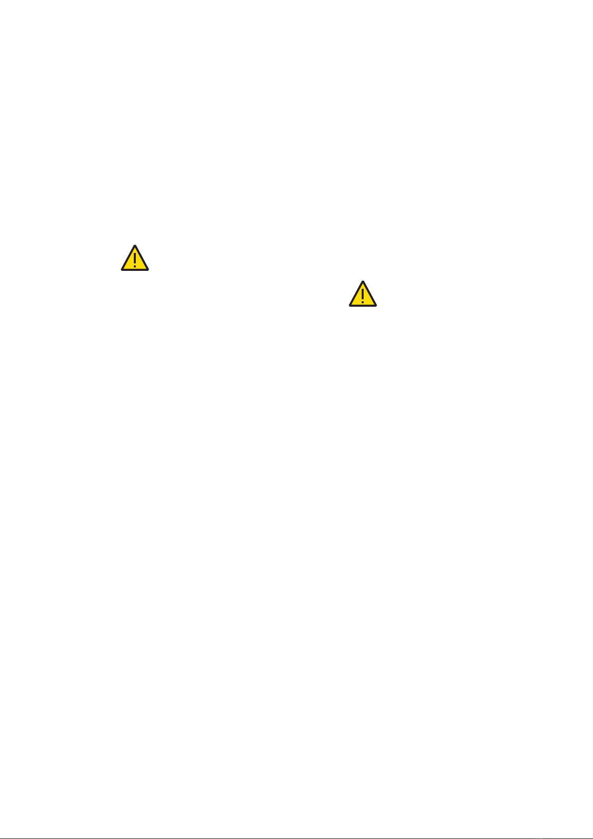
To handle the fixed parts containing the
apparatus (circuit breaker, contactor or
service truck), it is compulsory to use the
lifting eyebolts provided with the module.
4.1.1. Handling with bridge or mobile crane and
unpacking
Handling the fixed part in the wood packing
Lifting by means of a crane must be carried out using
the circular slings (1) (fig. 2).
The slings must be inserted according to the lifting
symbols marked on the crate.
Weight and lifting opening angle must be taken into
account when choosing the circular slings.
Unpacking
• Remove the nails and crate lid and sides;
• loosen the screws fixing the fixed part to the pallet
(if present);
• lift the module by means of the crane;
• slide the pallet out from under the fixed part;
• position the unloading shims;
• lower the module onto the shims using the crane.
After unpacking it, lift the module by means of a
crane, using the special eyebolts (1) (fig. 3) and the
ropes fitted with safety spring catches.
After installation, remove the eyebolts (1).
4.1.2. Handling by means of transpallets or fork
lift trucks
fork lift trucks run must be completely
which might turn it over.
For greater stability, only lift the fixed part enough to
allow handling. Also check levelness of the forks.

1
1
DISTRIBUTION SOLUTIONS 7
Handling the module in the wooden crate Module lifting
Lifting a fixed part packed in a wooden crate. Fixed part handling.
Fig. 2 Fig. 3
Fig. 4 Fig. 5

1
3
2
8PB/F - PB/FL type PowerCube - INSTALLATION AND SERVICE INSTRUCTIONS
5.1. Construction features
The fixed parts allow MV switchboards with metal
enclosure to be built, suitable for indoor installation.
The fixed parts are pre-assembled and tested in the
factory.
The fixed parts are suitable for all primary
distribution requirements with service voltages up to
24 kV and can take on different configurations
according to customer requests.
The fixed parts allow arc-proof switchboards to be
—
5. Description
constructed in compliance with the prescriptions of
the IEC 62271/200, Class of access (A) criteria (1 - 5).
With the PB/F fixed parts it is possible to build
switchgears with IP2X degree of protection with
open door.
Motorizable for PB1, PB2, PB3 and PB4/F-FL.
Each unit (fig. 6) is set up of:
1 Shutters
2 Lower and upper monoblocks
3 Earthing switch (on request)
Fig. 6

DISTRIBUTION SOLUTIONS 9
Un [kV] In [kA] Icw-Isc [A] Module
31.5 400 600mm PB1/F-PB1/FL
31.5 630 600mm PB1/F-PB1/FL
31.5 1250 600mm PB1/F-PB1/FL
31.5 630 750mm PB2/F-PB2/FL
31.5 1250 750mm PB2/F-PB2/FL
31.5 1600 750mm PB2/F-PB2/FL
31.5 2000 750mm PB2/F-PB2/FL
40 1200 750mm PB2/FL
40 2000 750mm PB2/FL
31.5 630 600mm PB1/F-PB1/FL
31.5 1250 600mm PB1/F-PB1/FL
31.5 630 750mm PB2/F-PB2/FL
31.5 1250 750mm PB2/F-PB2/FL
31.5 1600 750mm PB2/F-PB2/FL
31.5 2000 750mm PB2/F-PB2/FL
25 630 750mm PB4/F
25 1250 750mm PB4/F
40-50 1250 750mm PB2/F-PB2/FL
40-50 1600 750mm PB2/F-PB2/FL
40-50 2000 750mm PB2/F-PB2/FL
40-50 1250 750mm PB2/F-PB2/FL
40-50 1600 750mm PB2/F-PB2/FL
40-50 2000 750mm PB2/F-PB2/FL
5.2. Dimensions and weights
Types available
PowerCube PB1/F ... PB4/F and PB1/FL ... PB2/FL: suitable for incoming, outgoing and bus-tie units.

596
900
1033 28
1016
596
1015
787
10 PB/F - PB/FL type PowerCube - INSTALLATION AND SERVICE INSTRUCTIONS
—
5. Description
Overall dimensions
Dimensional drawings available on request in electronic format.
PB1/F PB1/FL
Un (kV) Icw (kA) In (A) TN
12 31.5 630-1250 1VCD003382
17 31.5 630-1250 1VCD003382
Un (kV) Icw (kA) In (A) TN
12 31.5 630-1250 1VCD003614
17 31.5 630-1250 1VCD003614
Typical use
Contact diameter (mm) 35mm
Rated voltage 12-17kV
Test voltage at industrial frequency 28-38kV
Impulse withstand voltage 75-95kVbil
Short-time withstand current 31.5kAx3s
Peak current 79kA
Rated branch current 630-1250A
Short-time withstand current 31.5kAx3s
Peak current 79kA

746
983
1015
1096
746 1033 28
1016
746
1226
1247
281310
DISTRIBUTION SOLUTIONS 11
PB2/F PB2/FL
Un (kV) Icw (kA) In (A) TN
12 50 630-2000 1VCD003383
17 50 630-2000 1VCD003383
Un (kV) Icw (kA) In (A) TN
12 50 630-2000 1VCD000210
15 40 1200-2000 1VCD000210
17 50 630-2000 1VCD000210
Typical use
Rated voltage 12-17kV
Test voltage at industrial frequency 28-38kV
Impulse withstand voltage 75-95kVbil
Short-time withstand current 40kAx3s-50kAx1s
Peak current 125kA
Rated branch current
630-1250A(1)
1600-2000A(2)
Short-time withstand current 31.5kAx3s-40÷50kAx1s
Peak current 79kA
(1) Contact diameter 35 mm.
(2) Contact diameter 79 mm.
PB4/F
Dimensional drawings available on request in electronic format.
Typical use
Rated voltage 15kV
Test voltage at industrial frequency 36kV
Impulse withstand voltage 95kV
Short-time withstand current 40kAx2s
Peak current 104kA
Rated branch current 1200-2000A(2)
Un (kV) Icw (kA) In (A) TN
24 31.5 630-1250 1VCD003384
Typical use
Rated voltage 24kV
Test voltage at industrial frequency 50kV
Impulse withstand voltage 125kVbil
Short-time withstand current 31.5kAx3s
Peak current 79kA
Rated branch current 630-1250A(1)
Earthing switch (if requested)
Short-time withstand current 31.5kAx3s
Peak current 79kA
(1) Contact diameter 35 mm.

12 PB/F - PB/FL type PowerCube - INSTALLATION AND SERVICE INSTRUCTIONS
—
5. Description
kV Isc
(kA)
Icw
(kA)
Circuit breaker PowerCube
16 16 630 VD4/P12.06.16p150 VD4/P17.06.16p150
20 20 630 VD4/P12.06.20p150 VD4/P17.06.20p150
25 25 630 VD4/P12.06.25p150 VD4/P17.06.25p150
31.5 31.5 630 VD4/P12.06.32p150 VD4/P17.06.32p150
16 16 1250 VD4/P12.06.16p150 VD4/P17.12.16p150
20 20 1250 VD4/P12.06.20p150 VD4/P17.12.20p150
25 25 1250 VD4/P12.06.25p150 VD4/P17.12.25p150
31.5 31.5 1250 VD4/P12.06.32p150 VD4/P17.12.32p150
16 16 630 VD4/W12.06.16p210 VD4/W17.06.16p210
20 20 630 VD4/W12.06.20p210 VD4/W17.06.20p210
25 25 630 VD4/W12.06.25p210 VD4/W17.06.25p210
31.5 31.5 630 VD4/W12.06.32p210 VD4/W17.06.32p210
16 16 1250 VD4/W12.12.16p210 VD4/W17.12.16p210
20 20 1250 VD4/W12.12.20p210 VD4/W17.12.20p210
25 25 1250 VD4/W12.12.25p210 VD4/W17.12.25p210
31.5 31.5 1250 VD4/W12.12.32p210 VD4/W17.12.32p210
40 40 1250 VD4/W12.12.40p210 VD4/W17.12.40p210
50 50 1250
40 40 1250 VD4/P12.12.40p210 VD4/P17.12.40p210
50 50 1250 VD4/P12.12.50p210 VD4/P17.12.50p210
20 20 1600 VD4/P12.16.20p210 VD4/P17.16.20p210
25 25 1600 VD4/P12.16.25p210 VD4/P17.16.25p210
31.5 31.5 1600 VD4/P12.16.32p210 VD4/P17.16.32p210
40 40 1600 VD4/P12.16.40p210 VD4/P17.16.40p210
50 50 1600 VD4/P12.16.50p210 VD4/P17.16.50p210
20 20 2000 VD4/P12.20.20p210 VD4/P17.20.20p210
25 25 2000 VD4/P12.20.25p210 VD4/P17.20.25p210
31.5 31.5 2000 VD4/P12.20.32p210 VD4/P17.20.32p210
40 40 2000 VD4/P12.20.40p210 VD4/P17.20.40p210
50 50 2000 VD4/P12.20.50p210 VD4/P17.20.50p210
40 40 1200 VD4/P15.12.40p210 −
40 40 2000 VD4/P15.20.40p210 −
16 16 630 VD4/P24.06.16p210 −
20 20 630 VD4/P24.06.20p210 −
25 25 630 VD4/P24.06.25p210 −
16 16 1250 VD4/P24.12.16p210 −
20 20 1250 VD4/P24.12.20p210 −
25 25 1250 VD4/P24.12.25p210 −
31.5 31.5 1250 VD4/P24.12.32p210 −
W = Width of PowerCube module.
P = Horizontal centre distance between circuit breaker poles.
u/l = Distance between top and bottom terminal.
H = Distance between bottom terminal and earth
Ø = Diameter of the contacts in the PowerCube module monobloc.
(*) The fixed parts are not prepared for application of the “motorised truck”.
Fixed parts compatibility with ABB apparatus
Table 1 - VD4 withdrawable circuit breakers (*)
Rated current of the circuit breakers VD4 (A - 40 °C)

DISTRIBUTION SOLUTIONS 13
kV Isc
(kA)
Icw
(kA)
Circuit breaker PowerCube
16 16 630 HD4/W12.06.16p150 HD4/W17.06.16p150
25 25 630 HD4/W12.06.25p150 HD4/W17.06.25p150
31.5 31.5 630 HD4/W12.06.32p150 HD4/W17.06.32p150
16 16 1250 HD4/W12.12.16p150 HD4/W17.12.16p150
25 25 1250 HD4/W12.12.25p150 HD4/W17.12.25p150
31.5 31.5 1250 HD4/W12.12.32p150 HD4/W17.12.32p150
16 16 630 HD4/W12.06.16p210 HD4/W17.06.16p210
25 25 630 HD4/W12.06.25p210 HD4/W17.06.25p210
31.5 31.5 630 HD4/W12.06.32p210 HD4/W17.06.32p210
16 16 1250 HD4/W12.12.16p210 HD4/W17.12.16p210
25 25 1250 HD4/W12.12.25p210 HD4/W17.12.25p210
31.5 31.5 1250 HD4/W12.12.32p210 HD4/W17.12.32p210
40 40 1250 HD4/W12.12.40p210 HD4/W17.12.40p210
50 50 1250 HD4/W12.12.50p210 HD4/W17.12.50p210
16 16 1600 HD4/W12.16.16p210 HD4/W17.16.16p210
25 25 1600 HD4/W12.16.25p210 HD4/W17.16.25p210
31.5 31.5 1600 HD4/W12.16.32p210 HD4/W17.16.32p210
40 40 1600 HD4/P12.16.40p210 HD4/P17.16.40p210
50 50 1600 HD4/P12.16.50p210 HD4/P17.16.50p210
16 16 2000 HD4/W12.20.16p210 HD4/W17.20.16p210
25 25 2000 HD4/W12.20.25p210 HD4/W17.20.25p210
31.5 31.5 2000 HD4/W12.20.32p210 HD4/W17.20.32p210
40 40 2000 HD4/P12.20.40p210 HD4/P17.20.40p210
50 50 2000 HD4/P12.20.50p210 HD4/P17.20.50p210
16 16 630 HD4/W24.06.16p210 −
20 20 630 HD4/W24.06.20p210 −
25 25 630 HD4/W24.06.25p210 −
16 16 1250 HD4/W24.12.16p210 −
20 20 1250 HD4/W24.12.20p210 −
25 25 1250 HD4/W24.12.25p210 −
31.5 31.5 1250 HD4/P24.12.32p210 −
W = Width of PowerCube module.
P = Horizontal centre distance between circuit breaker poles.
u/l = Distance between top and bottom terminal.
H = Distance between bottom terminal and earth
Ø = Diameter of the contacts in the PowerCube module monobloc.
Rated current of the circuit breakers HD4 (A - 40 °C)

14 PB/F - PB/FL type PowerCube - INSTALLATION AND SERVICE INSTRUCTIONS
—
5. Description
Rated current of the circuit breakers VM1 (A - 40 °C)
kV Isc
(kA)
Icw
Circuit breaker PowerCube
16 16 630 VM1/P12.06.16p150 VM1/P17.06.16p150
20 20 630 VM1/P12.06.20p150 VM1/P17.06.20p150
25 25 630 VM1/P12.06.25p150 VM1/P17.06.25p150
31.5 31.5 630 VM1/P12.06.32p150 VM1/P17.06.32p150
16 16 1250 VM1/P12.12.16p150 VM1/P17.12.16p150
20 20 1250 VM1/P12.12.20p150 VM1/P17.12.20p150
25 25 1250 VM1/P12.12.25p150 VM1/P17.12.25p150
31.5 31.5 1250 VM1/P12.12.32p150 VM1/P17.12.32p150
16 16 630 VM1/W12.06.16p210 VM1/W17.06.16p210
20 20 630 VM1/W12.06.20p210 VM1/W17.06.20p210
25 25 630 VM1/W12.06.25p210 VM1/W17.06.25p210
31.5 31.5 630 VM1/W12.06.32p210 VM1/W17.06.32p210
16 16 1250 VM1/W12.12.16p210 VM1/W17.12.16p210
20 20 1250 VM1/W12.12.20p210 VM1/W17.12.20p210
25 25 1250 VM1/W12.12.25p210 VM1/W17.12.25p210
31.5 31.5 1250 VM1/W12.12.32p210 VM1/W17.12.32p210
20 20 1600 VM1/P12.16.20p210 VM1/P17.16.20p210
25 25 1600 VM1/P12.16.25p210 VM1/P17.16.25p210
31.5 31.5 1600 VM1/P12.16.32p210 VM1/P17.16.32p210
20 20 2000 VM1/P12.20.20p210 VM1/P17.20.20p210
25 25 2000 VM1/P12.20.25p210 VM1/P17.20.25p210
31.5 31.5 2000 VM1/P12.20.32p210 VM1/P17.20.32p210
16 16 630 VM1/P24.06.16p210 −
20 20 630 VM1/P24.06.20p210 −
25 25 630 VM1/P24.06.25p210 −
16 16 1250 VM1/P24.12.16p210 −
20 20 1250 VM1/P24.12.20p210 −
25 25 1250 VM1/P24.12.25p210 −
W = Width of PowerCube module.
P = Horizontal centre distance between circuit breaker poles.
u/l = Distance between top and bottom terminal.
H = Distance between bottom terminal and earth
Ø = Diameter of the contacts in the PowerCube module monobloc.
(*) The fixed parts are not prepared for application of the “motorised truck”.

DISTRIBUTION SOLUTIONS 15
Rated current of the VM1/A/P contactors (A - 40 °C)
kV Isc
(kA)
Icw
Circuit breaker PowerCube
(IEC- compatible
version)
25 25 1250 VM1/A/P15.12.25p150
31.5 31.5 1250 VM1/A/P15.12.32p150
25 25 1200 VM1/A/W15.12.25p210
31.5 31.5 1200 VM1/A/W15.12.32p210
25 25 2000 VM1/A/P15.20.25p210
31.5 31.5 2000 VM1/A/P15.20.32p210
Rated current of the V-Contact contactors (A - 40 °C)
kV Isc
(kA) ()
Icw
Contactor PowerCube
16 6 400(2)
V S C 7/ P
20 6 400(2)
25 6 400(2)
31.5 6 400(2)
16 6 400(2)
VSC12/P
20 6 400(2)
25 6 400(2)
31.5 6 400(2)
(1) Guaranteed using suitable fuses.
(2) The rated current is subject to derating according to the rated current of the fuses.

16 PB/F - PB/FL type PowerCube - INSTALLATION AND SERVICE INSTRUCTIONS
—
5. Description
kV Isc
(kA) ()
Icw
Contactor PowerCube
16 6 400(2)
Co nVa c7/ P
20 6 400(2)
25 6 400(2)
31.5 6 400(2)
W = Width of fixed part.
P = Horizontal centre distance between circuit breaker poles.
u/l = Distance between top and bottom terminal.
H = Distance between bottom terminal and earth.
Ø = Diameter of the contacts in the PB type PowerCube unit monobloc.
(1) Guaranteed using suitable fuses.
(2) The rated current is subject to derating according to the rated current of the fuses.
kV Isc
Icw
(kA)
Rated current of the apparatus racked
into the fixed part
Apparatus which can be combined with
the fixed part
Type of apparatus PowerCube
25 25 1250 VD4G/P-2515.12.25p150 PB1/F
PB1/FL
40 40 1250 VD4G/P-4015.12.40p210
PB2/F
PB2/FL
40 40 1600 VD4G/P-4015.16.40p210
40 40 2000 VD4G/P-4015.20.40p210
40 40 2000 VD4G/P-4015.20.40p275
PB3/F
PB3/FL
40 40 3200 VD4G/W-4015.32.40p275
40 40 4000 VD4G/W-4015.40.40p275
50 50 3200 VD4G/W-5015.32.50p275
50 50 4000 VD4G/W-5015.40.50p275
W = Width of fixed part.
P = Horizontal centre distance between circuit breaker poles.
u/l = Distance between top and bottom terminal.
H = Distance between bottom terminal and earth
Ø = Diameter of the contacts in the PB type PowerCube unit monobloc.

DISTRIBUTION SOLUTIONS 17
5.3. Main components
5.3.1. Apparatus
PowerCube modules can be equipped with the
following apparatus:
• HD4 series SF6 circuit breaker;
• VD4, VM1 and eVD4 series vacuum circuit breaker;
• V-Contact VSC series vacuum contactor / ConVac;
• operational trucks;
• measurement trucks.
The apparatus is always the withdrawable version,
mounted on a truck that allows the following
positions in relation to the compartment:
CONNECTED: – main circuits connected;
ISOLATED: – partially isolated with main circuits
disconnected;
– totally isolated with main circuits
disconnected;
WITHDRAWN: – main circuits disconnected and
apparatus racked out.
The apparatus is equipped with special locks, located
on the front crosspiece which allow their hooking into
the corresponding slots of the unit. The front
hooking crosspiece also allows the connecting/
isolating , with the door closed, by means of the
special operating lever.
A lock prevents truck insertion (for example when the
earthingswitch is closed).
If the truck is in the indefinite position (between
connected and isolated), the lock prevents both
mechanical and electrical circuit breaker closing.
The truck can be equipped with a locking magnet
which, if deenergised, prevents its operation.
The connector (plug) for connection of the operating
mechanism electrical accessories comes out of the
front protection of the apparatus.
The slides for activating the segregation shutters of
the medium voltage contacts are placed on the sides
of the apparatus.
Please refer to the relative instruction booklet for
further details.

1 3
4
5 5
2
4
18 PB/F - PB/FL type PowerCube - INSTALLATION AND SERVICE INSTRUCTIONS
—
5. Description
Fig. 7
The certain position of the earthing switch
is indicated by the graphic symbols at the
operating seat (2). The position of the
earthing switch is indicated by the yellow
arrow made directly on the operating shaft
(5).
The position of the earthing switch can be
checked either by means of the indicator
(3), located inside the enclosure and visible
through the inspection window (4)
positioned on the bottom front part of the
unit.
The points of attachment of the grounding
connection to the earthing switch are
marked below the earthing switch by the
yellow plate bearing the earthing symbol.
5.3.2. Earthing switch
The earthing switch (1) (fig. 7) with making capacity
is placed in the fixed part rear side, whereas the front
houses the operating mechanism (2).
The switch position is indicated in the flange of the
operating seat (2).

8
27
16
11
12
7 9 10
15
15
16
18
DISTRIBUTION SOLUTIONS 19
Fig. 8
5.3.3. Fixed part description
The metal structure is fitted with operating and
control mechanisms on the external front side (fig. 8).
The earthing switch control panel on the lower front
part is fitted with:
• the earthing switch operating mechanism seat (10);
• the actuator (9) for operating the shutter (11) of the
earthing switch operating mechanism seat;
• key lock (on request) with free key at earthing
switch open (8);
• key lock (on request) with free key at earthing
switch closed (12);
• key lock (on request) with free key for preventing
apparatus racking in (7).
The fixed part houses the following components:
• truck guides (15);
• segregating shutters (18) of the fixed isolating
contacts inside the monoblocks and the shutter
operating mechanisms (16);
• mechanical lock for preventing either circuit breaker
racking in when the earthing switch is closed or
earthing switch closing if the circuit breaker is
connected (27).
The insulating monoblocks (14) for the power
connections are on the rear of the fixed part.

20 PB/F - PB/FL type PowerCube - INSTALLATION AND SERVICE INSTRUCTIONS
—
5. Description
The locks used in the fixed parts are mechanical and
electrical with microswitches for circuit continuity or
interruption.
The mechanical locks are divided into:
• force locks;
• prevention locks;
• electromechanical locks;
• safety locks (padlocks/keys).
PowerCube modules can be equipped with the locks
shown in the following table.
normal operating force (not more than
200 N) only using the special levers.
Should the operations be prevented, do
not force the mechanical interlocks and
check that the operations are correct.
maximum force of 400 N, using the
special operating tools.
5.4. Interlocks/locks
Lock description Apparatus Fixed part
Electric lock to prevent apparatus closing when the
truck is not in the connected/isolated position. (fig.10c-det.44)
Mechanical lock to prevent apparatus racking in/out in
the closed position, and closing when the truck is not in
the connected and isolated positions.
Locking electromagnet on the apparatus truck to
prevent racking-in/out without power. (fig.10c-det.43)
Mechanical interlock with earthing switch:
– the apparatus cannot be inserted when the earthing
switch is closed;
– the earthing switch cannot be closed when the
apparatus is inserted or in the intermediate positions
between connected and isolated.
(fig.10a-det.12)
(fig.9-det.1)
Mechanical lock to prevent the manual opening of the
shutters when the apparatus is withdrawn (Fail-Safe). (fig.10b-det.3) (fig.9-det.2)
Key lock to prevent apparatus insertion. Only when the
apparatus is in the isolated position can the lock be
operated and the key released thus preventing
apparatus insertion.
(fig.9a-det.3)
Key lock with open earthing switch. It can only be
operated when the earthing switch is open. The key can
only be withdrawn with the lock activated.
(fig.9a-det.4)
Key lock with closed earthing switch. It can only be
operated when the apparatus is isolated and the
earthing switch is closed. The key can only be
removed with the lock activated.
(fig.9a-det.5)
Holes for padlock of the shutters in the closed position
(Padlockdiameter4mm). (fig.9a-det.6)
Earthing switch electromechanical lock to prevent
earthing switch opening and closing once the coil (BED)
is de-energised.
(fig.9a-det.7)
Padlock lock to prevent manual apparatus closing.
Standard
On request.
Other manuals for PowerCube PB/F
1
This manual suits for next models
1
Table of contents
Other ABB Industrial Equipment manuals