Lochinvar LOKE8-50 Guide

1
Models
LOKE8-50
LOKE8-75
LOKE8-100
LOKE8-125
LOKE8-150
LOKE8-175
LOKE8-200
LOKE8-225
LOKE8-250
LOKE
Instantaneous packaged plate heat exchanger
Installation, Commissioning, Maintenance
and User instructions
installation manual_LOKE_November 2020

2
BLANK PAGE

3
TABLE OF CONTENTS
Contents
1.0 INTRODUCTION............................................................................................................................................... 4
ANCILLARY OPTIONS...................................................................................................................................................4
2.0 SAFETY GUIDELINES......................................................................................................................................... 4
GENERAL DESCRIPTION OF SAFETY SYMBOLS USED......................................................................................................5
3.0 SIZING AND SELECTION .................................................................................................................................... 5
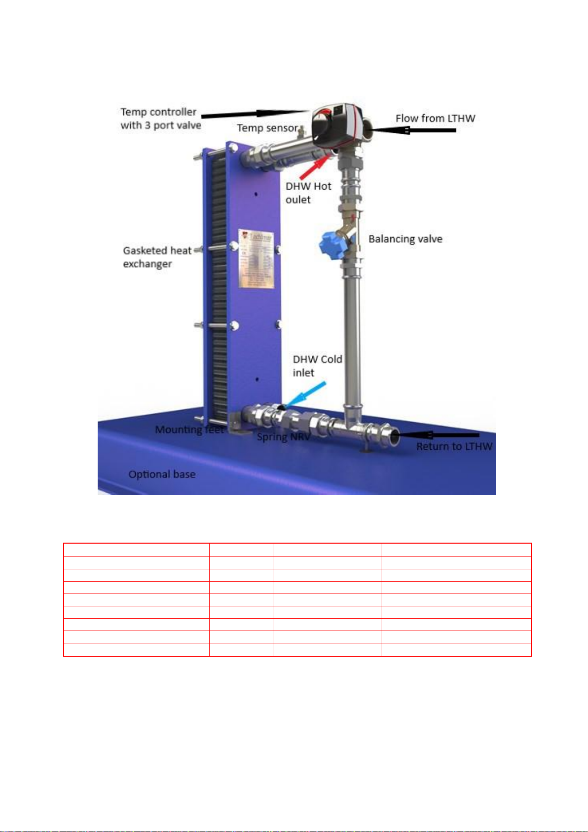
4.0 PRINCIPAL PARTS ............................................................................................................................................ 6
5.0 CONTROLLER .................................................................................................................................................. 6
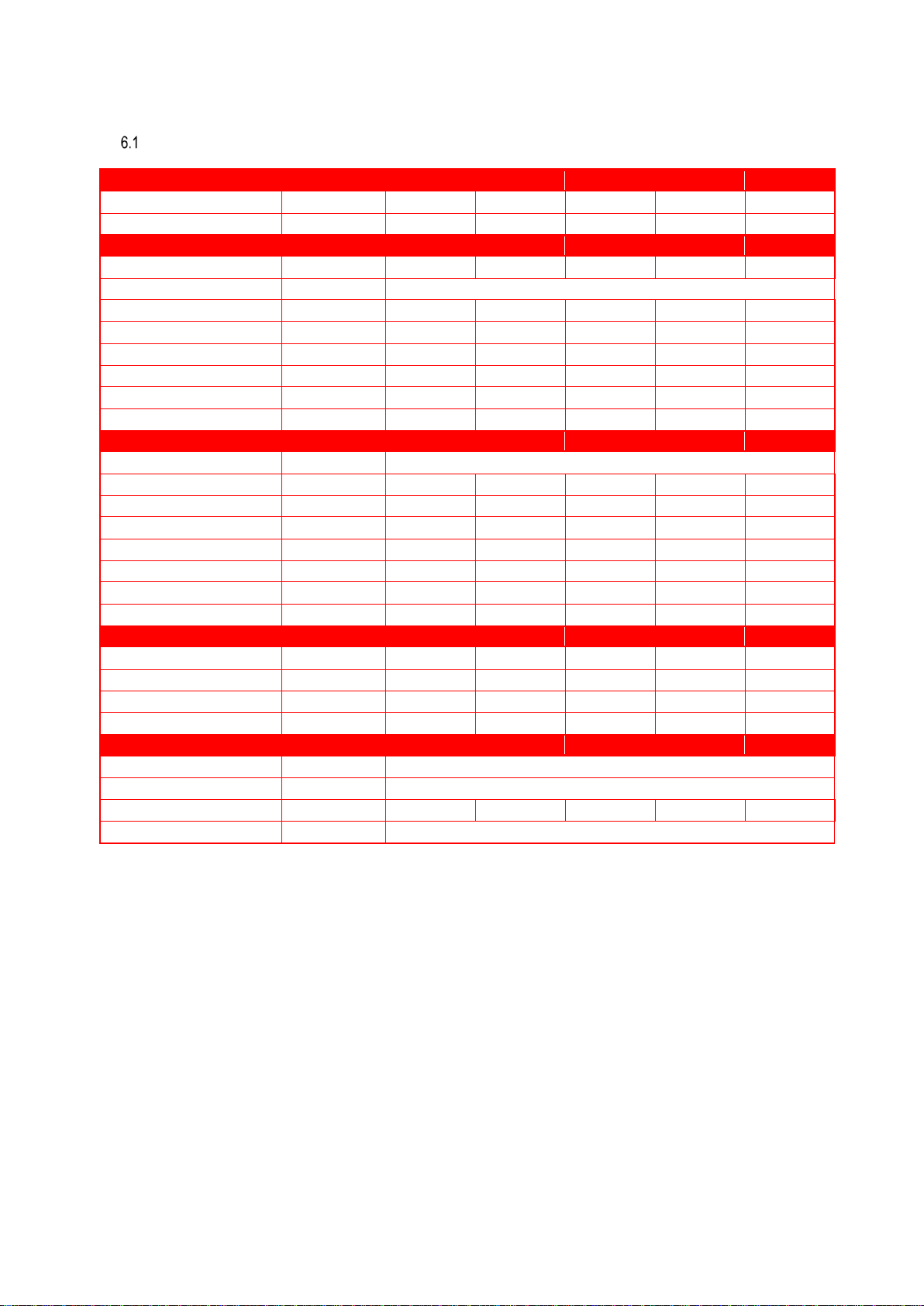
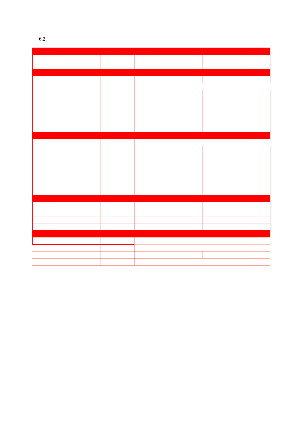
6.0 TECHNICAL DATA ............................................................................................................................................ 7
MODELS LOKE8-50 TO LOKE8-150................................................................................................................................7
MODELS LOKE8-200 TO LOKE8-250..............................................................................................................................8
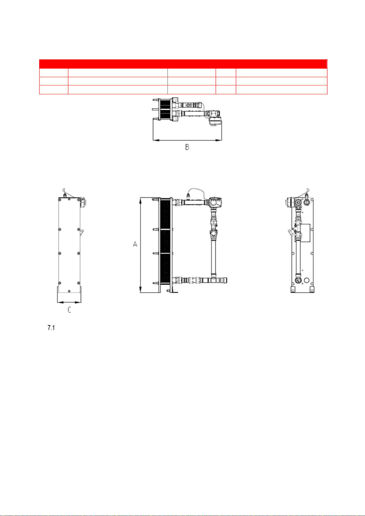
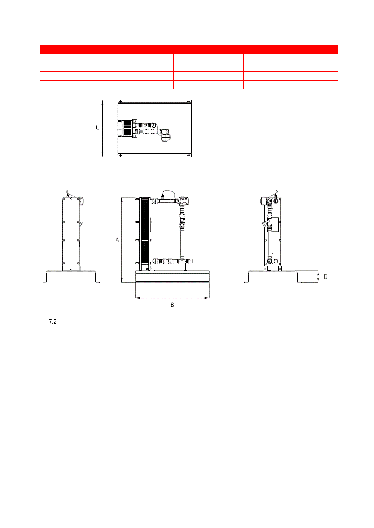
7.0 DIMENSIONS AND CLEARANCE.......................................................................................................................... 9
DIMENSIONS OF UNIT WITHOUT OPTIONAL BASE ........................................................................................................9
DIMENSIONS OF UNIT WITH OPTIONAL BASE FITTED..................................................................................................10
CLEARANCES ............................................................................................................................................................11
8.0 INSTALLATION ...............................................................................................................................................12
GENERAL REQUIREMENTS.........................................................................................................................................12
RELATED DOCUMENTS..............................................................................................................................................12
WATER QUALITY.......................................................................................................................................................12
LOCATION ................................................................................................................................................................12
LIFTING ....................................................................................................................................................................13
WATER CONNECTIONS..............................................................................................................................................13
UN-VENTED SYSTEM ARRANGEMENT ........................................................................................................................13
STANDARD UN-VENTED KITS .....................................................................................................................................14
CIRCULATING PUMPS................................................................................................................................................14
CONTROL .................................................................................................................................................................14
OVERHEAT PROTECTION ...........................................................................................................................................14
9.0 SCHEMATICS..................................................................................................................................................15
KEY FOR SCHEMATICS ...............................................................................................................................................15
10.0 ELECTRICAL SUPPLY ........................................................................................................................................18
ELECTRICAL SUPPLY REQUIREMENTS.........................................................................................................................18
EXTERNAL CONTROLS ...............................................................................................................................................18
11.0 COMMISSIONING AND TESTING.......................................................................................................................19
WATER CONNECTIONS..............................................................................................................................................19
TEMPERATURE ADJUSTMENT PROCEDURE ................................................................................................................19
12.0 MAINTENANCE ..............................................................................................................................................20
MAINTENANCE SCHEDULE ........................................................................................................................................20
DRAINING DHW WATER SYSTEM ...............................................................................................................................20
REFILLING THE SYSTEM .............................................................................................................................................20
RELIEF VALVE............................................................................................................................................................20
CLEANING PLATE GASKETS ........................................................................................................................................21
ASSEMBLY ................................................................................................................................................................21
PROCEDURE .............................................................................................................................................................22
13.0 FAULT FINDING ..............................................................................................................................................24
HEAT EXCHANGER PLATE PACK ASSEMBLY.................................................................................................................24
EXCESSIVE PRESSURE DROPS.....................................................................................................................................24
LEAKAGE ..................................................................................................................................................................24
DECREASE IN THE PERFORMANCE..............................................................................................................................24
14.0 DECLARATION OF CONFORMITY.......................................................................................................................25

4
1.0 INTRODUCTION
The Lochinvar LOKE Instantaneous packaged plate heat exchanger is designed to heat domestic hot water (DHW) using low
temperature hot water (LTHW) from a boiler or similar. The unit is designed with a low return temperature during demand to ensure
boilers are in continuous condensing mode.
LTHW is supplied to the unit from the low loss header by a primary DHW pump at the design flow rate as shown in the Technical
data table according to the model being fitted.
The primary DHW pump is not supplied with the unit.
When there is a DHW demand the three-port control valve modulates to allow LTHW to be pumped through the plate heat exchanger
providing DHW at the required set point.
The temperature of the DHW outlet is monitored at the fixed sensor on the DHW outlet pipe, this will send a signal to the controller
which then modulates the control valve maintaining setpoint.
ANCILLARY OPTIONS
•Unvented system kit
oCLK3520 for use with Models LOKE8-50 to LOKE8-150
oCOLK3503 for use with Models LOKE-175 to LOKE8-250
•Direct storage vessels with matched primary circulation pumps
For units being installed with a storage vessel contact Lochinvar Limited Internal Sales for a suitable
unvented kit
•Heat exchanger insulation jacket
•Skid mounting base
2.0 SAFETY GUIDELINES
READ AND UNDERSTAND THE INSTRUCTIONS
Read and fully understand all instructions before attempting to operate maintain or install the unit.
Keep these instructions near the water heater for quick reference.
This equipment must be installed by a competent person. All installations must
conform to the relevant Building Regulations.
Health & Safety requirements must also be considered when installing any equipment. Failure to comply with the above may lead
to prosecution
Without written approval of the manufacturer the internals of the water heater may not be changed. When
changes are executed without approval, the water heater certification and warranty becomes invalid.
Commissioning, maintenance and repair must be done by a skilled installer/engineer, according to all applicable standards and
regulations.

5
GENERAL DESCRIPTION OF SAFETY SYMBOLS USED
BANNED
A black symbol inside a red circle with a red diagonal indicates an action that should not be performed
WARNING
A black symbol added to a yellow triangle with black edges indicates danger
ACTION REQUIRED
A white symbol inserted in a blue circle indicates an action that must be taken to avoid risk
ELECTRICAL HAZARD
Observe all signs placed next to the pictogram. the symbol indicates components of the unit and
actions described in this manual that could create an electrical hazard.
HOT SURFACES
The symbol indicates those components with a high surface temperature that could create a risk.
This symbol shows essential information which is not safety related
Recover or recycle material
Lochinvar Limited is not liable for any damage caused by inaccurately following these installation
instructions. Only original parts may be used when carrying out any repair or service work.
This appliance is not intended for use by persons (including children) with reduced physical, sensory or
mental capabilities, or lack of experience and knowledge, unless they have been given supervision or
instruction concerning use of the appliance by a person responsible for their safety. Children MUST be
supervised to ensure that they do not play with the appliance.
3.0 SIZING AND SELECTION
LOKE package plate heat exchangers are an instantaneous type water heater; maximum flow rates can be found in the technical
data tables. If there is a chance the peak demand could temporarily exceed the maximum flow rate of the unit chosen, then
consideration should be given to using a small buffer vessel to cope with this peak flow.
For help with sizing and selection please contact your local Area Sales Manager or Lochinvar Internal Sales.

6
4.0 PRINCIPAL PARTS
5.0 CONTROLLER
Ambient temperature Max
+55C
Sensor
Type NTC
Ambient temperature Min
-5C
Enclosure rating
IP41
Temperature range
+5 to + 95C
Power supply
230V /1Ph/ 50hz
Protection class
II
Torque
6Nm
Power consumption
230v AC: 10VA
Connection, mounting set
External thread
Running time at maximum speed
30seconds
Supplied parts
Actuator with pre-assembled sensor
Material
Adapter kit for valve
Flow pipe sensor
stainless steel
Mounting set for sensor
Mounting set for flow pipe sensor
DZR Brass
230v AC transformer with UK Plug

7
6.0 TECHNICAL DATA
MODELS LOKE8-50 TO LOKE8-150
Output
Unit
LOKE8-50
LOKE8-75
LOKE8-100
LOKE8-125
LOKE8-150
Heat Transfer Duty
kW
50
75
100
125
150
Thermal efficiency
%
99.5
99.5
99.5
99.5
99.5
Primary Side
Inlet Temperature
°C
75
75
75
75
75
Outlet Temperature
°C
Varies Depending on Demand (40 At Full Demand)
Fluid Flow Rate
litre/second
0.34
0.51
0.68
0.85
1.03
Fluid type
Water
Water
Water
Water
Water
pressure drop
bar
0.21
0.28
0.27
0.31
0.28
Connection size and type
Inch BSPT
1"
1"
1"
1"
1¼"
Max Working Temperature
°C
100
100
100
100
100
Maximum Working Pressure
bar
10
10
10
10
10
Secondary Side
Inlet Temperature
°C
Varies Depending on Demand (10 At Full Demand)
Outlet Temperature
°C
65
65
65
65
65
Fluid Flow Rate
litres/second
0.22
0.33
0.43
0.54
0.65
Fluid type
Water
Water
Water
Water
Water
pressure drop
bar
0.11
0.11
0.11
0.12
0.12
Connection size and type
Inch BSPT Male
1"
1"
1"
1"
1¼"
Max Working Temperature
°C
95
95
95
95
95
Maximum Working Pressure
bar
10
10
10
10
10
Performance
Recovery Rate @ 55°C ∆T
litres/hour
792
1188
1548
1944
2340
Recovery Rate @ 55°C ∆T
litres/second
0.22
0.33
0.43
0.54
0.65
Recovery Rate @ 50°C ∆T
litres/hour
871
1307
1703
2138
2574
Recovery Rate @ 50°C ∆T
litres/second
0.24
0.36
0.47
0.59
0.72
General
Plate Material
AISI 316 Stainless Steel
Gasket Material
EPDM - Clip On
Empty weight
kg
53
65
67
69
70
Electrical Requirements
230V /1Ph/ 50hz

8
MODELS LOKE8-200 TO LOKE8-250
Output
Unit
LOKE8-175
LOKE8-200
LOKE8-225
LOKE8-250
Heat Transfer Duty
kW
175
200
225
250
Thermal efficiency
%
99.5
99.5
99.5
99.5
Primary Side
Inlet Temperature
°C
75
75
75
75
Outlet Temperature
°C
Varies Depending on Demand (40 At Full Demand)
Fluid Flow Rate
litre/second
1.2
1.37
1.54
1.71
Fluid type
Water
Water
Water
Water
pressure drop
bar
0.3
0.33
0.35
0.38
Connection size and type
Inch BSPT
1¼"
1¼"
1¼"
1¼"
Max Working Temperature
°C
100
100
100
100
Maximum Working Pressure
bar
10
10
10
10
Secondary Side
Inlet Temperature
°C
Varies Depending on Demand (10 At Full Demand)
Outlet Temperature
°C
65
65
65
65
Fluid Flow Rate
litres/second
0.76
0.87
0.98
1.09
Fluid type
Water
Water
Water
Water
pressure drop
bar
0.12
0.12
0.12
0.11
Connection size and type
Inch BSPT Male
1¼"
1¼"
1¼"
1¼"
Max Working Temperature
°C
95
95
95
95
Maximum Working Pressure
bar
10
10
10
10
Performance
Recovery Rate @ 55°C ∆T
litres/hour
2736
3132
3528
3924
Recovery Rate @ 55°C ∆T
litres/second
0.76
0.87
0.98
1.09
Recovery Rate @ 50°C ∆T
litres/hour
3010
3445
3881
4316
Recovery Rate @ 50°C ∆T
litres/second
0.84
0.96
1.08
1.20
General
Plate Material
AISI 316 Stainless Steel
Gasket Material
EPDM - Clip On
Empty weight
kg
72
74
77
79
Electrical Requirements
230V /1Ph/ 50hz

9
7.0 DIMENSIONS AND CLEARANCE
Unit
Dimension
A
Total Height
mm
835
B
Depth
mm
710
C
Width
mm
196
DIMENSIONS OF UNIT WITHOUT OPTIONAL BASE

10
Unit
Dimension
A
Total Height
mm
965
B
Depth
mm
800
C
Width
mm
620
D
Base Depth
mm
130
DIMENSIONS OF UNIT WITH OPTIONAL BASE FITTED

11
CLEARANCES
•Unit shown with optional base fitted, if unit does not have optional base clearances are from side of plate pack.
•Side clearances can be reduced but the unit may need to be removed in the future if the plate pack requires replacing or
cleaning

12
8.0 INSTALLATION
GENERAL REQUIREMENTS
The LOKE water heater has been designed to operate trouble free for many years. These instructions should be followed closely to
obtain the maximum usage and efficiency of the equipment.
RELATED DOCUMENTS
The installation of the equipment MUST be in accordance with the relevant requirements Building Regulations, I.E.E. Regulations
and the bylaws of the local water undertaking.
In addition, the installation should follow the relevant guidance offered in the following documents. It is not practical to list all relevant
information, but emphasis is placed on the following documents, as failure to comply with the guidance given will almost certainly
result in an unsatisfactory installation:
Regulation
Description
BS EN 806 1-5
Specifications for installations inside buildings conveying water for human consumption.
BS 7671 :2008 + A3:2015
Code of practice for low temperature hot water systems of output greater than 45 kW.
BS 7074: 1989 Parts 1 and 2
Application, selection and installation of expansion vessels and ancillary equipment for
sealed systems.
BS 7671: 2008 + A1: 2011
Requirements for electrical installations, I.E.E. wiring regulations seventeenth edition.
BS 7671: Amendment 2: August
2013
BS EN 12828:2012+A1:2014
Heating systems in buildings. Design for water-based heating systems.
CIBSE: Guides
Part A Environmental Design
Part G Public health engineering
H.S.E. guidance
SAFED BG01Guidance on safe operation of Water Heaters
Manufacturer's notes must not be taken in any way as overriding statutory obligations.
WATER QUALITY
Water supply quality may adversely affect the efficiency performance and longevity of Water Heaters and Hot Water systems. Hard
water may cause the formation of lime scale which will reduce operating efficiency and may cause early product failure. Please note
the following: -
•Water Hardness –should not exceed 205ppm CaCO3 and Total Dissolved Solids (TDS) of untreated water should not
exceed 350ppm.
If these values are exceeded a water treatment specialist should be consulted. Water Softeners and Water Conditioners
may be considered, but whichever method is selected, it should be suitable for installation with Direct Gas-fired Water
Heaters. A maintenance regime will also be required for such systems
•High hot water temperature and high demand for hot water is likely to cause quicker limescale formation
The formation of limescale or other solids can cause a blockage within the heat exchanger, which in turn
may cause premature failure. Such instances are not regarded as defects in manufacture and will not be
covered under the product warranty.
LOCATION
The equipment must be installed on a level surface that is capable of adequately supporting its weight (when
filled with water) and any ancillary equipment.
Locate the equipment so that if the appliance or any connecting pipework should leak, water damage will
not occur. When such locations cannot be avoided it is recommended that a suitable drain pan be installed
under the equipment. The pan should be adequately drained.

13
LIFTING
Always exercise extreme caution when lifting to avoid damage, lift from underneath on a pallet or base if
fitted
Avoid lifting from any of the pipework, controller, or valves
WATER CONNECTIONS
Do not weld near to or on the heat exchanger or associated components.
Use two wrenches when attaching unions to the domestic water circuit threaded stub connections. One wrench to be used to tighten
the union & the other to prevent the stub end from rotating –this avoids damage to the gasket inside the unit that seals against the
back on the stub connection. Use a none hardening thread sealant for best results. Threads are BS21 –taper, male. It is necessary
to support the secondary pump and the pipe work as the heat exchanger connections are not designed to accept any weight being
imposed upon them.
To avoid damage to the unit, to prevent failure and to ease maintenance, we recommend the following:
•Pipe-work - fully support to avoid weight/forces acting upon the unit / connections.
•The fitting of flexible couplings if the pipe work is subject to vibration.
•The pipe work is completely flushed before attaching to exchanger. The exchanger acts as an effective filter and will
become blocked if pipe-work debris can enter the plate pack.
•The fitting of suitable vents, isolation valves & drains. To allow servicing of the package without complete system draining
appropriate isolation valves should be fitted.
•The fitting of non-return valves where appropriate
•The fitting of suitable sized pressure relief valves in the pipe work on both circuits (essential safety requirement).
The LOKE must be installed as per the schematics here, failure to include all necessary valves etc. Will
invalidate the warranty and could lead to a dangerous situation on site.
UN-VENTED SYSTEM ARRANGEMENT
If the LOKE is to be used in an unvented arrangement, the system should follow the guidance given in BS6700 and must comply
with The Building Regulations: Part G3 in England and Wales, P5 in Northern Ireland and P3 in Scotland. A kit of components
that have been suitably sized for the unvented or boosted operation of the appliance is available from Lochinvar Limited. For further
information, see below.

14
STANDARD UN-VENTED KITS
LOK Model
Part Number
Description
QTY
LOKE8-50 TO
LOKE8-150
CLK3520
22MM MONOBLOC INLET CONTROLS INCLUDES;
1
NON-RETURN VALVE
PRESSURE REDUCING VALVE - 3 TO 6 BAR
6 BAR PRESSURE RELIEF VALVE
LOKE8-175 TO
LOKE8-250
COLK3503
28MM MONOBLOC INLET CONTROL INCLUDES:
1
• NON-RETURN VALVE
• PRESSURE REDUCING VALVE 3 TO 6 BAR
• 6 BAR PRESSURE RELIEF VALVE
8.8.1 EXPANSION VESSEL SIZING
The following information is based on an inlet pressure of 3.5 bar and an expansion vessel efficiency of 0.45 using a standard 6 bar
unvented kit. If the system will have different parameters a more detailed calculation will need to be made.
V V = S V * e
0.45
Where:
V V = Vessel Volume
S V = System Volume
e = Coefficient of Expansion
Stored Temp.
C
30
35
40
45
50
55
60
e
0.005
0.006
0.008
0.010
0.012
0.015
0.017
Stored Temp.
C
65
70
75
80
82
85
90
e
0.020
0.023
0.026
0.030
0.031
0.033
0.037
CIRCULATING PUMPS
The LOKE will require a suitably sized DHW primary pump sized to match the required flowrate and overcome the plate pressure
drop details can be found in the technical data table.
CONTROL
The controller is factory fitted to the three-port valve.
OVERHEAT PROTECTION
Due to its simple design the LOKE does not feature an overheat cut-off, in order to fully comply with Building regulation G3 and to
prevent a scalding risk downstream at the outlets a suitable second form of protection must be installed after the outlet from the unit.
Depending upon whether the LOKE has been fitted with or without a storage vessel there are several options available to installers:
1. Fitting a suitable tempering valve on the hot outlet will prevent temperatures exceeding that set at the tempering valve.
2. Fitting a two-port valve on the primary pipework connected to a strap on sensor on the DHW side, this will close preventing
further heat transfer.
3. If installed with a storage vessel a suitable thermostat fitted to the store could close a two-port valve fitted on the primary
pipework.
See schematics for further information.
To comply with Building regulation G3 a suitable second form of temperature protection must be fitted to
the system, this second form of protection is not supplied with the unit.

15
9.0 SCHEMATICS
KEY FOR SCHEMATICS
Lochinvar limited may provide technical advice and guidance to assist with best practice, optimisation and
installation of Lochinvar products; however, we will not be liable for any duties as designers under
construction (design and management regulations 2015). In all cases where information is provided, the
customer must assess and manage risks associated with the technical information and advice provided.
SYMBOL
DESCRIPTION
IV
ISOLATION VALVE
LSV
LOCKSHIELD VALVE
TPRV
TEMPERATURE AND PRESSURE RELEIF VALVE
TD
TUNDISH
EXV
EXPANSION VESSEL
EV
EXPANSION VALVE
PRV
PRESSURE REDUCING VALVE
NRV
NON-RETURN VALVE
TS
TEMPERATURE SENSOR (VESSEL SENSOR)
BRP
BUILDING RETURN PUMP
PMP
PRIMARY CIRCULATING PUMP
RLY
RELAY
TV
TEMPERING VALVE
TS
TEMPERATURE SENSOR

16
Schematic LOKE instantaneous installation

17
Schematic LOKE with storage vessel-schematic

18
10.0 ELECTRICAL SUPPLY
Wiring external to the equipment must be installed in accordance with the I.E.E. Regulations and any local regulations that
apply.
ELECTRICAL SUPPLY REQUIREMENTS
Warning: this appliance must be earthed
A suitably competent person must check wiring. Normal supply required is 230 volts’ AC, single phase,
50hz. An isolator with a contact separation of at least 3mm in all poles should be sited close to the
equipment and must only serve that equipment. The double pole switch must be readily accessible
under all conditions
The controller fitted to the three-port valve simply plugs into a standard UK plug socket, alternatively the plug can be removed, and
the controller hard wired into a junction box.
EXTERNAL CONTROLS
There are no external control options with the LOKE unit, if a unit is required with BMS control options a standard LOK unit should
be used, contact Lochinvar Internal sales for more information.

19
11.0 COMMISSIONING AND TESTING
WATER CONNECTIONS
See Section 8.6: WATER CONNECTIONS
The system should be thoroughly flushed out with cold water without any circulating pumps in position.
Ensure all the valves are open.
Check the system for leaks and repair as necessary. If the system is configured in a sealed arrangement, check the expansion
vessel cushion pressure and pressurisation unit settings.
TEMPERATURE ADJUSTMENT PROCEDURE
Once filled with water, and before use, or if the system has been drained down for a period of time, it is important to check the
operation of the valve –switch on the controller and set the temperature to a high level (temperature altered by raising the set point).
The actuator should slowly rotate until the valve is at the fully diverting position and then stop. Now lower the temperature (below
ambient), and the actuator should rotate anti-clockwise and stop at around the fully open position.
If the actuator does not move, or does not turn full travel, then switch off at the panel, the controller is not functioning correctly and
will need to be investigated further.
11.1.1 SETTING/CHANGING TEMPERATURE SET POINT
Ensure controller is plugged in or the junction box turned on if hard wired.
A= To change setpoint move joystick to either the left or right
B= Press joystick down to confirm new setpoint
11.1.2 SETTING MIN/MAXIMUM FLOW TEMPERATURES
A=Press joystick and hold for five seconds
B=Choose menu Max or Min
C=Select OK
D=Adjust setting by scrolling with the joystick
C=Select OK
A=Press down joystick and hold for five seconds to return to main menu

20
12.0 MAINTENANCE
MAINTENANCE SCHEDULE
Time Interval
Once a year as a minimum, every six months in hard water areas.
Performance
Check temperature and flow against commissioing data.
Plate pack
Check the tightening dimension, and look for any signs of leakage from heat exchanger.
Connections
Check general condition, and for any signs of leakage.
Frame
Wipe clean all painted parts, and check surfaces for signs of damage - “touch up” if necessary.
Bolts & bars
Check for rust, and clean. Lightly coat threaded parts with molybdenum grease, or a
corrosion inhibitor (ensure that no grease, etc. falls onto the plate gaskets).
Electrical
Check the security of all electrical connections and inspect the wiring for damage.
DRAINING DHW WATER SYSTEM
The LOKE and associated storage vessel (if fitted) must be drained if it is to be shut down and exposed to freezing temperatures.
Maintenance and service procedures may also require draining the water heater.
1. Unplug or turn off the LOKE electrical disconnect switch.
2. Connect a hose to the system drain valve.
3. Locate hose’s discharge in an area where hot water will not cause any damage or injury.
4. Close the cold-water inlet valve from the header tank or unvented kit unit to water heater system.
5. Open the drain valve.
6. Working systematically from the highest point in the system, open outlets to allow the system to drain.
7. Close all outlets.
8. If the water heater is being drained for an extended shutdown, it is suggested the drain valve be left open during this
period.
Note: The heat exchanger cannot be completely drained of water
REFILLING THE SYSTEM
1. Close the drain valve.
2. Open the cold-water inlet valve from the header tank or unvented kit to the water heater system.
3. Working systematically towards the highest point in the system, open all outlets and allow any trapped air to escape.
4. Follow the commissioning instructions as detailed in commissioning and testing.
5. Check for water leakage and airlocks, remedy as necessary.
RELIEF VALVE
At least once a year, the pressure relief valve should be checked to ensure correct operation. To check the valve, the manual
override lever should be operated several times. The valve should seat properly and operate freely.
If water does not flow, drain the water heater, remove the inoperative valve and inspect for obstructions or corrosion. Replace with
a new valve of equivalent size as necessary.
This manual suits for next models
8
Table of contents
Popular Industrial Equipment manuals by other brands

MATO
MATO pneuMATO 55 Lube-Jet operating instructions

ABB
ABB A165-L37 Operation manual

Festool
Festool VAC SYS SE Original operating manual/spare parts list

Nidec
Nidec LEROY-SOMER TAL 0473 Installation and Maintenance

Engel
Engel TDF HB-1640 Installation, operation & maintenance manual

ABB
ABB HT568590 Operation manual