Harris Constellation User guide

Microwave Digital Radios
Constellation®
Systems Application
P/N SAI-112874-E09


CONSTELLATION®
MICROWAVE RADIO
SYSTEM APPLICATION MANUAL
PART NO. SAI-112874-E09
JANUARY 2006

Constellation® January 2006

Harris Corporation Constellation®
Revision history
Issue date Status Description of change / revision
January 2006 PCO 25195 • Periodic update
Part Nº SAI-112874-E09
© Copyright 2006 HARRIS CORPORATION. All rights reserved.
Constellation®, FARSCAN™, and STARVIEW™are trademarks of
HARRIS CORPORATION
Data subject to change without notice.
Harris Corporation -
Microwave Communications Division
637 Davis Drive
Morrisville, NC 27560
U.S.A.
1-800-227-8332
FAX: 1-919-767-3233
Harris Corporation -
Microwave Communications Division
3, rue de l’Hôtel de Ville
Dollard-des-Ormeaux, Québec,
Canada H9B 3G4
1-800-227-8332 or 1-514-421-8400
FAX: 1-514-421-3555

Constellation® January 2006
WARNING
Making adjustments and/or modifications to this equipment that are not in
accordance with the provisions of this instruction manual or other
supplementary documentation may result in personal injury or damage to
the equipment, and may void the equipment warranty.
AVERTISSEMENT
Tout réglage ou modification faits à cet équipement hors du cadre édicté
par ce guide d’utilisation ou par toute autre documentation supplémentaire
pourraient causer des blessures ou endommager l’équipement et peut
entraîner l’annulation de sa garantie.
WARNUNG
Die an diesen Geräten gemachte Einstellungen und/oder Änderungen,
welche nicht gemäß dieser Bedienungsanleitung, oder gemäß anderen
zusätzlichen Anleitungen, ausgeführt werden, können Verletzungen oder
Materialschäden zur Folge haben und eventuell die Garantie ungültig
machen.
ATENCIÓN
Llevar a cabo ajustamientos y/o modificaciones a este equipo, sin seguir
las instrucciones provistas por este manual u otro documento adicional,
podría resultar en lesiones a su persona o daños al equipo, y anular la
garantía de este último.

Harris Corporation Constellation®
CONTENTS
CONTENTS
LIST OF FIGURES ................................................................V
LIST OF TABLES............................................................... VII
PREFACE ..........................................................................IX
ISO 9001 Certification ..................................................................................ix
Technical Assistance Center ..........................................................................ix
CHAPTER 1, GENERAL INFORMATION .................................. 1-1
Introduction ................................................................................................ 1-1
The Constellation Radio ................................................................................ 1-1
Interfaces ................................................................................................ 1-1
Standard Features .................................................................................... 1-2
Optional Features ..................................................................................... 1-2
Harris’ Proven Ability .................................................................................... 1-2
Statement of Accuracy and Liability ................................................................ 1-3
CHAPTER 2, FREQUENCY PLANNING.................................... 2-1
1+1 Frequency Selection .............................................................................. 2-1
1+1 Frequency Spacing for Hot-standby (HS) and Nonprotected (NP) Radios .... 2-1
1+1 Intermodulation Products for Multiple HS or NP Radios with Common Antenna
Feedline .................................................................................................. 2-2
Frequency Bands ......................................................................................... 2-2
Channel Assignments ................................................................................... 2-4
Canada.................................................................................................... 2-4
Industry Canada, GL-34......................................................................... 2-4
Industry Canada, SRSP-305.9 ................................................................ 2-5
Industry Canada, SRSP-306.4 ................................................................ 2-5
Industry Canada, SRSP-307.1 ................................................................ 2-7
Industry Canada, SRSP-307.7 ................................................................ 2-8
Industry Canada, SRSP-310.5 ................................................................ 2-9
Industry Canada, SRSP-310.7 ................................................................ 2-9
International .......................................................................................... 2-10
ITU-R 385-6 A4 .................................................................................. 2-10
ITU-R 386-5 A3 .................................................................................. 2-10
U.S.A. ................................................................................................... 2-11
FCC Part 101...................................................................................... 2-11
Regulatory Information Licensed Part 101 Service .......................................... 2-17

Constellation® January 2006
ii
Contents
CHAPTER 3, CONSTELLATION RADIO CONFIGURATIONS...........3-1
The Constellation Radio ................................................................................ 3-1
Low/Medium Capacity Radio....................................................................... 3-1
Upgradability........................................................................................ 3-1
High Capacity Radio .................................................................................. 3-2
3xDS3/4xDS3 and 155 Optical/Electrical Configurations................................. 3-2
Network Management and Control ................................................................. 3-4
Network Management Interfaces................................................................. 3-4
User-Friendly Radio Interface Tool .............................................................. 3-4
External Alarm/Control .............................................................................. 3-4
Antenna Coupling Unit (ACU) ......................................................................... 3-4
Configurations ............................................................................................. 3-5
Multiplexer............................................................................................... 3-5
Constellation DS3 Interface........................................................................ 3-7
Constellation 4xDS3/3xDS3 Interface .......................................................... 3-9
Radio Synchronization Configuration ............................................................. 3-12
CHAPTER 4, TECHNICAL SPECIFICATIONS .............................4-1
Power Requirements (Top of Rack) ................................................................. 4-1
Power Consumption .................................................................................. 4-1
Power Source ........................................................................................... 4-2
Power Source Voltage............................................................................ 4-2
Power Source Noise .............................................................................. 4-2
Built-in Radio Fuse Panel ........................................................................... 4-2
Circuit Breakers........................................................................................ 4-3
RF Performance Specifications ....................................................................... 4-3
Transmitter ............................................................................................... 4-10
Frequency Stability ................................................................................. 4-10
Unwanted (Out-of-Band and Spurious) Emissions........................................ 4-10
Receiver ................................................................................................... 4-10
General Specifications ............................................................................. 4-10
Receiver Overload* ................................................................................. 4-11
Dispersive Fade Margin (DFM) .................................................................. 4-11
Signal Acquisition Time............................................................................ 4-11
Auto-DADE ............................................................................................ 4-11
Tributary Interface ..................................................................................... 4-12
Tributary Signal Characteristics ................................................................ 4-12
Tributary Jitter ....................................................................................... 4-12
Tributary Specification Compliance............................................................ 4-13
SDH/SONET Overhead Usage Map............................................................. 4-13
Signal Processing ....................................................................................... 4-14
Equipment Transmission Delay Time ......................................................... 4-14
Modulation............................................................................................. 4-14
Protection Switching ................................................................................... 4-15
1+1 Transmitter and Receiver Switching.................................................... 4-15
Hot-Standby Transmitter Switching ....................................................... 4-15
Reverse Path Protection....................................................................... 4-15
HS Receiver Switching......................................................................... 4-15
Space Diversity Receiver Switching ....................................................... 4-15

Harris Corporation Constellation®
iii
CONTENTS
Maintenance .......................................................................................... 4-15
Manual Switch-over................................................................................. 4-16
1+1 Switching Times............................................................................... 4-16
Supervisory Interfaces ................................................................................ 4-16
Network Management Interface ................................................................ 4-16
Alarms ..................................................................................................... 4-17
Radio Alarm LED Indicators ...................................................................... 4-17
Site Status Inputs and Control Outputs...................................................... 4-17
Alarm List for Relay Output .................................................................. 4-18
Relay Specifications ............................................................................ 4-18
Environmental Specifications ....................................................................... 4-19
Electromagnetic Emissions ....................................................................... 4-19
Conducted Emissions............................................................................... 4-19
Ambient Temperature, Humidity, and Altitude............................................. 4-19
Earthquake, Shock, and Vibration ............................................................. 4-19
Test specification ................................................................................ 4-19
Rack Specifications ............................................................................. 4-19
Mechanical Dimensions ............................................................................... 4-20
EIA Rack ............................................................................................... 4-20
Constellation Radio ................................................................................. 4-20
Weights (Typical) ....................................................................................... 4-20
CHAPTER 5, SYSTEM INTERCONNECT AND CONFIGURATION ..... 5-1
System Interconnection ................................................................................ 5-1
Orderwire Interconnection.......................................................................... 5-1
Four-Wire VF Orderwire Interface................................................................ 5-4
Two-Wire VF Orderwire Interface ................................................................ 5-5
Address ............................................................................................... 5-5
Data Orderwire Interface ........................................................................... 5-5
SCAN Equipment Interconnection................................................................ 5-7
CHAPTER 6, ANTENNA COUPLING UNIT (ACU)..................... 6-1
ACU Waveguide Flanges ............................................................................... 6-1
ACU Configuration and Mechanical Drawings .................................................... 6-2
Available Configurations ............................................................................ 6-2
List of ACU Mechanical Drawings................................................................. 6-3
ACU Mechanical Drawings .......................................................................... 6-3
ACU Port Configurations ................................................................................ 6-9
CHAPTER 7, PERFORMANCE CURVES ................................... 7-1
Performance Curves ..................................................................................... 7-1
Threshold-to-Interference (T/I) Ratios ............................................................ 7-2
Overview ................................................................................................. 7-2
Like Signal T/I Ratio.................................................................................. 7-3
T/I Curves ............................................................................................... 7-4
Receiver Signal-to-Noise Characteristics ....................................................... 7-12
BER versus C/N Curve ............................................................................. 7-12

Constellation® January 2006
iv
Contents
BER versus RSL Dynamic Range .................................................................. 7-17
APPENDIX A, RACK PROFILES........................................... A-1
19-inch Rack Frame ..................................................................................... A-1
APPENDIX B, GLOSSARY .................................................. B-1
INDEX

Harris Corporation Constellation®
LIST OF FIGURES
LIST OF FIGURES
Figure 3-1: Traffic Plan Example for 3xDS3 (2xDS3+28 DS1) ................................ 3-3
Figure 3-2: Multiplexer configuration for a radio terminal ...................................... 3-5
Figure 3-3: Multiplexer configuration for a radio-to-radio repeater .......................... 3-6
Figure 3-4: Multiplexer configuration for a dual radio terminal ............................... 3-6
Figure 3-5: Constellation radio terminal, DS3 interface ......................................... 3-7
Figure 3-6: 28 DS1 to DS3 application ................................................................ 3-7
Figure 3-7: 28 DS1 to repeater to DS3 application ............................................... 3-8
Figure 3-8: 4xDS3 to 4xDS3 configuration .......................................................... 3-9
Figure 3-9: 3xDS3 to 3xDS3 configuration .......................................................... 3-9
Figure 3-10: 3xDS3 to 3xDS3 back-to-back terminals ......................................... 3-10
Figure 3-11: 3xDS3 configured as a 2xDS3 + 28DS1 configuration ....................... 3-10
Figure 3-12: 3xDS3 configured as 2xDS3 + 28DS1 back-to-back terminals ........... 3-11
Figure 3-13: 3(4)xDS3 configured as 2(3)xDS3 + 28DS1 terminal, ADM repeater, and
3(4)xD3 terminal ........................................................................................... 3-11
Figure 3-14: OC-3/STM-1 to OC-3/STM-1 Configuration ...................................... 3-12
Figure 4-1: Battery voltage noise limit ................................................................ 4-2
Figure 6-1: ACU, nonprotected (top view), mechanical drawing .............................. 6-3
Figure 6-2: ACU, nonprotected (front view), mechanical drawing ............................ 6-4
Figure 6-3: ACU, hot-standby (top view), mechanical drawing ............................... 6-4
Figure 6-4: ACU, hot-standby (front view), mechanical drawing ............................. 6-5
Figure 6-5: ACU, hot-standby Transmitters, space-diversity Receivers (top view),
mechanical drawing ......................................................................................... 6-5
Figure 6-6: ACU, hot-standby Transmitters, space-diversity Receivers (front view),
mechanical drawing ......................................................................................... 6-6
Figure 6-7: ACU, hot-standby/frequency-diversity, 2-antenna (T/R, T/R) (top view),
mechanical drawing ......................................................................................... 6-6
Figure 6-8: ACU, hot-standby/frequency-diversity 2-antenna (T/R, T/R) (front view),
mechanical drawing ......................................................................................... 6-7
Figure 6-9: ACU, repeater/dual terminal, mechanical drawing ................................ 6-8
Figure 7-1: Typical threshold-to-interference (T/I) curve (6 GHz and 7/8 GHz, 8 DS1) 7-
4
Figure 7-2: Typical threshold-to-interference (T/I) curve (10/11 GHz, 8 DS1) .......... 7-5
Figure 7-3: Typical threshold-to-interference (T/I) curve (6 GHz and 7/8 GHz, 16 DS1) .
7-6

Constellation® January 2006
vi List of Figures
Figure 7-4: Typical threshold-to-interference (T/I) curve (10/11 GHz, 16 DS1) ........ 7-7
Figure 7-5: Typical threshold-to-interference (T/I) curve (6 GHz and 7/8 GHz,
28 DS1/DS3) .................................................................................................. 7-8
Figure 7-6: Typical threshold-to-interference (T/I) curve (10/11 GHz, 28 DS1/DS3) . 7-9
Figure 7-7: Typical threshold-to-interference (T/I) curve (6, 7/8, 10/11 GHz, 155 Mbit/s,
128 TCM) ..................................................................................................... 7-10
Figure 7-8: Typical threshold-to-interference (T/I) curve (6, 7/8, 10/11 GHz, 4DS3) 7-11
Figure 7-9: Typical BER versus C/N curve (8 DS1) ............................................. 7-12
Figure 7-10: Typical BER versus C/N curve (16 DS1) .......................................... 7-13
Figure 7-11: Typical BER versus C/N curve (28 DS1/DS3) ................................... 7-14
Figure 7-12: Typical BER versus C/N curve (Constellation 155) ............................ 7-15
Figure 7-13: Typical BER vs. C/N and C/I (Constellation 155) .............................. 7-16
Figure 7-14: Typical BER versus RSL curve ....................................................... 7-17
Figure A-1: EIA 19-inch rack frame and pedestal detail (top view) .......................... A-1
Figure A-2: EIA 19-inch rack frame and pedestal detail ......................................... A-2

Harris Corporation Constellation®
LIST OF TABLES
LIST OF TABLES
Revision history ................................................................................................-3
Table 2-1: Frequency spacing............................................................................. 2-1
Table 2-2: Frequency band, Canada .................................................................... 2-2
Table 2-3: Frequency band, International............................................................. 2-3
Table 2-4: Frequency band, U.S.A....................................................................... 2-3
Table 2-5: 5850 MHz to 5915 MHz (Industry Canada, GL-34) ................................. 2-4
Table 2-6: 5915 MHz to 6425 MHz (Industry Canada SRSP-305.9) .......................... 2-5
Table 2-7: 6425 MHz to 6930 MHz (Industry Canada, SRSP-306.4) ......................... 2-5
Table 2-8: 7125 MHz to 7725 MHz (Industry Canada, SRSP-307.1) ......................... 2-7
Table 2-9: 7725 MHz to 8275 MHz (Industry Canada, SRSP-307.7) ......................... 2-8
Table 2-10: 10550 MHz to 10595 MHz and 10615 MHz to 10660 MHz (Industry Canada,
SRSP-310.5) .................................................................................................... 2-9
Table 2-11: 10700 MHz to 11700 MHz (Industry Canada, SRSP-310.7) .................... 2-9
Table 2-12: 7425 MHz to 7900 MHz (ITU-R 385-6 A4) ......................................... 2-10
Table 2-13: 8275 MHz to 8500 MHz (ITU-R 386-5 A3) ......................................... 2-10
Table 2-14: 5925 MHz to 6425 MHz (FCC Part 101)............................................. 2-11
Table 2-15: 6525 MHz to 6875 MHz (FCC Part 101)............................................. 2-12
Table 2-16: 10550 MHz to 10680 MHz (FCC Part 101) ......................................... 2-13
Table 2-17: 10700 MHz to 11700 MHz (FCC Part 101) ......................................... 2-14
Table 2-18: 10700 MHz to 11700 MHz (FCC Part 101) ......................................... 2-15
Table 2-19: 10700 MHz to 11700 MHz (FCC Part 101) ......................................... 2-16
Table 2-20: FCC Form 601 ............................................................................... 2-17
Table 2-20: FCC Form 601continued ................................................................. 2-18
Table 4-1: Recommended circuit breaker sizes ..................................................... 4-3
Table 4-2: Additional ACU loss............................................................................ 4-3
Table 4-3: RF performance specifications ............................................................. 4-4
Table 4-4: DFM* with delay of 6.3 ns ................................................................ 4-11
Table 4-5: Line Interface Specifications ............................................................ 4-12
Table 4-6: Detailed Optical Specifications........................................................... 4-12
Table 4-7: Network management interface......................................................... 4-16
Table 4-8: Relay specifications ......................................................................... 4-18
Table 5-1: Orderwire interconnection .................................................................. 5-2
Table 5-2: Four-wire VF Orderwire input specifications........................................... 5-4
Table 5-3: Four-wire VF ports performance specifications....................................... 5-4
Table 5-4: Ringing generator specifications .......................................................... 5-4

Constellation® January 2006
viii List of Tables
Table 5-5: Output voltage range (with 7k ohm load) ............................................. 5-6
Table 5-6: Input voltage range ........................................................................... 5-6
Table 5-7: SCAN equipment interconnection......................................................... 5-7
Table 6-1: Standard flange specifications............................................................. 6-1
Table 6-2: Spacer adapter height, standard (other interfaces available) ................... 6-1
Table 6-3: Available ACU configurations* ............................................................. 6-2
Table 6-4: X dimension from floor, ACU, repeater/dual terminal.............................. 6-8
Table 6-5: ACU port configurations ..................................................................... 6-9
Table 7-1: Like signal T/I for 6 and 7/8 GHz......................................................... 7-3
Table 7-2: Like signal T/I for 10/11 GHz .............................................................. 7-3

Harris Corporation Constellation®
PREFACE
PREFACE
ISO 9001 Certification
The Harris Microwave Communications Division is committed to total
customer satisfaction and is I.S. EN ISO 9001: 2000 registered for the design,
manufacture, installation and service of microwave radio products and
systems.
Technical Assistance Center
Our Technical Assistance Center (TAC) is staffed with factory trained and
highly qualified Product Support staff whose task is to provide telephone
support to resolve complex customer equipment problems quickly and
accurately in a timely manner. Customers who completed product training
given by Harris Microwave Communications Division and are equipped with
proper test equipment and spare parts will experience quick resolution of their
equipment problems.
Harris Corporation — Microwave Communications Division
637 Davis Drive
Morrisville, NC 27560, USA
Phone: 1-800-227-8332
(Outside North America:1-514-421-8333)
Email: [email protected]
Harris Corporation — Microwave Communications Division
3 Hotel-de-Ville
Dollard-des-Ormeaux, Quebec
Canada H9B 3G4
Phone: 1-800-227-8332 or 1-514-421-8333
Fax: 1-514-685-4580
[email protected] (point-to-multipoint)

Constellation® January 2006
x Preface
Harris S.A. de C.V.
Boulevard Manuel Avila Camacho #36 Piso 17
Col. Lomas de Chapultepec
C.P. 11000
Torres Esmeralda II
Mexico D.F.
Phone: +52-55-5-249 3700 or 800-872-0061
Fax: +52-55-5-249 3701 & 02
Email: [email protected]
Orbecom c/o Harris Microwave Division
Calle 101, No. 44-58
Bogota, Colombia
Phone: +57-1-533-0912
Email: [email protected]
Harris do Brasil
Edifício STADIUM
Al. Rio Negro 1030
Conjuntos 202/204/206
CEP 06454-000
Alphaville
Barueri - SP
Phone: +55-11-4197-3000
FAX: +55-11-4197-3001
Email: [email protected]
Coasin Communicaciones S.A.
Adolfo Alsina, 1322
(C1088AAJ) Buenos Aires
Argentina
Phone: +54-11-4383-0074
Fax: +54-11-4383-0075
Email: [email protected]
Harris Communication S.A.
Centrale Parc
Avenue Sully Prud’homme
92298 Chatenay-Malabry-France
France
Phone: +33- 1-55-52-8080 or 800-55-52-8080
Fax: +33-1-55-52-8012

Harris Corporation Constellation®
xi
PREFACE
Blue-Chip Communications Limited
247B Muri Okunola Street
Victoria Island
Lagos, Nigeria
Phone: +234-1-555-8257 or +234-803-303-8183
Fax: +234-1-461-6166
Harris Communications (Shenzhen)
R3-B2 High Tech. Industrial Park
Nanshan District, Shenzhen 518057
The People’s Republic of China
Phone: +86-755-663-7928
Fax: +86-755-663-7048
Trisilco Folec
36-1 Jalan PJU 8/5B, Perdana Business Centre
Bandar Damansara Perdana
47820 Petaling Jaya
Selangor Darul Ehsan
Malaysia
Phone: +60-3-7728-8228 ext. 8319
Fax: +60-3-7722-2826

Constellation® January 2006
xii Preface

Dear Customer,
To facilitate warranty support and to receive product update
information, please register on the Harris MCD Premier Customer
website:
https://premier.harris.com/microwave
If you are unable to register online, please complete the form
at the bottom of this page and return this page to our customer
service department.
By Fax: 514-685-4580
By mail: Harris Corporation
Microwave Communications Division
3 Hotel de Ville
Dollard-des-Ormeaux, Quebec
CANADA H9B3G4
PLEASE PRINT:
Company Name:
Requestor's Name:
Title:
Address:
City:
ZIP/Postal Code:
Telephone Number:
Email:
Original Sales Order/PO Number:
Dept:
State/Province:
Country:
Fax Number:
Sales order numbers are found in your documentation and are stencilled on the equipment rack base plate,
for example, A44044A1.

Constellation® January 2006
xiv Preface
Other manuals for Constellation
2
Table of contents
Other Harris Radio manuals

Harris
Harris Constellation Manual

Harris
Harris RF-7800W User manual

Harris
Harris M7300 Series User manual

Harris
Harris Aurora 2400 User manual
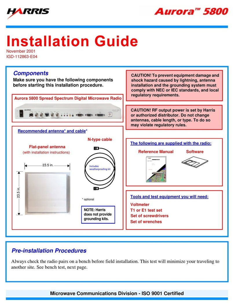
Harris
Harris Aurora 5800 User manual

Harris
Harris M5300 User guide

Harris
Harris Constellation Maintenance and service guide
Harris
Harris RF-7800W-OU49 series User manual

Harris
Harris M7300 Series Instruction Manual
Harris
Harris FlexStar User manual
