Harrison Mixbus VBM User manual

MANUAL VERSION: 1.5
DATE: 2 December 2021
NOTES: For VBM 1.2 release

MIXBUS VBM 2 December 2021
TABLE OF CONTENTS
1.0 INTRODUCTION.....................................................................................................................................6
1.1 PREMISE....................................................................................................................................................6
2.0 OVERVIEW...............................................................................................................................................7
2.1 INPUT SECTION..........................................................................................................................................7
2.2 VBM CHANNEL STRIP...............................................................................................................................9
2.2.1 Name Plate....................................................................................................................................12
2.2.2 Channel Redirect Section..............................................................................................................14
2.2.3 VBM Channel Strip - Signal Processing.......................................................................................19
2.2.4 Program B s Assign B ttons.........................................................................................................22
2.2.5 Lobby Assign B ttons....................................................................................................................25
2.2.5.1 Contributor O eration................................................................................................................26
2.2.6 Pan/Balance Control.....................................................................................................................27
2.2.7 Channel Slate................................................................................................................................27
2.2.8 M te and Solo B ttons..................................................................................................................27
2.2.9 Level Displays...............................................................................................................................27
2.2.10 Fader.............................................................................................................................................27
2.2.11 Meter.............................................................................................................................................28
2.2.12 Metering Point Select B tton........................................................................................................28
2.2.13 Gro p Assign B tton.....................................................................................................................29
2.2.14 VCA Assign B tton........................................................................................................................30
2.3 VCA MASTERS.......................................................................................................................................32
2.4 BUSES.....................................................................................................................................................35
2.4.1 Program B ses..............................................................................................................................37
2.4.1.1 Program Bus Name late............................................................................................................39
2.4.1.2 Redirect Section.........................................................................................................................40
2.4.1.3 Program Bus Signal Processing.................................................................................................40
2.4.1.4 Lower Section............................................................................................................................41
2.4.1.5 Sends Section.............................................................................................................................41
2.4.2 MixMin s B ses............................................................................................................................46
2.4.2.1 Sends Section.............................................................................................................................48
2.4.2.2 Show Sends Button....................................................................................................................48
2.4.2.3 Redirect Section.........................................................................................................................49
2.4.2.4 Program Level Slider.................................................................................................................49
2.4.2.5 Signal Processing Section..........................................................................................................49
2.4.2.6 Lower Section............................................................................................................................49
2.5 MONITOR STRIP.......................................................................................................................................50
3.0 ROUTING TOOL....................................................................................................................................55
4.0 SUMMARY..............................................................................................................................................59
5.0 REFERENCES........................................................................................................................................60
6.0 APPENDIX 1: ACE IFB PLUGIN.........................................................................................................61
6.1 DESCRIPTION...........................................................................................................................................61
6.2 USE.........................................................................................................................................................61
2

MIXBUS VBM 2 December 2021
7.0 APPENDIX 2: INSTALLATION AND LICENSING..........................................................................65
7.1 GETTING STARTED...................................................................................................................................65
7.1.1 Installing The Software.................................................................................................................65
7.1.2 Checking Licensing Stat s.............................................................................................................66
3

MIXBUS VBM 2 December 2021
LIST OF FIGURES
FIGURE 1: VBM CONTROL PANEL......................................................................................................................6
FIGURE 2: VBM INPUT SECTION.........................................................................................................................8
FIGURE 3: VBM STEREO CHANNEL STRIP......................................................................................................10
FIGURE 4: VBM MONO CHANNEL STRIP.........................................................................................................11
FIGURE 5: CHANNEL NAME PLATE FUNCTIONS..........................................................................................12
FIGURE 6: CHANNEL COMMENT BOX.............................................................................................................12
FIGURE 7: PLUGIN PIN CONFIGURATION WINDOW....................................................................................13
FIGURE 8: CHANNEL REDIRECT SECTION.....................................................................................................15
FIGURE 9: OPENING THE PLUGIN SELECTOR................................................................................................16
FIGURE 10: PLUGIN SELECTOR.........................................................................................................................17
FIGURE 11: CHANNEL EXTERNAL SEND........................................................................................................18
FIGURE 12: SIGNAL PROCESSING ACCESS.....................................................................................................20
FIGURE 13: CHANNEL STRIP PROCESSING.....................................................................................................22
FIGURE 14: PROGRAM BUS ASSIGN BUTTONS..............................................................................................23
FIGURE 15: PROGRAM BUS BUTTONS WITH FADER OPEN.......................................................................24
FIGURE 16: LOBBY-PROGRAM ACTIVENESS WITH FADER DOWN..........................................................25
FIGURE 17: LOBBY-PROGRAM ACTIVENESS WITH FADER UP.................................................................26
FIGURE 18: METERING POINT SELECTOR......................................................................................................28
FIGURE 19: CUSTOM METERING POINT..........................................................................................................29
FIGURE 20: GROUPING........................................................................................................................................29
FIGURE 21: CONTROL GROUPING OPTIONS...................................................................................................30
FIGURE 22: VCAS...................................................................................................................................................31
FIGURE 23: CHANNEL ASSIGNMENT TO VCA MASTER..............................................................................32
FIGURE 24: VCA MASTER...................................................................................................................................33
FIGURE 25: VCA MASTER NAME PLATE.........................................................................................................34
FIGURE 26: MASTER MUTE FROM VCA MASTER.........................................................................................35
FIGURE 27: VBM BUS MASTERS........................................................................................................................36
FIGURE 28: PROGRAM BUS MASTER...............................................................................................................38
FIGURE 29: PROGRAM BUS NAMEPLATE.......................................................................................................39
FIGURE 30: BUS SIGNAL PROCESSING............................................................................................................40
FIGURE 31: PROGRAM BUS MASTER SHOWING SENDS SECTION............................................................42
FIGURE 32: PROGRAM BUS SENDS SECTION.................................................................................................43
FIGURE 33: CHANNEL SENDS CONTROLS......................................................................................................44
FIGURE 34: BUS PANS LINKED..........................................................................................................................44
FIGURE 35: BUS PANS UNLINKED....................................................................................................................45
FIGURE 36: MIX MINUS BUS MASTER.............................................................................................................47
FIGURE 37: MIX MINUS BUS SHOW SENDS MODE.......................................................................................48
FIGURE 38: VBM MONITOR STRIP....................................................................................................................51
FIGURE 39: MONITOR SELECTOR.....................................................................................................................53
FIGURE 40: MONITOR STRIP IN SOLO..............................................................................................................54
FIGURE 41: ROUTING TOOL ACCESS...............................................................................................................55
FIGURE 42: ROUTING TOOL...............................................................................................................................56
FIGURE 43: SHOWING A PROGRAM BUS TO PROGRAM BUS CONNECTION..........................................57
FIGURE 44: MONITOR STRIP CONNECTION TO EXTERNAL INTERFACE................................................58
FIGURE 45: ACE IFB PLUGIN CONTROL PANEL............................................................................................62
FIGURE 46: ACE IFB PIN CONNECTIONS WINDOW.......................................................................................62
4

MIXBUS VBM 2 December 2021
FIGURE 47: ACE IFB - ADD SIDECHAIN INPUT..............................................................................................63
FIGURE 48: ACE IFB SIDECHAIN INPUT CONNECTION...............................................................................64
FIGURE 49: ACCESSING VERSION AND LICENSING INFORMATION........................................................66
FIGURE 50: ABOUT WINDOW.............................................................................................................................67
5

MIXBUS VBM 2 December 2021
Harrison Mixbus Virtual Broa cast Mixer (VBM)
1.0 Intro uction
Harrison Mixbus VBM is a clou -rea y virtual broa cast mixer. Base on Harrison Consoles
eca es-long experience pro ucing analogue an igital mixing consoles, VBM uses software
mixing technology evelope for Harrison's Mixbus DAW platform.
Figure 1 : VBM CONTROL PANEL
Mixbus VBM runs on MAC, Linux an Win ows platforms.
1.1 Premise
Mixbus VBM is a computer base igital mixer for live broa cast mixing applications. It is
tailore to applications that require multiple mix minus fee s an can provi e multiple program
outputs. It can be run locally or on a remote virtual server. Au io inputs an outputs to VBM are
over network connections an are not necessarily local to the broa cast engineer's physical
location.
6

MIXBUS VBM 2 December 2021
2.0 Overview
Figure 1 shows the VBM control panel. In the figure left to right, there are 6 basic sections to
the panel.
1. Input an Bus List
2. Input Section
3. VCA Masters
4. Mix Minus Buses
5. Program Buses
6. Monitor Section
The Input an Bus List is selectable an can be hi en if not nee e . A itionally, VCA
masters will not be isplaye if none have been create .
2.1 Input Section
Figure 2 shows the input section of Mixbus VBM. The input section is comprise of several
channel strips, the number of which is limite only by the amount of your computing power.
Channel strips are a e by creating Inputs or Contributors.
Channel strips may be either mono or stereo. The ones shown in Figure 2 happen to be
stereo.
At the top of the input section are 4 buttons. They are:
1. Template – This button is use when starting VBM for a new project. It provi es a fast
metho of configuring a full mixing session base on a preset list of channels an
names. The user can either accept the efaults or mo ify them as nee e . Once rea y,
pressing the OK button will create the selecte channels in the mixer in one step.
2. A Contributor –
DEFINITION: A "Contributor" is an au io source that has a MixMinus bus correspon ing
to its input channel.
This button a s both an input channel an a correspon ing MixMinus bus. The
contributor may be either stereo or mono.
3. A Input – This button a s an input channel. The input may be either stereo or
mono. No MixMinus bus correspon ing to this input is create .
4. A VCA – This button a s a VCA master. When a VCA master is create , all
channel strips have a VCA assign button a e at the bottom. See Section 2.2.14.
7

MIXBUS VBM 2 December 2021
Figure 2 : VBM INPUT SECTION
8

MIXBUS VBM 2 December 2021
2.2 VBM Channel Strip
Figure 3 shows a VBM channel strip. When a channel strip is create it can be chosen to be
either stereo or mono. The channel strip in Figure 3 is a stereo channel strip. The mono channel
strip is shown in Figure 4 an is i entical except for a pan control rather than a balance control
(see Section 2.2.6), an the level meter is a single meter rather than a pair of meters.
Features an functions of the channel strip are presente in the following sections.
9

MIXBUS VBM 2 December 2021
Figure 3 : VBM STEREO CHANNEL STRIP
10

MIXBUS VBM 2 December 2021
Figure 4 : VBM MONO CHANNEL STRIP
11

MIXBUS VBM 2 December 2021
2.2.1 Name Plate
The name plate has the name of the channel. Right OR left clicking on the name plate
provi es for renaming, changing colours an other controls.
Figure 5 : CHANNEL NAME PLATE FUNCTIONS
The "Comments" selection allows entry of notes or comments specific to this channel. Once
entere they may be rea at any time by accessing this selection again, as shown in Figure 6.
Figure 6 : CHANNEL COMMENT BOX
12

MIXBUS VBM 2 December 2021
"Pin Connections" brings up a win ow where the connections in an out of any plugins which
are present can be seen an mo ifie . An example of this win ow is shown in Figure 7 an
permits custom connections of the in an out ports to the plugins to be ma e, a ition an
connection of si echain inputs, MIDI Controls (where available) an so on. This option will not be
shown if the channel has no plugins inserte .
Figure 7 : PLUGIN PIN CONFIGURATION WINDOW
13

MIXBUS VBM 2 December 2021
"Protect Against Denormals" has to o with how computers process very small floating-point
numbers. In normal operation, this mo e shoul be turne off. If a 3r party plugin is causing
unusually high CPU loa , checking the box may re uce the loa .
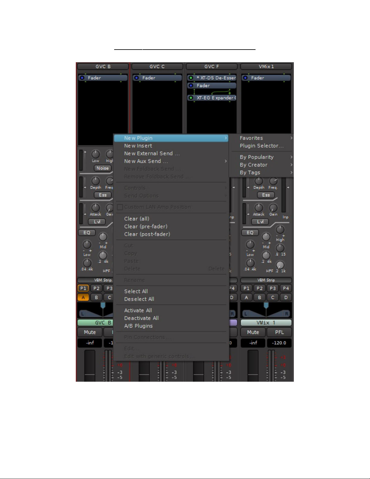
2.2.2 Channel Re irect Section
Right clicking in this area allows a ition of signal processing plugins, inserts an external
sen s, as shown in Figure 8.
Signal flow in the channel strip is as epicte , top to bottom, in the re irect area. The channel
main fa er is present by efault. The relative positions of the fa er, plugins an external sen s
may be rearrange simply by ragging the items up or own in the re irect area. For example, in
Figure 8 the XT-EG expan er plugin on channel GVC F may be place pre-fa er by ragging it
above the fa er (or ragging the fa er below it).
14
MIXBUS VBM 2 December 2021
Figure 8 : CHANNEL REDIRECT SECTION
Selecting the Plugin Selector allows insertion of a wi e variety of built-in an user-installe 3r
party plugin processors.
15

MIXBUS VBM 2 December 2021
Before the Plugin Selector opens, the user will be prompte to scan for thir -party plugins, as
shown in Figure 9.
Figure 9 : OPENING THE PLUGIN SELECTOR
Figure 10 shows the Plugin Selector. At the top is a list of the currently installe plugins.
Check boxes allow in ivi ual plugins to be flagge as favorites. Clicking on a plugin selects it an
lights up the "A " button. When presse , the plugin will be a e to the lower right box which
will hol the list of plugins to be inserte .
When there are large numbers of plugins installe it may be ifficult to fin the esire one.
The Plugin Selector provi es a Search facility with a number of filter options to ai in fin ing a
plugin. As seen in the figure, filters inclu e
filtering by type, for example effects, instruments or utilities
filtering by format, for example VST3, LV2, etc is provi e by selecting the pull own
filtering by creator, such as the Ar our Community, Harrison, etc by selecting the
pull own
The Search facility provi es for seaching a plugin by:
name
tags (which are shortcut IDs associate with every plugin)
Searching may ignore the filters by clicking on the "Ignore Filters when Searching" button.
16

MIXBUS VBM 2 December 2021
Figure 10 : PLUGIN SELECTOR
Selecting "New External Sen " will bring up the routing tool. Using this tool the channel signal
can be route anywhere, to a bus or to an external output. Figure 11 shows the routing tool. The
tabs on the right si e select general estinations such as buses, external har ware (or network
connections) an so on.
See Section 3 for more etails about the Routing tool an its use.
17

MIXBUS VBM 2 December 2021
Figure 11 : CHANNEL EXTERNAL SEND
18

MIXBUS VBM 2 December 2021
2.2.3 VBM Channel Strip - Signal Processing
Each channel strip has a comprehensive set of signal processing tools. These are:
3-ban EQ with highpass filter
leveler
e-esser
e-noiser
Single-clicking on the "VBM Strip" button above the program bus assign buttons opens the
signal processing tools on all channel strips an output buses. Signal processing on the channel
strip is shown in Figure 12. The signal processing parameters may be mo ifie by clicking an
ragging on the buttons an knobs irectly.
19

MIXBUS VBM 2 December 2021
Figure 12 : SIGNAL PROCESSING ACCESS
20
Table of contents
Popular Mixer manuals by other brands

Bosch
Bosch ErgoMixx MSM67140 operating instructions

CUISIMAT
CUISIMAT Dynamic FT 97 User and maintenance guide

Silverline
Silverline 264219 Original instructions

Makita
Makita DUT130 instruction manual

Galvin Specialised
Galvin Specialised CliniLever TM-BASCP manual

better chef
better chef IM-815WC Use and care book


