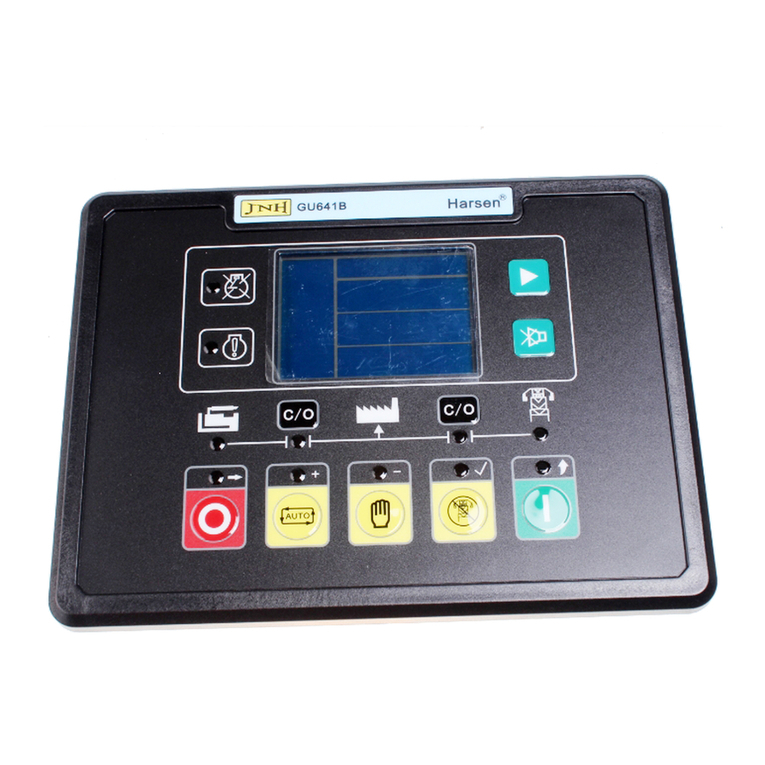
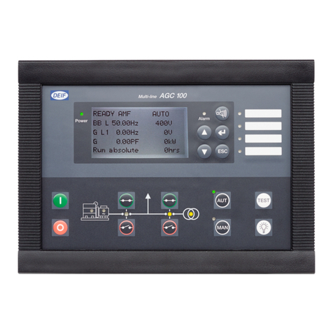
Harsen GU641A User manual

GU641AControllerOperation Manual
1
Theclarification ofnotation usedwithinthismanual:
WARNING:
AWARNINGindicatesapotentiallyhazardoussituation which,ifnotavoided,
couldresult indeath, seriouspersonalinjuryorpropertydamage.
CAUTION:
ACAUTIONindicatesapotentiallyhazardoussituation which,ifnotavoided,
couldresult indamagetoequipment orproperty.
NOTE:
ANOTEprovidesotherhelpfulinformation thatdoesnotfall underthe warning
orcaution categories.

GU641AControllerOperation Manual
2
WARNING:
Read thisentiremanualpertainingtotheworktobe performed before
installing,operating,orservicingthiscontroller.Practiceall plantandsafety
instructionsandprecautions.Failuretofollowinstructionscancausepersonal
injuryand/orpropertydamage.
Theengine orothertypeofprimemovershouldbeequipped withan over
speed shutdowndevicetoprotectagainstrunawayordamagetotheprime
moverwithpossiblepersonalinjury, loss oflife, orpropertydamage.
The overspeed shutdowndevicemustbetotallyindependentofthe prime
movercontrolsystem.Anovertemperatureorlowpressureshutdowndevice
mayalsobeneeded forsafety,asappropriate.
CAUTION BATTERYCHARGING
Topreventdamagetoacontrollerthatusesan alternatororbattery-charging
device,makesurethechargingdeviceisturnedoff beforedisconnectingthe
batteryfromthesystem.
Controllerscontainstatic-sensitiveparts.Observethe followingprecautionsto
prevent damagetotheseparts:
Donotdisassemblethe rearback ofcontrollerand touchthecomponentsor
conductorson aprinted circuit board.

GU641AControllerOperation Manual
3
Contents
1. Description..................................................................................................................4
2. TheOutlineDimensionDrawingsandControllerWiring........................................5
3. Panel Operation..........................................................................................................8
4. Control andOperationInstruction..........................................................................10
5. MeasureandDisplayData.......................................................................................18
6. Pre-alarm andShutdownAlarm...............................................................................19
7. ParametersSetting...................................................................................................23
8. InstallationGuide......................................................................................................42
9. LCD displaysandMenu System..............................................................................51
10. Technical Specification.............................................................................................54

GU641AControllerOperation Manual
4
1.Description
GU641Aisanewgeneration AutomaticMains(Utility)FailuremoduleforsingleGenset, whichadopts
bran-newoutline configuration,focuson the requirementsofcustomers,and perfectlyimprovesthe
performanceofcontroller.It fullymeetsthe autocontrolrequirementsofdifferentkindsofGensetfor
userorspecialassemblyfactory.
Themodulealsomonitorsand protectstheengine,indicatingoperationalstatus,faultconditionsand
meteringon the front panelLCD andLED.
lTrue RMSmeasureofvoltageand current.
l2analoginputsforkindsofoptionalbuilt-insensors, parametersalsocan beconfigured byuser.
lMoreoutputsofconfigurableauxiliarycontrolrelays.
lMoreconfigurableisolated digitalinputs.
lButtonsoncontrolpanelareusedforselectingcontrolmodes,startingandstoppingthe operating
procedure,displayingdataandmodifyingthe parameters.LEDindicatorsareusedforindicating
the operation mode ofcontrollerandtherunning statusofGenset, and LCD displayseach
measuringparameterand status.
lFlexibleequipped withRS485,RS232andUSB,realizingremotemonitor;orcommunicated with
PC,fullyrealizingfunctionsof remotesignaling,telemeteringand remotecontrol,can read and set
the runningparametersofcontroller.
lAll connectionsofthecontrollerarebysecureplugandsocket,foreaseandconveniencetoconnect,
move, maintainandreplacethedevice.
ThismanualisonlysuitableforGU641AAutomaticcontrolmodule,usermustcarefullyread
thismanual first.

GU641AControllerOperation Manual
5
2.TheOutlineDimensionDrawingsandControllerWiring
2.1Following Details:
ModuleDimensions W192mm H144mm
PanelCutout W174mm H126mm
Thickness D56mm (without connection)

GU641AControllerOperation Manual
6
2.2Terminal Connections:
Pin
no.
Function Description Signal Dim
1 GEN. VL1-N input 0-346Vac 1mm²
2 GEN. VL2-N input 0-346Vac 1mm²
3 GEN. VL3-N input 0-346Vac 1mm²
4 GEN. Neutral 1mm²
5 Not used
6 MAINSVL1-N input 0-346Vac 1mm²
7 MAINSVL2-N input 0-346Vac 1mm²
8 MAINSVL3-N input 0-346Vac 1mm²
9 MAINSNeutral 1mm²
10 I1Gen current input (S1) 0-5A 2.5mm²
11 I2Gen current input (S1) 0-5A 2.5mm²
12 I3Gen current input (S1) 0-5A 2.5mm²
13 Common portforcurrent inputs(S2) 0-5A 2.5mm²
14 LOPsensor <1KΩ2.5mm²
15 HETsensor <1KΩ2.5mm²
16 Common portforsensor 2.5mm²
17 Common portforrelayoutputs 2.5mm²
18 Fuelsolenoidrelayoutput N.O. contact, 16A/30Vdc 2.5mm²
19 Start (Crank)relayoutput N.O. contact, 16A/30Vdc 2.5mm²
20 Relayoutput 3(GCBclose/open) N.O. contact, 3A/30Vdc, configurable(1) 1mm²
21 Relayoutput 4(MCBclose/open) N.O. contact, 3A/30Vdc, configurable(2) 1mm²
22 Relayoutput 5 N.O. contact, 3A/30Vdc, configurable(3) 1mm²
23 Relayoutput 6 N.O. contact, 3A/30Vdc, configurable(4) 1mm²
24 chargerexcitation poweroutput ifnot used, donot connect tonegative 1mm²
25 Configurabledigitalinput signal1 lowlevelisactive 1mm²
26 Configurabledigitalinput signal2 lowlevelisactive 1mm²
27 Configurabledigitalinput signal3 lowlevelisactive 1mm²
28 Configurabledigitalinput signal4 lowlevelisactive 1mm²
29 Configurabledigitalinput signal5 lowlevelisactive 1mm²
30 Magneticpick-upsignal(+) 1-70Vac 2cores
shielded
31 Common forconfigurableinputsand
magneticpick-upsignal(-)
32 Batterysupply(+B) 2.5mm²
33 Batterysupply{-B} 12V/24V(8-35Vdccontinuous) 2.5mm²
34 Ground 2.5mm²
NOTE:
lRelayoutput3and 4arerespectivelyconfigured asGCBand MCB
close/open relaywhen defaultsetting,howeverbothcan bereconfigured
byuserifrequired.

GU641AControllerOperation Manual
7
2.3Typical Wiring Diagram
Afusewiththe ratingof1Ashall beprovided externaltotheequipment.

GU641AControllerOperation Manual
8
3.Panel Operation
Theoperationpanelconsistsof3sections:LCD displayindicatingmeasurementparameters,LED
indicatorforcommon failure, and pushbuttonsforGenset and selection ofcontrolmodes.
LCD can display3-rowdatainthe sametime.LCD alsohasabacklightsothatthe operatorcan clearly
read information dayornight. Afterpressing anybutton thebacklightwillautomaticallyturnoffaftera
preset time.
TheLCD displayanditscontrolpushbuttonsprovide afriendlyoperationalinterfacefortheoperatorto
easilycontrolthe Genset, read information and parametersetting.
3.1Control buttonsand LED
Function Description Tag
Scroll Button
Scroll menu forparametersdisplay/enterintoorexitparameterssettingby
pressingand holdingthisbuttonfor2sec.
MUTE/ LampTestButton
When failureoccurs,alarmbuzzersounds.Pressingmutebuttonwillmutethe
sound.LCD displaysmuteicon.Press itagainwillclean mutefunction,buzzer
continuestosound.Press andholdthisbutton for2sec,allLEDsilluminate
simultaneously.
AUTO ModeButton/ LED/ “+”ValueIncrease
Thepushbuttonisusedforselecting “automode”.When the controllerisrunning
inAUTOmode,the LEDabovethe button isilluminated.Theactivation and
deactivation ofthe “remotestartsignalinput”and “MainsFailure”controlsthe
startingand stoppingofthe Genset.
When inparameterssettingmode,thisbuttonisused toincreasevalue /scroll
downmenu.
MANModeButton / LED/ “-”ValueDecrease
The pushbutton isusedforselecting “manualmode”.When the controlleris
runninginMANUALmode,the LEDabovethe pushbutton isilluminated.TheStart
and Stoppushbuttonscontrolthe startingofthe Genset.
When inparameterssettingmode,thisbutton isused todecreasevalue /scroll up
menu.
TESTModeButton/ LED/ “”ConfirmParametersConfigure
The pushbutton isused forselecting “testmode”.When controllerisrunningin
TESTmode,the LEDabovethepushbuttonisilluminated, thecontrollerstartsthe
generatorsimulatingMainsfailureand theactivation of “remotestart signal”.
When inparameterssettingmode,thisbuttonisused toenterintosubmenu /
confirmmodification.
STARTButton / LED/ Return
The pushbutton isusedformanuallystartthe Genset. When controllerisrunning
inMANUALmode, press thisbutton tostart the generator.
When inparameterssettingmode, thisbutton isusedtoreturn.

GU641AControllerOperation Manual
9
STOP/ RESETButton/ “→”MoveSetting
ThePushbuttonisusedformanuallystopstheGenset. Nomatterwhatmode the
controllerisrunning,pressand holdthisbutton for2sectostopthe generator,the
mode ofthe controllerwillbedefaultto “MAN”mode automaticallyfrom “AUTO”or
“TEST”mode andthegeneratorwill beshutdownaftercooldownperiod,during
the cooldownperiod ifyoupress andholdthisbuttonfor2secagain, thegenerator
will beshut downimmediately.
Iffailureoccurs, press thisbutton, the shutdownalarmlockout can becleared.
When inparameterssetting mode,thisbutton isused tomovetonextparameters
C/O Button
Thereare2C/O buttonsrespectivelybeside the Mainsand Gen icons.Theyare
used toclose/open the switchesofMainsand Genwhen controllerisrunningin
MANUALmode.
ShutdownAlarm(FAILURE)LED
TheLEDwillilluminatepermanentlywhen shutdownalarmoccurs.
Pre-alarm(WARNING)LED
TheLEDwillilluminatepermanentlywhen pre-alarmoccurs.
GEN. Normal LED
Gen.normalLEDwill illuminateafterbothvoltageand frequencyof the Gen.reach
loadingvoltageand frequency.
GCB/MCB ClosedLED
LEDwillilluminatewhen GCB/MCBisclosed andpowersupplied byGen/Mains,
LEDwill flashwhen GCB/ MCBfailureoccurs.
MAINSNormal LED
MainsnormalLEDwillilluminateafterbothvoltage and frequencyofthe Mains
reachthepreset value range.

GU641AControllerOperation Manual
10
4.Control andOperationInstruction
The controllerhas3modes: AUTO, MANUALand TEST.
4.1Operation Modes Setting:
Operation Description
Press andholdthe “AUTO”buttonfor2sec,theLEDabovethebutton
isilluminated; the controllerisrunningin “AUTO”mode.
Press andholdthe “MAN”button for2sec,theLEDabovethebutton
isilluminated; the controllerisrunningin “MAN”mode.
Press andholdthe “TEST”button for2sec, theLEDabovethe button
isilluminated; the controllerisrunningin “TEST”mode.
NOTE: Only1mode canbeselectedfromabove3modes.
4.2AUTO Control Sequence:
Thecontrollerisrunningin “AUTO”mode.
WhenMains(Utility)isnormal, Mainsison load:
When Mainsisnormal,bothvoltageand frequencyofMainsarewithinthe rangeofpresetvalue,the
MainsNormalLEDilluminates,the timerfor MainsONdelay isactivated,when ittimesout, the MCB
close/open relaycloses,thetransferswitchswitcheson Mains,theMainsAux.Switch’scontactfeeds
back the signaltoaconfigurableinput on ourcontroller. The MCBclosed LEDilluminates.
WARNING:
lTheMainsNormalLEDilluminated meansthatbothvoltageand
frequencyofMainsarewithinthe rangeofpresetvalues;MainsNormal
LEDflashingmeanseithervoltageorfrequencyofMainsareoverthe
rangeofpresetvalues;MainsNormalLEDdoesnotilluminatemeansthat
the Mainsvoltageislowerthan themeasuringrange.
lDonotassumethe MainsisnotavailableifMainsNormalLEDdoesnot
illuminate.
Mainsfail toload:
IfMCBclose/open relayisclosed,thetimerforMCBclosingisactivated,when ittimesout, ifthe
controllerdoesnotreceivethe feed back signalfromthe MainsAux.Switch’scontact, then Mainsfail to
load isactivated.
NOTE:
lAbovecontrolprocedure,assumesthatone ofconfigurableinputshas
been configured as MainsAux.SwitchClosed andconnectstheswitch’s
N.O. Aux.contacttothisport. Ifyoudo notconfigurean inputas Mains
Aux.SwitchClosed,then theMCBclosed LEDilluminatesisonlyan
indication thattheMCBclose/openrelayshouldhavebeen closed,under
thiscondition,thealarmfor Mainsfail toload isinactive,andthealong
function ofstart Genset isalsoinactive.

GU641AControllerOperation Manual
11
GeneratorAutoStartSequence:
Controllerimplementsfollowingprocedurewhen Mainsvoltagefailureoccurs(itmeansthatthe
controllerdetectingeitherthevoltageorthefrequencyofMainsisovertherangeofpresetvaluesand
delayconfirmed), orMainsfailtoload,orremotestart signalisactiveand Mainsfailure;
NOTE:
lToachieveremotestart,oneofconfigurableinputsmustbedefined as
remotestart signal.
TheStartdelaytimerisactivated,when ittimesout, thePreheatrelayoutputisenergised (ifpreheat
function selected),thetimerstarts.When ittimesout, the fuelrelayoutputisenergised,andoperates
the fuelsolenoidoftheengine.After300msdelay,the startrelayoutputisenergised,thestartmotor
engagesandbeginstocrank.When theengine speed reachesthecrankcutoutRPM,the startrelay
outputisde-energised and the safety-on delaystarts.When the safety-on timesout, ifthe controller
detectsthattheparametersofthe Gensetsuchasvoltage, frequency,oil pressure, coolant temperature
arenormal,and nootherfailureisdetectedthisindicatesthe Gensethassuccessfullystarted and
runningnormally. The LCD displaystheGenset Measurement Parameters.
When Generatorisrunningnormally,Gen.NormalLEDilluminates,the timerforGEN.ONdelayis
activated,when ittimesout,GCBclose/openrelaycloses,the transferswitchswitcheson Gen.The
Gen Aux.Switch’scontactfeedsback asignaltoaconfigurableinputon thecontroller.GCBclosed
LEDilluminates.
NOTE:
lIfMainsfailstoload,the startsequenceisinitiated withoutthe start-delay
timer.
lWhen Mainsvoltagefailureand remotesignalisactive,the start-delay
timerisactivated,ifremotestartsignalisinactiveorMainsvoltage
resumestonormalduringthisperiod,thestartdelaytimerterminates
immediately,thecontrollerterminatesthestartingprocedure,andthen
recoverstothe originalstandbystatus.
lDuringcrankingoridleperiod, ifthe remotestart signalisinactiveorMains
voltageresumestonormal,the controllerstopsthestartprocedure,then
recoverstothe originalstandbystatus.
lUnderanyconditions,GEN.ONdelayonlycan bestarted afterSafety-on
Delaytimesout.
NOTE:
lThestartmotorwill poweroffwhilecrankingifthereareoneofthe
followingconditionsoccur:
A.The ACgenerator’sfrequencyreachesthepresetvalue (configurable
crankingcutout value);
B. The ACEngine speedreaches crankcutoutvalue;
C. Generator’svoltagereachesthe crankcutoutvalue (optional);
D. Chargervoltagereaches crankcutoutvalue (optional);
E. CutoutP-delaytime’sup(optional);
F. Crankingtime’sup.
lControllercan notimplementcrankprocedureinoneoffollowing
conditions:
A.The ACgenerator’sfrequencyreachesthepresetvalue (configurable
crankingcutout value);
B. The ACEngine speedreaches crankcutoutvalue;
C. Generator’svoltagereachesthe crankcutoutvalue (optional);
D. LOPswitchisopened oroil pressureishigherthan crankcutoutvalue
(optional).

GU641AControllerOperation Manual
12
CAUTION:
Ifmagneticpickupisnotused,toavoiddamagetothe startmotorpleasemake
surethe generator’svoltage ishigherthan themeasurablevalue of controllerwhile
cranking,sincethecrankcutoutsignalissensedfromthe generatorvoltageand
frequency.
NOTE:
Abovecontrolprocedure,assumesthatone ofconfigurableinputshasbeen
configured as GenAux.SwitchClosed and connectsthe switch’sN.O. Aux.
contactsignaltothisport. If you do notconfigurean inputas GenAux.Switch
Closed,then the GCBclosed LEDilluminatesisonlyan indicationthatthe
GCBclose/open relayshouldhavebeen closed.
Ifyou haveselected idlefunction,the idlerelaywillbeclosed atthe sametimeasthe crankrelayis
closed,the idletimerwillbegincountingdownaftersuccessfulcrank,when ittimesout, the idlerelay
opens, otherprocedureisthe sameasabove.
NOTE:
Controllerwill notdetectundervoltage,underfrequency, underspeed,andcharge
failureduringidleperiod.
RepeatCrank: Duringthe crankperiod,ifthe enginecan notignitecontrollerwillnotoutputstartsignal
duringcrankrest. Oncecrankrest timertimesoutthestart relayenergisesonceagainand willattemptto
startengineagain.The aboveprocedurewill berepeated until engine successfullyignitesorreaches
the preset numberofcrankattempt.
If anyshutdownalarmoccursduringcrank, controllerwill stopcrankingimmediately,andthe Genset onlycanbe
restartedafterclearingthefailureand reset.
StartFailure: When theprocedureaboverepeatsagainandagainandreachesthepresetnumberof
crankattempt, the crankrelayoutputisthende-engised.ThefailureLEDilluminatesandtheLCD
displays Fail toStart.
CAUTION:
If Fail toStartoccurs,operatormustcheck the wholeGensetsystemtofind out
failurereason,onlyafterclearingthe failurecan press “STOP/RESET”button
torelievefault lock out status,andrestart theGenset.
Mainsreturnand generatorshutdownsequence:
WhenMainsresumestonormal,MainsNormalLEDilluminates,the MainsONdelay timerisactivated,
GCBclose/open relayisde-energised afterittimesout,MCBClose/openrelayisenergised,transfer
switchswitcheson Mains,the MainsAux.Switch’scontactfeedsback the signaltoaconfigurableinput
on ourcontroller,MCBclosedLEDilluminates.
At the sametimeasthe MCBclose/openrelayisenergised, thetimerforcooldownisactivated,whenit
timesout, thefuelrelayde-energises,generatorstopsand recoverstoitsstandbystatus.
NOTE:
Ifyou donotconfigurean inputas MainsAux.SwitchClosed,then the MCB
closed LEDilluminatesbutisonlyanindicationthattheMCBclose/openrelay
shouldhavebeen closed.

GU641AControllerOperation Manual
13
Stop Failure: When cooldowntimesout,thefuelrelayopensandthetimerforStopdelaybegins. Ifthe
controllerdetectsthatthe voltageofthe generatororoil pressureorthe speed ofengine isgreaterthan
the cutoutvaluesorLOPswitchisopen,when ittimesout,the failureLEDilluminatesand theLCD
displays Fail tostop.
NOTE:
Afterstopfailure,the controllerwillnotenergisethe crankrelayoutputifthe
failurehasnot been removed and thecontrollerreset.
Generatorautostartconditions:
Whenthe controllerisin “AUTO”mode,itwill autostart underthefollowing3conditions:
lMailsvoltagefailure
lRemotestartsignalisactive
lMCBfailure
Ifyou do notdefine oneoftheconfigurableinputsasRemoteStartSignal,whenthe Mainsfails,the
controllerwillautomaticallyinitiatethe startsequence.
Ifone oftheconfigurableinputshasbeen defined asRemoteStartSignal,whenremotestartsignalis
activeand Mainsfails,the controllerwill initiatestartsequence.HoweverifthereisaMainsfailurebut
remotestart inputisnot activethe controllerwillnotinitiatestart sequence,but the Mainsclose/open relay
willopen.
IfGensethasstartedsince Mainsfailtoload,when failureisremoved andcontrollerunlocked by
pressingresetbutton,GCBclose/open relayopens,MCBclose/open relaycloses,transferswitch
switchestheloadtoMains.
NOTE:
Ifno configurableinputwasdefined as MainAux.Switchclosed, the alarmfor
Mainsfail toload isinactive.
4.3MANcontrol Sequence:
Thecontrollerisrunningin “MANUAL”mode.
Mainsisnormal, Mainsison load:
When MainsisnormalmeansthatbothvoltageandfrequencyofMainsarewithinthe rangeofpreset
value, the MainsNormalLEDilluminates, the MCBclose/openrelaywillnotcloseautomatically.
Press the “C/O”button ofMainstoclosethe Mainsswitchmanually,then Mainsison load, the MainsAux.
Switch’scontactfeedsback thesignaltoaconfigurableinputon ourcontroller,MCBclosedLED
illuminates.Press the “C/O”button ofMainsagaintoopen the Mainsswitchmanually,the Mainsisoff
load,the MCBclosed LEDisturnedoffat thesametime.
Ifyou pressthe “C/O”buttonofMainswhen Genisonload,the GCBclose/openrelaywillbeopened first,
then Genisoffload,the MCBclose/open relaycloseslater,Mainsisonload.
NOTE:
When the controllerisrunningin “MANUAL”mode,Mainsmustbenormal,orthe
“C/O”button ofMainswill bedisabled.

GU641AControllerOperation Manual
14
Generatorstarting sequence:
Pressing “START”button the fuelrelayenergises,and operatesthe fuelsolenoidofengine,After
300msdelay,thestartrelayoutputisenergised,thestartmotorengagesandbeginstocrank,when the
engine speed reachesthecrankcutoutRPM,thestartrelayoutputisde-energised and the safety-on
delaystarts.When the safety-on timesout, ifthe controllerdetectsthattheparametersofthe Genset
suchasvoltage,frequency,oil pressure,coolanttemperaturearenormal,and nootherfailureis
detectedthisindicatestheGensethassuccessfullystarted andrunningnormally.TheLCD displaysthe
Genset Measurement Parameters.
Afterbothvoltageand frequencyofgeneratorrespectivelyreached the loadingvalue,the Gen.Normal
LEDilluminates, the GCBclose/open relaywillnot beclosed automatically.
Pressthe “C/O”buttonofGentoclosetheGenswitchmanually,Genisonload,theGen Aux.Switch’s
contactfeedsback the signaltoaconfigurableinputon ourcontroller,GCBclosedLEDilluminates.
Pressthe “C/O”buttonofGen againtoopentheGenswitchmanually,Genisoffload,theGCBclosed
LEDisturnedoffat thesametime.
Ifyou pressthe “C/O”button ofGen when Mainsisonload, the MCBclose/openrelaywillbe openedfirst,
then Mainsisoff load, the GCBclose/open relaycloseslater, Genisonload.
NOTE:
lWhen the controllerisrunningin “MANUAL”mode,the Gen mustbe
normal, orthe “C/O”button ofGen will bedisabled.
lGCBand MCBclose/open relaysareelectricallyinterlocked,theycan’tbe
closed at the sametime.
Generatorstopping sequence:
Press “STOP”button,GCBclose/open relayopens,the generatoriswithoutload,the cooldowntimer
starts,whenittimesout,the fuelrelayisde-energised,then thefuelsolenoidopensimmediately,
generatorstopsand goestostandbystatus.
Ifpress “STOP”button againduringcooldownperiod,generatorstopsimmediatelywithoutcooldown
time.
4.4TESTControl Sequence:
WhentheControllerisrunningin “TEST”modemeansitsimulatesMainsfailureautomatically.Thereare
twokindsof “TEST”modes,one is “Testwithload”,anotheris “Testwithoutload”,and theycan be
selectedthroughparametersetting.
Testwithload: GCBclose/openrelaywillbe closed afterthe generatorisstartedsuccessfullyand
runningnormally, thenGenwillbeonload.
Testwithoutload: GCBclose/open relaywillnot beclosed afterthe generatorisstartedsuccessfullyand
runningnormally, theMainsremainonload.
4.5Thestartand stop Sequence ofenginewhose fuel solenoidisN. O.type:
Therearetwokindsoffuelsolenoidsforanengine,one isN.C.type,thevalveofthissolenoidisclosed
whenthe engineisinstandbyanditcan beopenedbyswitchingon power;anotherisN.O.type,the
valveofthissolenoidisopenedwhenengineisinstandbyand itcan be closedbyswitchingonpower.All
controlsequencesaboveareforN.C. type.
Startcontrol sequence forN.O. type:
Duringthestartingsequencethe fuelrelayofcontrollerwill notenergise,fuelsolenoidisoff power,fuel
solenoidisnormallyopen sonosignalrequired forfuelsolenoidtoactivate.

GU641AControllerOperation Manual
15
Stop control sequence forN.O. type:
Duringthe controller’sstopsequence, the fuelrelayenergises,fuelsolenoidison power, the fuelsolenoid
closesthefuelvalveandtheengine beginstostop.Afteradelay(sameasStopdelay)fuelrelayde-
energises,disconnectingthesupplyfromthe fuelsolenoid.
Othercontrol sequences aresameas enginewhose fuel solenoidisN. C. type.
4.6Idlefunction:
For idle function configureone ofthe configurableoutputsas idle.
Refertothe flowchart 4.9 forstart andstopfor idle controlflows.
NOTE:
Controllerwill notdetectundervoltage,underfrequency, underspeed,andcharge
failureduringidleperiod.
4.7Preheatfunction:
For Preheat function,configureoneoftheconfigurableoutputsas Preheat,The controllerhas4
selectablepreheatcontrolmodesasbelow:
Mode 1 —duringpreheat time, preheat relayoutputenergises.
Mode 2 —duringpreheat time,preheat relayoutput energisesuntil the successfulignition.
Mode 3 —duringpreheat time,preheat relayoutput energisesuntil safety-on delaytimesout.
Mode 4 —oneofthe configurableinputsisdefinedas Preheat,preheatrelayoutputenergiseswhen this
configurableinputisactive, andde-energiseswhen configurableinput isinactive.
Forpreheatmode 1to3, pleaserefertothe flowchart 4. 9 forstart andstopfor Preheat controlflows.
Forpreheat mode 4, preheat function isactiveimmediatelywhen the controllerisswitched on power.
Duringcrankperiod, the Preheat relayoutputwill notenergiseinanyofabovemodes.
LCD displaysicon ofpreheat operatingstatuswhen preheat relayoutputenergises:

GU641AControllerOperation Manual
16
4.8Thefunctionofforcingstart
Reason toadd thisfunction tothecontrolleristhat when theengine underabnormalconditions, e.g. the
batteryvoltageistooloworambienttemperatureistoo low,orgeneratoronlyoutputsvoltageat ahigh
speed when magneticpick-upisnotused,theGensetcannotbestarted successfullywhen it
implementsthe build-upcrankingprocess ofcontroller.Thereare2methodstosolvetheseconditions
inthe controller:
Firstmethod: when controllerisrunningin “MANUAL”mode, normallythe cranktimewillnot exceedthe
pre-setvalue, but you can press “START”buttonandholdwithout changingthe related parametersuntil
ithasstarted,the cranktimedependson the holding timeon thebutton. Safety-on timerbeginsafterit
hassuccessfullystarted.The otherprocessesandprotectionsarethe sameasforanormalstart.
Second method:when controllerisrunningin “MANUAL”mode,configurethe “EX.Crankpermit”as
“1”,shownasschematicbelow,aPB switchisexternallymounted tocontrolcranking.ClosePB switch,
engine cranks,when the speed reaches150RPMorgeneratorvoltageoutputisnotless than AC20Vif
magneticpick-upisnotused,thencontrollerfunctionsaretriggered,thefuelrelayoutputisenergised,
safety-on timerbeginsafterthe speedreachescrankcutoutvalue,theotherprocessesandprotections
arethe sameasnormalstart. Ifthe speed fallsbelow150RPMwithinsafety-on time,controllerwill be
reset andreturntostandbystatus.
CAUTION:
lWenormallydon’trecommend usingthe second method tosolvethis
condition.
lPayattentiontotheinstallationofPBswitchtoavoidcrankingwhentheGenset is
running.

GU641AControllerOperation Manual
17
4.9Flowchartforstartand stop
T1 startdelay
T2 cranktime
T3 pre-heat time
T4 safety-on delay
T5 idletime
T6 Stopdelay
NOTE:
IfT4islongerthan T5, oil pressureprotection isignored duringT5.
IfT4isshorterthanT5,oil pressureprotection becomeseffectiveafterT4in
T5.

GU641AControllerOperation Manual
18
5.MeasureandDisplayData
Mains3phasesVPh-N L1-NL2-NL3-N
Mains3phasesVPh-Ph L1-L2L2-L3L3-L1
Mainsfrequency Hz(L1)
Gen 3phasesVPh-N L1-NL2-NL3-N
Gen 3phasesVPh-Ph L1-L2L2-L3L3-L1
Gen frequency Hz(L1)
Gen 3phasescurrent I1I2I3
Gen totalapparent power ∑A
Gen totalactivepower ∑P
Gen powerfactor PF(AV)
Engine speed RPM (signalderived frommagneticpick-uporgeneratorHz)
Engine oil pressure Bar (signalfromengine LOPsensor)
Engine coolanttemperature (signalfromengine HETsensor)
Batteryvoltage Vdc
Genset RunningHour Hour

GU641AControllerOperation Manual
19
6.Pre-alarm andShutdownAlarm
6.1Pre-alarm(warning)
(NOTE:Pre-alarmsarenon-criticalfailureconditionsand do notaffecttheoperation ofthe
generatorsystem, they servefordrawing theoperators’attention toanundesirablecondition so
they canremoveittoensurecontinuousrunning ofthesystem.WhenPre-alarmsoccur,the
Pre-alarmLEDilluminates,butfailurewill notbelockedoutand theunitwill notshutdown.
Once thePre-alarmfailureisremovedthePre-alarmLEDwill automaticallyturnoff.)
Pre-alarm / Description LCD displays
CHARGEFAILURE:Aftersafety-ontimesup,ifthechargingvoltagefromthe
excitation contactofalternatorislowerthanthe “ALT.lowpreALM”,the pre-
alarmLEDilluminatesand thebuzzersounds,LCD displays:
BATT.UNDERVOLT:Ifcontrollerdetectsthat batteryvoltagehasfallenbelow
the “Batt.Undervolt”,pre-alarmLEDilluminatesandthe buzzersounds,LCD
displays:
Forexample, “Batt. Undervolt”presetas:23.6V,when batteryvoltagefalls
belowthisvalue,LCD flashinglowvalue icon.
BATT.OVERVOLT:Ifcontrollerdetectsthatbatteryvoltagehasexceededthe
“Batt. overvolt”,the pre-alarmLEDilluminatesandthe buzzersounds,LCD
displays:
Forexample, “Batt. overvolt”presetas:28.2V,when batteryvoltageexceeds
thisvalue,LCD flashinghighvalueicon.
LOWOILPRESS:Ifcontrollerdetectsthattheengine oil pressurehasfallen
belowthe “Oil-PlowpreALM”afterthesafety-ontimerexpired, the pre-alarmLED
illuminatesandthebuzzersounds,LCD displays:
Forexample, “Oil-PlowpreALM”presetas:2.2BAR,when engineoilpressure
fallsbelowthisvalue,LCD flashinglowvalue icon.
HIGHTEMP:Ifcontrollerdetectsthatengine coolanttemperaturehasexceeded the
“CoolantpreALM”,the pre-alarmLEDilluminatesandthebuzzersounds,LCD
displays:
Forexample, “CoolantpreALM”presetas:95℃,when engine coolanttemperature
exceedsthisvalue, LCDflashinghighvalue icon.
OVERSPEED:Ifengine speedexceedsthe “OverSP preALM”,the pre-alarm
LEDilluminatesand thebuzzersounds,LCD displays:
Forexample, “OverSP preALM”presetas:1600RPM,when engine speed
exceedsthisvalue,LCD flashinghighvalue icon.
UNDERSPEED:Ifengine speed fallsbelowthe “UnderSPpreALM”afterthe
safety-ontimerhasexpired,thepre-alarmLEDilluminatesandthebuzzersounds,
LCD displays:
Forexample, “UnderSP preALM”presetas:1440RPM,when engine speed
fallsbelowthisvalue,LCD flashinglowvalue icon.
OVERCURRENT: configure “Overcurrentaction”as “warning”,if controllerdetectsthat
anyphaseoutputcurrentexceedsthe “Overcurrentlevel”afterthe safety-on timerhas
expired,thepre-alarmLEDilluminatesandthe buzzersounds,LCDflashinghigh
value icon.

GU641AControllerOperation Manual
20
GEN.OVERVOLT:Ifcontrollerdetectsthatanyphasevoltage ofgeneratorhas
exceededthe “GEN-VoverpreALM”afterthesafety-ontimerhasexpired,the pre-
alarmLEDilluminatesandthebuzzersounds, LCD displays
Forexample, “ratingvoltage”presetas:220V, “GEN-VoverpreALM”presetas:
115%,when the generatoroutputvoltageexceedsthisvalue,LCD flashinghigh
value iconforcorrespondingphase.
GEN.UNDERVOLT:If controllerdetectsthat anyphasevoltageof generatorhas
fallen belowthe “GEN-VunderpreALM”afterthesafety-ontimerhasexpired,the
pre-alarmLEDilluminatesand thebuzzersounds,LCDdisplays:
Forexample, “ratingvoltage”presetas:220V, “GEN-VunderpreALM”preset
as:90%,when thegeneratoroutputvoltage fallsbelowthisvalue,LCD flashing
lowvalue icon forcorrespondingphase.
OVERLOAD:If controllerdetectsthatthe activepowerofgeneratorhasexceeded the
“KWOverload preALM”afterthe safety-on timerhasexpired,thepre-alarmLED
illuminatesandthebuzzersounds,LCD displays:
Forexample, “ratingactivepower”presetas:300KW, “KWOverload preALM”
presetas:90%,when thegeneratoractivepowerexceedsthisvalue,LCD
flashingiconforcorrespondinghighvalue.
D-INPUT:IfoneofConfigurableD-inputshasbeenconfigured aspre-alarm, when
D-inputisactive,thepre-alarmLEDilluminatesandthebuzzersounds,LCD
flashingD-Input icon.
GCB FAILURE:If GCBclose/open relayisclosed,the timerforGCBclosingis
activated,when ittimesout,ifthecontrollerdoesnotreceivethefeedback
signalfromGen Aux.Switch’scontact, thenGenfail toloadalarmisactivated.
TheGCBclosedLEDflashesand thebuzzersounds.
MCB FAILURE:IfMCBclose/open relayisclosed,the timerforMCBclosingis
activated,when ittimesout,ifthecontrollerdoesnotreceivethefeedback
signalfromMainsAux.Switch’scontact, then Mainsfail toloadalarmis
activated. TheMCBclosed LEDflashesandthebuzzersounds.
NOTE:
lControllercontinuouslydetectsbatteryvoltageduringstandbyperiod and Battery
Under/OverVoltage Pre-alarmsareactive.
lBatteryunderVoltagepre-alarmisinactiveduringcranking.
CAUTION:
Underthe period ofsafety-on delay,somepre-alarms(e.g.: underspeed,under
voltage,lowoil pressure)areinactive,thesafety-ontimemustbecarefullyand
properlyset tomakeGensethavefull protection.
NOTE:
lTomakethepre-alarmfor GCB/MCB FAILURE active,pleaseconfigure
oneoftheconfigurableinputsas Gen/MainsAux.SwitchClosed and
connectstheswitch’sN.O. Aux.contacttothisport. Afterpre-alarm
occurred,thecontrollerislocked out,you mustpress resetbutton to
remove.
Table of contents
Other Harsen Controllers manuals
Popular Controllers manuals by other brands
SKF
SKF CAHB-20 Series Installation, operation and maintenance manual
Sunlight Supply
Sunlight Supply TITAN Controls Saturn 4 instruction manual
Becker
Becker Centronic EasyControl EC513 Assembly and operating instructions

YASKAWA
YASKAWA yasnac i80m instruction manual
Kontron
Kontron CRTtoLCD-7 user guide
Gardena
Gardena Select 1891 Operator's manual

