Hartenberger Nano compact User manual
Instruction for use
Hartenberger
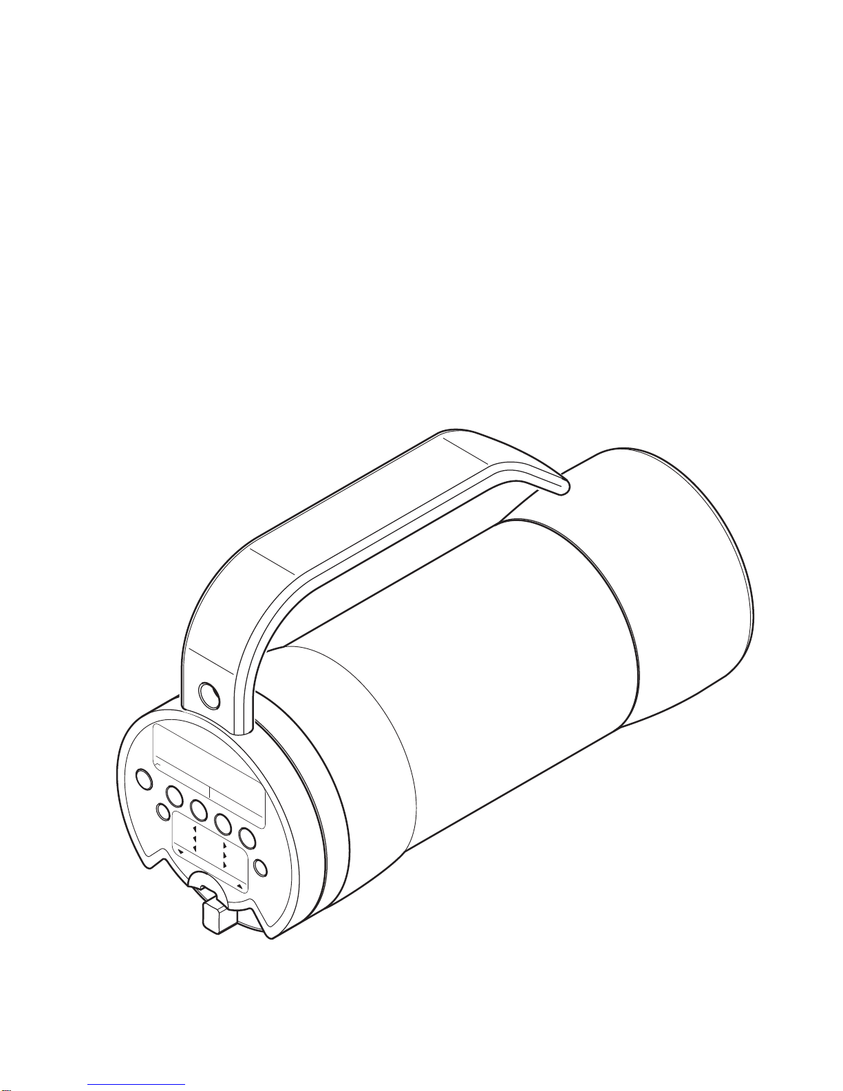
Underwater Hand Lamp
Hartenberger
nano compact
pressure indicator LED power control
unlock lock
OFF
-25%
LED
125%
+25%
SOS
1 sec.
0.5 sec.
5 sec.
nano compact
©Hartenberger Unterwassertechnische Geräte GmbH Rights reserved for technical changes. Issue 01.2011
2
Instructions for use Hartenberger High-Tech-UW-Lamp nano compact
CONTENTS
WARNING SIGNS...................................................................................................... 2
SAFETY WARNING ................................................................................................... 3
GUARANTEE ............................................................................................................. 3
APPLICATIONS.......................................................................................................... 3
ARTICLE DESCRIPTION HOUSING ......................................................................... 4
ARTICLE DESCRIPTION POWER PACK.................................................................. 6
TECHNICAL SPECIFICATIONS................................................................................. 6
FRONT HOUSING COVER........................................................................................ 7
BULB/LED .................................................................................................................. 8
THE REAR HOUSING COVER.................................................................................. 9
POWER PACK ......................................................................................................... 11
PREPARATION FOR USE....................................................................................... 11
USING THE UNDERWATER LAMP......................................................................... 12
TRANSPORT............................................................................................................ 15
STORAGE................................................................................................................ 16
CHARGING .............................................................................................................. 16
CHARGER OFF-SHORE I/6..................................................................................... 19
CHARGER OFF-SHORE II....................................................................................... 20
CARE AND MAINTENANCE.................................................................................... 21
FAULT DIAGNOSIS ................................................................................................. 22
SPARE PARTS......................................................................................................... 23
ACCESSORIES........................................................................................................ 23
WARNING SIGNS
!
If not adhered to the parts of this instruction for use, which are marked with
the above warning sign, there is a danger of property damages or physical
damages.
!
If not adhered to the parts of this instruction for use, which are marked with
the addition “Warning”, there is a great danger of property damages,
physical damages or death.
Warning !
©Hartenberger Unterwassertechnische Geräte GmbH Rights reserved for technical changes. Issue 01.2011
3
Instructions for use Hartenberger High-Tech-UW-Lamp nano compact
SAFETY WARNING
Before attempting to use the underwater lamp, carefully read and
adhere to these instructions for use.
The use of the underwater lamp nano compact calls for the same amount of care
and conscientiousness as is necessary in order to practice diving in a safe
manner. If the instructions are not followed, there is a great danger of personal
injury as well as injury to property (danger of explosion).
GUARANTEE
When these instructions for use and the care and maintenance guidelines are
adhered to, we will guarantee all mechanical parts made from steel, aluminium,
glass and plastic for a period of 5 years against manufacturer’s defects and
material failure. All electronic parts are guaranteed for a period of 2 years. The
rechargeable cells have a guarantee against manufacturer’s defects and material
failure for 6 months. Halogen bulbs and O-ring seals are expendable items and
are therefore not covered by the guarantee. Any unauthorised work on the lamp,
i.e. the removal or tightening of screws, or the removal of the guarantee seals,
will make the guarantee invalid.
Warning !
The manufacturer’s warranty expires if the these instructions for use are
not followed and strictly adhered to. If the lamp is tampered with or
dismantled in part or full by an unauthorised workshop or technician, the
warranty automatically expires, such tampering includes but is not limited
to; loosening and/or tightening screws, the removal/damage of original
seals. When purchasing the lamp make sure that the original
manufacturer’s seals are intact
(1x housing electronics, 1 x cell electronics, charger off-shore II).
Warning !
If the lamp is tampered with and/or if unauthorised (from the manufacturer)
parts/components (e.g. cells, electronics components, non-original
chargers,) are used or installed in the lamp, this results in a change of
original design and the warranty is automatically invalid.
The manufacturer is also released from any product liability.
APPLICATIONS
Warning !
The nano compact underwater lamps are for use in underwater lighting
applications.
Using the lamp in an environment other than water can lead to an
overheating and consequently to a danger of explosion.
In special cases please ask the manufacturer for release.
!
!
!
!

©Hartenberger Unterwassertechnische Geräte GmbH Rights reserved for technical changes. Issue 01.2011
4
Instructions for use Hartenberger High-Tech-UW-Lamp nano compact
ARTICLE DESCRIPTION HOUSING
A
FRONT SEAL / FRONT GLASS PLATE
The front glass plate with the 0-ring (48 x 3 60°hardness) is pressed into the
housing during the assembly by the manufacturer. It can only be opened by
an authorised workshop.
B
FRONT COVER (REFLECTOR COVER)
The standard front cover is equipped with a spot reflector for use with halogen
bulbs. Flood reflectors and/or chemically matt coated front glasses are
available as options.
C
FRONT HOUSING COVER (LED-CONNECTION)
The front housing cover is also available with 4 x 3 Watt LED spots as an
option.
D
PLUG MODULE FOR LED OPERATION
The LED plug module is plugged in to the halogen bulb socket when the lamp
is to be used with LEDs.
EF
O-RINGS
40 x 3,0 and 48x1,6 mm 50°hardness
G
HOUSING / BODY
The housing / body is sealed with the front and the rear screw fitting.
HI
O-RINGS
40 x 3,0 and 48x1,6 mm 50°hardness.
Fig. 1: housing

©Hartenberger Unterwassertechnische Geräte GmbH Rights reserved for technical changes. Issue 01.2011
5
Instructions for use Hartenberger High-Tech-UW-Lamp nano compact
J
SPARE-O-RING
The spare O-ring (48 x 1,6 50°hardness) is located in the rear cover adjacent
to the plastic cover.
K
PLUG-IN CONNECTION
The plug in connection serves as an electrical and mechanical connection
between the power pack and the electronic control panel.
L
REAR HOUSING COVER
The rear housing cover can be removed for accessing/removing/replacing the
cells pack and/or the halogen bulb.
M
CHARGING CONTACTS
The charging contacts are for charging the cell pack while the housing is
closed. The contacts are colour coded: +/red (right contact) and -/blue (left
contact).
N
MAGENTIC SWITCH / TRANSPORT LOCK
The magnetic switch is used for all the control functions of the lamp and the
electronics. To lock the lamp and prevent inadvertent operation, the magnetic
switch, press the switch „in“. This is the so-called transport setting.
O
LED DISPLAY
The 4 LEDs show the brightness set and the remaining capacity of the cell
pack.
P
OVERPRESSURE INDICATOR
If the pin protrudes from the housing, and over pressure exists in the housing.
Q
HOLE FOR A LANYARD
The hole in the handle provides an attachment point for a lanyard for better
security during use and may prevent loss of the lamp.
R
HANDLE
The handle provides a good hold on the lamp, even when wearing thick
neoprene gloves or mittens. If required for video mounting, the handle can be
drilled and an M8 thread cut for mounting to video rigs.

©Hartenberger Unterwassertechnische Geräte GmbH Rights reserved for technical changes. Issue 01.2011
6
Instructions for use Hartenberger High-Tech-UW-Lamp nano compact
ARTICLE DESCRIPTION POWER PACK
S
HALOGEN BULB
The 6V Halogen bulb is plugged into the G4 socket. The bulb can be removed
for replacement or as a precaution during transport by simply pulling it out of
the socket.
T
SPARE-O-RING
The O-ring (40 x 3,0 50°Hardness) is located in a groove in the power pack.
U
HALOGEN BULB STOWAGE
The halogen bulb stowage compartments can be used for storing spare bulbs
and/or stowing the bulb during transport.
V
CELL PACK
The cell pack is plugged in to the power pack and can be removed/replaced
in seconds. The cell pack consists of a Lithium Manganese (LiMn) cell block,
a micro processor electronic and the socket for the halogen bulb including
stowage for 2 halogen bulbs.
W
CONTACT PINS
The contact pins serve as an electrical and mechanical connection between
the power pack and the housing electronic module and for charging the cell
pack.
TECHNICAL SPECIFICATIONS
APPROX. BURN TIME IN MINUTES WITH LIMN CELL PACK 7,2V / 3,8AH
Halogen Bulb 6V 10W 20W 30W LED 4x3W
LED 9x2,5W (R)
Time of use at 50% 260 130 80 150 80
Time of use at 75% 200 100 60 120 60
Time of use at 100%
130 65 40 75 40
Time of use at 125%
100 50 30 60 30
Hartenberger
nano compact
S
T
U
W
V
Fig. 2: power pack

©Hartenberger Unterwassertechnische Geräte GmbH Rights reserved for technical changes. Issue 01.2011
7
Instructions for use Hartenberger High-Tech-UW-Lamp nano compact
The bold printed figures represent the burn times with the standard bulbs as
supplied with the lamp from the manufacturer.
Halogen bulbs available in retail outlets often need up to 10% more power as
stated. The stated burn times will therefore be shortened.
Low ambient temperature have little effect on lithium manganese cells. These
special cells have approx 95% capacity in water temperatures between
0°and 5°Celsius (32°- 41°Fahrenheit).
A 3% - 10% reduction in performance over 12 Months can be regarded as normal
life reduction.
DIMENSIONS/WEIGHT/PRESSURE RATING
Length & Diameter weight on land weight in water Resistance to
water Pressure
150mm x 59mm
6” x 2½“ 0.6kg
1lb 5oz 0.2kg
7oz 100m
330 ft
FRONT GLASS PLATE
The nano compact lamps have a tempered glass plate as standard. This glass
plate has a temperature shock resistance of 150°C (300°F). It is therefore
possible to use the lamps above and under water. A rapid cooling of a heated
front glass is no problem (for example if used temporarily above water in order
to orientate oneself on the surface of the water).
FRONT HOUSING COVER
FRONT GLASS COVER
The O-ring (40 x 3,0 60°hardness) seals the front glass plate in the cover and
is specially pressed into the cover by the manufacturer. This O-ring must be
replaced every 5 years, or earlier if it is shows sign of deterioration (such as
cracking). This job may only be carried out by an authorised workshop
Fig. 3: Opening the front screw fitting

©Hartenberger Unterwassertechnische Geräte GmbH Rights reserved for technical changes. Issue 01.2011
8
Instructions for use Hartenberger High-Tech-UW-Lamp nano compact
REMOVING THE FRONT HOUSING COVER
The front housing cover can be removed by unscrewing the cover anti-clockwise
from the housing (thread length approx 10mm) see Fig. 3. To avoid damage to
the halogen bulb, pull the front cover straight away from the housing.
CLOSING THE HOUSING
Before closing the housing, all threads, sealing surfaces and seals must be
checked for integrity and cleanliness. Should the sealing surfaces and/or
components be contaminated, then the O-rings (40 x 3,0 50°hardness and
48 x 1,6 50°hardness) and its groove should be thoroughly cleaned. Should the
sealing surfaces and/or components be damaged, then all damaged parts should
be replaced. If the O-ring is removed, care must be taken not to damage the
groove in which the O-ring sits. A soft blunt tool should be used for the removal of
the O-ring, i.e. a wooden tooth pick. Before the components are refitted it is
recommended that a thin coating of silicone grease is applied as lubrication. It is
recommended that after such work has been carried out, that the seal/integrity of
the housing is first checked underwater without the power pack fitted. The
housing is then closed by screwing the components clockwise together. The
screw fitting should be tightened by hand only until the parts are mated together.
MAINTENANCE OF THE REFLECTOR
If the reflector mirror becomes dirty or is contaminated, it must be cleaned with a
soft, dry cloth. Remove the front housing cover and then the reflector can be
removed. First remove the O-ring (∅3mm, 50°hardness) using a blunt tool such
as a tooth pick or similar, care must be taken not to damage the O-ring. Once the
reflector has been cleaned, the O-ring can be refitted into the groove between the
reflector and the housing cover, make sure the O-ring sits correctly into the
groove, a blunt tool can be used for pressing the O-ring into the groove.
BULB/LED
Fig. 4: Removal/Refitting the bulb

©Hartenberger Unterwassertechnische Geräte GmbH Rights reserved for technical changes. Issue 01.2011
9
Instructions for use Hartenberger High-Tech-UW-Lamp nano compact
REMOVING / REPLACING THE HALOGEN BULB
The halogen bulb is accessible after opening the front and rear housing covers.
Access to the halogen bulb stowage is easier when the rear housing cover is
opened (see page 8).
RISK OF INJURY THROUGH BURNING!
The halogen bulb remains very hot for an extended period of time after use!
Do not touch the halogen bulb with your bare fingers. Residue on your fingers can
remain on the glass during normal use may form carbon. This will reduce the
efficiency of the bulb. Use a clean cloth or tissue to remove the bulb from the
socket. When refitting or replacing the bulb, ensure that it is located all the way
into the socket. To produce an even illumination, it is imperative to ensure that the
bulb sits upright in the socket. Assemble the lamp and check for correct fit and
operation.
To prevent plastic components and the cells of the lamp from overheating
and becoming damaged by heat, the halogen bulb should only be switched
on when the housing is completely assembled and all covers are screwed
tight.
SPARE HALOGEN BULB
There are 2 halogen bulb stowage compartments adjacent to the bulb socket.
Bulbs are safely stowed in these compartments and the plastic cover prevents
them from inadvertently falling out. This cover must be turned open to access the
bulb stowage (see Fig.4, II).
LED MODULE
The optional LED-Module replaces the standard halogen bulb and front
cover/reflector. The module is connected electrically by plugging it into the
halogen bulb socket. (see fig. 4, III). The plug arrangement prevents incorrect
fitting/connection. If the lamp does not function properly, remove the plug module,
rotate it 180°and refit it into the halogen bulb socket. Take care not to short
circuit the contacts.
REAR HOUSING COVER (THREADED CAP)
THE REAR HOUSING COVER SEALS
The double O-ring seals on the charging socket, the over pressure indicator and
the lamp conductor insert can only be replaced by the manufacturer.
Based on the experience gained to date, this service work should be carried out
every 4-5 years (with intensive use in diving schools, every 3 years).
Our experience with other models indicates that these seals are in good condition
after this period.
Please get the latest information from our web site
(http://www.hartenberger.de/pdf/e_bet_nano.pdf) on service intervals and
recommended life spans the can change with time/experience.
The plastic components on the rear housing cover should not be exposed
to any solvent based agents, such exposure may result in cracks in the
components and subsequent leakage/flooding.
!
!
!

©Hartenberger Unterwassertechnische Geräte GmbH Rights reserved for technical changes. Issue 01.2011
10
Instructions for use Hartenberger High-Tech-UW-Lamp nano compact
OPENING THE REAR SCREW FITTING
The housing is opened by unscrewing the fitting anti-clockwise, (thread length
approx. 10 mm [3/8“]). Whilst opening the housing, it should be held in an upright
position, thus preventing the power pack from inadvertently falling out.
CLOSING THE REAR SCREW FITTING
Before closing the rear screw fitting, all threads, sealing surfaces and seals must
be checked for integrity and cleanliness. Should the sealing surfaces and/or
components be contaminated, then the O-rings and its groove should be
thoroughly cleaned. Should the sealing surfaces and/or components be
damaged, then all damaged parts should be replaced. If the O-ring (40 x 3,0
50°hardness and 48 x 1,6 50°hardness) is removed , care must be taken not to
damage the groove in which the O-ring sits. A soft blunt tool should be used for
the removal of the O-ring, i.e. a wooden tooth pick. Before the components are
refitted it is recommended that a thin coating of silicone grease is applied as
lubrication. It is recommended that after such work has been carried out, that the
seal/integrity of the housing is first checked underwater without the power pack
fitted. The housing is then closed by screwing the components clockwise
together. The screw fitting should be tightened by hand only until the parts are
mated together.
Fig. 5: Opening the rear screw fitting
©Hartenberger Unterwassertechnische Geräte GmbH Rights reserved for technical changes. Issue 01.2011
11
Instructions for use Hartenberger High-Tech-UW-Lamp nano compact
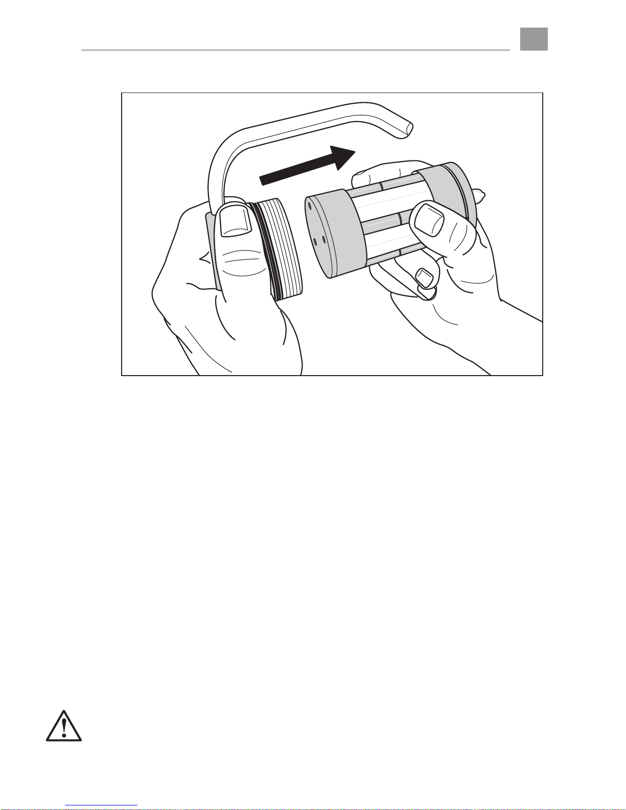
POWER PACK
REMOVING THE CELL PACK
After removing the rear housing cover (see page 10), the complete cell pack can
be unplugged and removed (Fig. 6).
The 3 pins serve as the mechanical and electrical connection between the cell
pack electronics and the housing electronics.
There is stowage for a spare housing O Ring (48 x 1,6 50°hardness) located in
the rear housing cover (adjacent to the plastic cover).
FITTING THE CELL PACK
Hold the rear housing cover upwards and carefully plug the cell pack onto the
rear housing cover. Ensure that the 3 plugs on the rear housing cover are guided
into the sockets carefully. The plug arrangement prevents incorrect connection.
Push the cell pack fully down on to the pins without damaging/distorting the pins
and without use of excessive force.
PREPARATION FOR USE
BEFORE THE LAMP IS USED FOR THE FIRST TIME
Before the first use, the cells must be charged. Hartenberger underwater lamps
are manufactured to a high degree of precision and each lamp is tested to a
water pressure of 10 bars. The condition of the lamp and in particular the housing
and sealing rings should however be checked before the first use (see page 8).
Warning !
Due to damage during transportation or hidden material defects, leakage
can occur (not the fault of the manufacturer). To check if the housing is
pressure tight, the first dive should be carried out without the housing
insert, i.e. empty.
Fig. 6: Removal of the power pack
!
©Hartenberger Unterwassertechnische Geräte GmbH Rights reserved for technical changes. Issue 01.2011
12
Instructions for use Hartenberger High-Tech-UW-Lamp nano compact
BEFORE EACH USE
Before each use, the threads, sealing surfaces and O-ring must be checked for
integrity and cleanliness. (See Closing the housing, page 8). If the bulb has been
removed for transport, it should be refitted into the socket. Refit the halogen bulb
in the socket which may have been removed for transportation. Only release the
transport lock to the unlocked position immediately before use. (See page 12).
USING THE UNDERWATER LAMP
Warning !
When the lamp is turned on, direct the beam away from yourself and others.
Do not point the beam directly at others. If there is a defect on the lamp, the
front glass plate may be forced out of the front of the housing with
explosive force.
Warning !
Water inside the housing (especially sea water) can have drastic results
consequences after some a period if time. Therefore, during the use of the
lamp please check repeatedly, whether water has found its way inside. Do
this by holding the lamp on the slant pointing down, thus the ray of light
pointing away from the body. Then look at the front glass from the side.
If there is water inside the housing, bring the dive to an end by following the
diving rules and open the housing as soon as possible (see page 22).
TRANSPORT LOCK
Release the transport lock immediately before use.
To unlock the switch, push it from the transport lock position (lock) outwards
(unlock) the switch must physically click into the unlocked position.
MAGENTIC SWITCH / SWITCH UNIT
The electronic controls are activated by pushing the switch to the right (+) or to
the left (-). The signals are transmitted via magnetically sensitive hall sensors.
This feature avoids any mechanical connection through the lamp’s housing
reducing the risk of water ingress and general wear.
ACTIVATING THE ELECTRONICS / CELL PACK CAPACITY DISPLAY
If the switch is pushed to the left (-) for approx. 3 seconds, the electronics are
activated from the energy saving „sleep” mode. The LED display illuminates and
shows the charge status of the cell pack for approx 3 seconds.
One LED = 25%, two LED´s = 50%, three LED´s = 75%, four LED´s = 100%
To view the capacity display after the 3 seconds, Slide the switch one short push
to the left (-) again.
If the lamp is not used for a period of 10 hours, the electronics will automatically
return to the energy saving “sleep” mode.
BRIGHTNESS / DIMMER
The electronics allow the lamp to be used in 4 levels of brightness (50%, 75%,
100% and using over voltage; 125%).
Using the lamp at dimmed (lower) settings will save energy and extend the burn
time of the lamp with one charge.
If the switch is pushed for a short time (approx ½ second) to the right (+), the
lamp will turn on to the first brightness stage (50%).
Each subsequent push to the right (+) will increase the brightness 25%.
Each subsequent push to the left (-) will decrease the brightness 25%.
!
!

©Hartenberger Unterwassertechnische Geräte GmbH Rights reserved for technical changes. Issue 01.2011
13
Instructions for use Hartenberger High-Tech-UW-Lamp nano compact
If the switch is pushed to the right (+) for longer (approx. 1 second), the lamp will
turn on to the highest brightness stage (125%).
If the switch is pushed for approx 1 second to the left, the lamp will switch off
immediately.
If the switched is pressed down for approx. 3 seconds, the LEDs will show the
brightness currently set.
One LED = 50%, two LED´s = 75%, three LED´s = 100%, four LED´s = 125%
After another 3 seconds, the display then indicates the current cell pack capacity.
When the lamp is turned off, the LED display will also switch off. Sliding the
switch to the left will then activate the LED display and shows the current cell
pack capacity, this remains visible for approx 3 seconds.
SOS WARNING / DISTRESS SIGNAL
The electronics have the facility to transmit an SOS signal in Morse alphabet
(2 x short, 3 x long, 3 x short).
If the switched is pressed for an extended time (approx. 5 seconds) to the right
(+), this function is activated and the lamp begins to blink SOS.
Pressing the switch to the left (-) for approx. 1 seconds stops the SOS signal.
The time that the lamp will generate the SOS signal is approx. 3 times longer than
the continuous burning time of the halogen bulb fitted. When the cell pack is
almost fully discharged, the SOS signal will fade and dim. Only use the SOS
function in a distress or emergency situation. If the lamp fades, turn the
signal off and only turn it back on when help is in sight.
EMERGENCY LIGHTING (AUTOMATIC)
The lamp’s electronics will automatically sense a defective bulb and will
automatically turn on all the LEDs. This serves as an emergency source of light
for reading instrumentation or for orientation in a very dark environment. To turn
the emergency lighting off, push the switch to the left (-). Pushing the switch to
the right (+) will reactivate the emergency light.
EMERGENCY LIGHTING (MANUAL)
The emergency light (all 4 LEDs are illuminated continuously) may be activated
manually. Push the switch to the left for approx. 5 seconds. This emergency light
will last longer than the normal bulb burning time and will provide you with an
emergency source of light for reading instrumentation or for orientation in a very
dark environment. To turn the emergency lighting off, push the switch to the
left (-). The emergency light function will not activate after the lamp has turned off
automatically in the discharge protection mode.
OVER-VOLTAGE / DIMMER
The HLX bulbs which we use have a much greater efficiency than standard
halogen bulbs. Using a 6 cell power pack, we have a power supply of 7,2 volts.
This allows the 6v bulb to be operated continuusly with an over-voltage of approx.
6,8 volts. The electronics switch the bulb on slowly thus preventing the coil in the
bulb from burning out. The resulting increase in brightness is approx. 30% more
than the stated power. The micro controller can accurately monitor the energy
dissipation to the bulb and ensures a continuous colour temperature over the
entire discharge process and operation. The life expectancy of the bulb of approx.
100 hours is not reduced. Using the lamp at reduced power settings saves energy
and extends the burning time in a single charge cycle. Permanently operating the
lamp at reduced power settings will however produce a grey coating on the bulb’s

©Hartenberger Unterwassertechnische Geräte GmbH Rights reserved for technical changes. Issue 01.2011
14
Instructions for use Hartenberger High-Tech-UW-Lamp nano compact
glass. If reduced brightness is required on an extended basis, then a lower power
rating halogen bulb is recommended.
LOW LEVEL CAPACITY WARNING
When the lamp blinks 3 times, the user is warned of the immanent end of the
burn time of the lamp. When the lamp is being used with the standard 20 watt
halogen bulb at 100% power, this will be approximately 10 minutes after the
3 blinks. If applicable, you should abort the dive as fast as possible and turn the
lamp off (reduce the power setting).
Further use of the lamp will increase the wear and tear on the cells and
reduce their life expectancy.
DISCHARGE WARNING
Warning !
At the latest, the lamp should be turned off and no longer operated when it
starts to blink continuously. Further use of the lamp will damage the cells
and should only be practised in an emergency.
The duration of blinking with the standard halogen bulb set at 100% power is
approx. 1-2 minutes. If the lamp is switched over to 25% power, then approx.
3 minutes of continuous light is available. After this, the light will go into a blinking
mode once again.
DISCHARGE PROTECTION
Warning !
The discharge protection will turn shut down the lamp after the continuous
blinking. In the case of an emergency where light is necessary, the lamp (if
possible after a short pause) can be reactivated and will automatically turn
on at 25% power setting. The cells are almost certainly damaged should
this mode of operation be selected.
If the blinking stops or if the light becomes visibly weaker and has a yellow
tint, then there is probably an error in the electronics. Stop operating the
lamp as soon as possible and return it to the manufacturer for
evaluation/repair.
Due to the previously mentioned risks of damage to the cell pack as a result
of severe discharge, the lamp should never be operated without constant
supervision and control.
TEMPERATURE MONITORING AND WARNING
During operation, the electronics constantly monitor the temperature of the cells.
If the temperature exceeds 60°C (140°F), a warning will be generated and the
LED display will begin to blink quickly (4 x per second) and the power of the lamp
will automatically reduce to 25%. If this occurs, shut off the lamp and allow it to
cool down (unless in an emergency situation where the lamp is necessary).
Return the lamp to the manufacturer for evaluation.
If this function does not activate, a secondary monitoring will shut down the lamp
(halogen bulb and LED display) at 75°C (167°F). In this case, the lamp cannot be
operated any more. Return the lamp to the manufacturer or replace the cell pack
with a new unit.
WATER INGRESS WARNING
If a substantial amount of water enters the lamp and reaches the power pack
circuit board, a warning will be generated; the LED display will begin to blink
quickly (4 x per second) and the power of the lamp will automatically reduce to
25%.
!
!
!

©Hartenberger Unterwassertechnische Geräte GmbH Rights reserved for technical changes. Issue 01.2011
15
Instructions for use Hartenberger High-Tech-UW-Lamp nano compact
Warning!
Terminate the dive following standard safe diving practices and open the
housing as soon as possible.
An extended period of flooding, in particular salt water flooding, may cause
a failure of this warning function.
OVER PRESSURE WARNING
If the pressure inside the housing increases (e.g. as a result of gas production
due to electrolysis after flooding and/or if the cell(s) are defective), an over
pressure indicator in the form of a small plug located to the left of the LED display
will protrude approx 6mm (¼”) from the housing. The LED display will begin to
blink quickly (4 x per second) and as a safety precaution the power of the lamp
will automatically reduce to 25%. Turn off the lamp as soon as possible.
Warning!
Terminate the dive following standard safe diving practices and open up the
housing as soon as possible, (see page 22).
AFTER USE
Warning!
After the dive is completed, examine the lamp for signs of flooding or water
ingress as soon as possible. To carry out this check, hold the lamp upside
down with the glass plate pointing down and look at the glass plate from
the side for any signs of moisture/water ingress.
After each use, the lamp should be thoroughly rinsed in clean, fresh water. During
this rinsing, operate the switch in all directions to rinse under the switch.
When the lamp is operating, the temperature in the housing will increase and a
slight overpressure will form inside the housing. If the housing is opened
immediately after use, this slight overpressure will cause excessive friction on the
threads of the covers and/or the O-ring seals, the cover will be difficult to open.
For this reason we recommend that the lamp is left unopened (unless flooding
has occurred) for several minutes after it is switched off.
TRANSPORT
After use, the switch should be locked in the off position to prevent
inadvertent operation/use. To lock the switch in the off position, push the
switch towards the LED display, it should click into the transport lock
position. When correctly locked, the switch cannot be pushed to the left or
right.
Warning !
If the lamp is to be transported or stored without direct supervision, the
halogen bulb must be removed from the socket and stowed (see page 9).
This is a precaution in case a defective electronic module turns the lamp
on. This heat generated by the halogen bulb my cause damage to items
adjacent to the lamp/glass/bulb.
!
!
!
!
!
©Hartenberger Unterwassertechnische Geräte GmbH Rights reserved for technical changes. Issue 01.2011
16
Instructions for use Hartenberger High-Tech-UW-Lamp nano compact
STORAGE
For extended periods of storage, the cell pack should be removed, the halogen
lamp removed from the socket and stowed and the housing should be closed.
Place the cell pack on a suitable surface (non sensitive) and store in a dry
environment between 10°- 20°C (50 – 68°F). Under n o circumstances should the
lamp be subjected to temperatures above 45°C (110°F ). If a cell pack is
continuously stored at full charge and increased temperatures, the cell pack will
suffer from an irreversible reduction of capacity of more than 10% per year.
If the cell pack is to be stored for an extended period of time, the cell pack
should be stored at a low temperature with a capacity of 50-60%.
The irreversible loss of capacity due to natural loss of capacity over time can be
reduced to as little as 3% with good care and attention. The lithium manganese
cells are subject to a very small natural discharge (depending on the ambient
temperature this is approx. 4-8% per month, and the electronic in the lamp that
monitor the conditions result in approx. 3% discharge per month).
If the cell pack is stored for extended periods of time, it should be
recharged every 4-6 months to approx. 50-60% capacity.
A completely discharged cell pack is protected by the electronic monitoring
that prevents further charging. In this case, return the cell pack to the
manufacturer for evaluation.
CHARGING
GENERAL INFORMATION CONCERNING CHARGING RE-CHARGEABLE CELLS
The lithium manganese re-chargeable cells used in this lamp have been
declared as gas and acid/alkali sealed. For this reason the electrolyte in the cells
cannot escape and the cells can be charged regardless of their environment. This
positive feature has been stated by the cell manufacturer but an exception to this
cannot be ruled out.
Re-chargeable cells can, if defective, produce an internal pressure in the
cell during charging/discharging (use) that may cause the over pressure
device integrated in the cell to open. This in turn will allow electrolyte to escape
from the cell. Electrolyte is an aggressive alkali and also conducts electrical
current, this will destroy the cell over time. The resulting electrolysis will create an
over-pressure inside the housing of the lamp.
Warning !
In case of a defective cell, the lamp is equipped with a mechanical and
electronic over pressure indicator. After charging the lamp with the housing
closed, check these indicators and ensure that there is no over pressure
inside the housing. (see page 15).
MEMORY-EFFECT
The so-called memory effect will occur when re-chargeable cells are regularly
charged in a partly discharged state (for example this occurs when a wireless
telephone is placed in the charging station every evening). The popular rule of
thumb to only charge re-chargeable cells when they are completed discharged is
applicable to NC (nickel cadmium) or NMH (nickel metal hydride) cells. This rule
does not apply to underwater lamps with high discharge currents, in this case, the
regular full discharge has a negative effect on the cells. The lithium manganese
cells used in this lamp do not have a memory effect.
Warning !
Regularly discharging a multi cell power pack may damage the voltage
!
!
!

©Hartenberger Unterwassertechnische Geräte GmbH Rights reserved for technical changes. Issue 01.2011
17
Instructions for use Hartenberger High-Tech-UW-Lamp nano compact
features of individual cells within the cell pack, thus causing an unbalance
within the cell pack that in turn may cause the weakest (and therefore the
most susceptible) cell to fail prematurely. The more often the cell pack is
discharged to the pint where the discharge protection cuts in, the greater
the chance that an individual cell will fail within the cell pack.
PREPARATION FOR CHARGING
There are two methods for charging the lamp.
I. INTERNAL CHARGING CONNECTION
The charging connection is located on the cell pack, the cell pack must be
removed for charging.
This is the preferred method of charging as the cell pack can be seen and
monitored during the charging process.
Open the rear cover on the lamp housing and remove the power pack (see
page 10).
The charging connections are marked with + (red/right contact) and – (blue/left
contact).
Charge the cell pack in a cool dry environment (ideally 10-20°C / 50 – 68°F). The
ambient temperature should never exceed 40°C (104°F ). If the cell pack is warm
to touch (above 40°C / 104°F) then allow the cell p ack to cool down before
charging.
Warning !
The charging process requires a mains power supply socket close to the
cell pack and the cell pack should be placed on a dry surface that is not
sensitive. (Even gas tight lithium manganese cells may leak under certain
conditions, this leakage may cause damage to the surface the cell pack is
placed on).
Note that a defective electronic module may cause the lamp to turn on
during charging. Damage to adjacent material caused by the resulting heat
generated by the halogen bulb must be avoided. For this reason we
recommend that the halogen bulb is removed during charging.
Warning !
Check the condition of the charging sockets and cell pack regularly and
examine for signs of corrosion, oxidation of leakage. Examine the sleeves
surrounding the cells for signs of bubbling or traces of a white, floury
residue between the cells in the cell pack. In any of the above conditions
are found, do not charge the cell pack ! Return the lamp to the manufacturer
for evaluation, pack the cell pack and the housing separately.
Warning !
The temperature of the individual cells should also be checked regularly by
feeling the temperature during charging. If one or more cells is hot to touch
then this may indicate a defective cell or cell pack. Do not use this cell
pack, return it to the manufacturer for evaluation or replace the cell pack
with a new one.
II. EXTERNAL CHARGING CONNECTION
The charging connection is on the outside of the housing, the cell pack remains in
the lamp housing during charging.
This method of charging is advantageous when the ambient conditions are
unsuitable for opening the housing, the cell pack is charged via the external
connections located on the rear of the housing.
!
!
!

©Hartenberger Unterwassertechnische Geräte GmbH Rights reserved for technical changes. Issue 01.2011
18
Instructions for use Hartenberger High-Tech-UW-Lamp nano compact
The charging connections are marked with + (red/right contact) and – (blue/left
contact).
Because the cell pack cannot be examined whilst using this method of
charging, we recommend that it should only be carried out in exceptional
circumstances. After the lamp has been charged repeatedly using the
external charging connections, the cell pack must be examined for signs of
damage/deterioration !
Before the plugs are plugged into the charging connections, the sockets
must be thoroughly cleaned and dried (e.g. with an air blast or with a Q Tip).
Moisture can lead to oxidation and/or charring of the connections during
charging.
The ambient temperature should not exceed 40°C (104°F) during the charging
process. If the lamp has been in direct sunlight and is warm to touch (above 40°C
/ 104°F) then cool the lamp down before charging.
Warning !
The charging process requires a mains power supply socket close to the
cell pack and the cell pack should be placed on a dry surface that is not
sensitive. Note that a defective electronic module may cause the lamp to
turn on during charging. Damage to adjacent material caused by the
resulting heat generated by the halogen bulb must be avoided.
MONITORING DURING CHARGING
The control module in the lamp monitors the temperature of the cell pack during
charging. If the temperature of the cell pack exceeds 60°C (140°F) during
charging, the charge process will be automatically stopped and the LED display
will blink (4 x per second).
INDICATIONS ON THE LED DISPLAY DURING CHARGING
When the lamp is being charged using the external charging connections, the
LED display will show the current capacity status of the cell pack. The actual
charging process is indicated by the last LED blinking approx 2 x per second.
When the cell pack is fully charged, the electronic module automatically shuts off
the charger and all 4 LEDs are off. Within 1 hour, the electronic module will re-
start the charging process approx 2 or 3 times to „top-up“ the cell pack to the
max. capacity (approx 2-3% top-up charge).
NON-ORIGINAL CHARGERS
Warning !
Only chargers that have been approved by the manufacturer in advance of
use may be used for charging the lamp. Using non-approved chargers,
voids the manufacturer’s warranty.
Use of non-original chargers may damage the electronic module that
monitors the cell pack condition. The cells can overheat and/or be
damaged. (Risk of explosion !).
Use of chargers that are not previously approved by the manufacturer is
an alteration to the original design.
This voids the warranty and any releases the manufacturer of any
responsibility and liability for subsequent damage and/or injury.
CHARGER OFF-SHORE I/6
Use only manufacturer approved cells, do not connect any non-approved
cells.
!
!
!

©Hartenberger Unterwassertechnische Geräte GmbH Rights reserved for technical changes. Issue 01.2011
19
Instructions for use Hartenberger High-Tech-UW-Lamp nano compact
The charger off-shore 1/6 is suitable for charging the High-Tech-mini lamp nano
compact.
The max. charging current is approx. 1.1 Amps.
The charging time for the nano compact is approx. 3 hours.
The charger uses the latest technology with a wide range input voltage rating and
accepts any voltage between 100 and 250V and frequencies between 45 and 65
Hz. It is not necessary to mechanically pre-select the local voltage. All
Hartenberger cell packs with 5-6 cells (6 – 7.2V) are identified by the charger
when connected and will have an optimal; efficient charge.
When charging the nano compact lamp, the cell pack monitoring is carried
out by the electronic module in the cell pack.
First connect the charging cable to the charger using the chinch plug. The
charging cable is plugged into the charging sockets on the lamp with banana
plugs. When connecting the cable(s) to the lamp and/or charger, guide the plugs
straight into the sockets and do not use excessive force. Ensure the correct plug
is connected in to the charging socket, follow the colour coding and labelling
(red/+ on the right, blue/- on the left )
The charger is initiated when the mains is connected (plugging the charger into
the mains socket). The charger is equipped with a standard euro 2 pin flat plug.
Other popular plug configurations are available and replace the euro plug simply
by pulling it out and fitting the plug desired.
Avoid short circuiting the plug pins (e.g. with a metal object crossed over
the two pins). Ensure the charger is dry and away from moisture and the
cooling slots are not covered or restricted particularly in extreme
climates/conditions.
All the functions of the charger are displayed via a single LED.
Charger LED when charging NC or NMH re-chargeable cells:
Red Mains power is connected, cell pack is charging.
Off No mains power or no cell pack connected.
Red blinks slowly Mains power connected, cell pack is fully charged and a
trickle charge is active.
Rot blinks fast Mains power connected, the cell pack is fully discharged and
is being regenerated by the charger.
If fully discharged cell packs are connected, the LED will blink red very fast
(approx. 3 x per second). Stop the charging process after approx. 5 minutes by
isolating the mains power. Resume the charging process after approx 3 minutes.
If the charger repeatedly blinks fast on re-starting the charging process, the cell
pack is probably defective and can/should not be charged).
Charger LED when charging lithium manganese re-chargeable cells:
When the cell pack is fully charged (all 4 LEDs on the nano compact display
of off) the electronic module in the lamp will cut off the charging current to
the lamp. The charger LED is off or may blink irregularly.

©Hartenberger Unterwassertechnische Geräte GmbH Rights reserved for technical changes. Issue 01.2011
20
Instructions for use Hartenberger High-Tech-UW-Lamp nano compact
CHARGER OFF-SHORE II
Use only manufacturer approved cells, do not connect any non-approved
cells.
The charger off-shore 1/6 is suitable for charging the High-Tech-mini lamp nano
compact.
The max. charging current is approx. 1.8 Amps.
The charging time for the nano compact is approx. 2 hours.
The charger uses the latest technology with a wide range input voltage rating and
accepts any voltage between 100 and 250V and frequencies between 45 and 65
Hz. It is not necessary to mechanically pre-select the local voltage. All
Hartenberger cell packs with 5-12 cells (6 – 14.4V) are identified by the charger
when connected and will have an optimal efficient charge.
When charging the nano compact lamp, the cell pack monitoring is carried
out by the electronic module in the cell pack.
First connect the charger to the mains by plugging in the mains cable. All the
functions of the charger are displayed via 2 LEDs. The charger is monitored by a
special electronic module inside the charger. This modules requires 1-1.5
seconds to carry out a self test after which time the LEDs will illuminate.
Charger LEDs when charging NC or NMH re-chargeable cells:
LED I :
Green Mains supply connected, charger is functioning correctly.
Red Mains supply connected, charger is overloaded or defective.
Off No mains supply connected.
Next connect the charging cable to the charger using the chinch plug. The
charging cable is plugged into the charging sockets on the lamp with banana
plugs. When connecting the cable(s) to the lamp and/or charger, guide the plugs
straight into the sockets and do not use excessive force. Ensure the correct plug
is connected in to the charging socket, follow the colour coding and labelling
(red/+ on the right, blue/- on the left )
Avoid short circuiting the plug pins (e.g. with a metal object crossed over
the two pins). Ensure the charger is dry and away from moisture and the
cooling slots are not covered or restricted particularly in extreme
climates/conditions.
LED II :
Red No cell pack connected (pause).
Green blinks Fast charge to 100 % of the cell pack capacity.
Off Trickle charge, cell pack is 100% charged.
Charger LED when charging lithium manganese re-chargeable cells:
When the cell pack is fully charged (all 4 LEDs on the nano compact display
of off) the electronic module in the lamp will cut off the charging current to
the lamp. LED II on the charger will be red (cell pack not connected) or may
blink irregularly
!
Table of contents
Popular Underwater Lighting manuals by other brands


Westfalia
Westfalia Wetelux 96 76 84 instruction manual

EasyPro
EasyPro LED4WWK Instructions for operation

Polarion
Polarion Abyss U Series manual

Sea & Sea
Sea & Sea YS-D3 DUO instruction manual

Hidrotermal
Hidrotermal Mini Series Installation and maintenance manual

LIGMAN
LIGMAN BORNHOLM 2 installation manual