Harvest TEC 600BB User manual

600BB & 600BBHD-20-INST-Imp&Metric
6/20
Installation Manual
Model 600BB & 600BBHD
Moisture Sensor Kit for Large Square Balers
For New Holland BigBaler and Case IH LB 4
Forage Harvester

2
DECLARATION OF INCORPORATION
MANUFACTURER: Harvest Tec Inc.
2821 Harvey St.
P.O. Box 63
Hudson, WI 54016, U.S.A.
REPRESENTATIVE ESTABLISHED IN COMMUNITY: Profitable Farming Company
Middle Barlington, Roborough
Winkleigh, Devon, EX19 8AG
ENGLAND
The person above certifies and declares that:
VIRTUAL MACHINE: Equipment mounted on a farm press and for the application of innoculants onto
forage crops.
MODEL: 600BB & 600BBHD-INST-20-Imp&Metric
BRAND: Harvest Tec
SERIAL NUMBER:
This application preservatives for hay Harvest Tec system meets the Directive 2006/42/EC of the
European Parliment and the Council of 17 May 2006 and other applicable European Directives
including Directive 2004/108/EC on the Electromagnetic compatability.
The application of preservatives for hay Harvest Tec system will be turned on after being installed on
a farm press has been declard in conformity with the Machinery Directive.
Person in the community authorized to provide information on the partly completed machinery and
making this statement:
Richard Snell, President, Profitable Farming Company
Signed on May 21, 2011: Middle Barlington, Roborough
Winkleigh, Devon, EX19 8AG
ENGLAND

3
Table of Contents
PAGE
Introduction
4
System Requirements
4
Tools Needed
4
Installation of the Moisture Sensor Kit
5-8
Installation of Dual Channel Processor (DCP)
5
Installation and Routing Wire Harnesses and Baler Interface Harness
6
Installation of iPad Integration Control
7
iPad Integration control Light Signals
7
Bluetooth Receiver Lights
7
Connecting Star Wheels to the DCP –600BB & 600BBHD
8
Installation of the Star Wheel Moisture Sensors –600BB
9
Installation of Bale Rate Harness –600BB
9
Installation of the Star Wheel Moisture Sensors –600BBHD
10
Installation of Bale Rate Harness –600BBHD
11
Installation of End of Bale Sensor –600BB & 600BBHD
11
Wiring Diagram
12
Pin Outs
13-14
Troubleshooting
15
Parts Breakdown
16-18
Controls and Harnesses
16
Star Wheel Sensors
17
Bale Rate Sensors
17
Optional iPad Display Kit
18
Warranty
19

4
Introduction
Thank you for purchasing this 600BB or 600BBHD Moisture Sensor Kit. The Moisture Sensor Kit is designed to
operator through the baler’s ISOBUS system and/or an Apple iPad (not included) using the Hay App. The
moisture sensor offers these advantages:
1. Operation coordinated with baler operation
2. Less cab clutter providing better visibility
3. Ease of use with all information on one screen
4. Records kept together
5. The system is ready for future updates
This manual will take you through the steps of installing the moisture sensor. Please read this manual carefully
to learn how to install the equipment correctly. Failure to do this can result in personal injury or equipment
malfunction. If you are unsure about installing the system after consulting this manual, contact your local
authorized dealership for additional assistance or look for the contact information on the back cover of this
manual. If you are in need of parts for the system please view the Parts Breakdowns in the back of this manual
and contact your local authorized dealer to order the parts.
Right and Left sides are determined by facing in the direction of forward travel.
System Requirements
The Baler Control Module (BCM)
must have Version 4.2.0.0 or higher.
*Made for iPad®(3rd through Pro 2nd generation), running the current iOS operating system
or one version previous required for iPad option
*iPad is a trademark of Apple Inc., registered in the U.S. and other countries.
**600 Series Applicators with serial number before DCP27000 will require the DCP to be sent to Harvest
Tec for a required update in order to use the iPad Integration Module (030-6672C).
*Hay App version must be at least 2.7.1 (or higher) to operate with the iPad Integration Module
In order for the CNH Baler to receive the messages regarding Status, Moisture and display this information on
the Baler Work Screen, the software in the Baler Control Module (BCM) needs to be updated to version 4.2.0.0
or higher. Dealers can log an ASIST incident and request the BCM software from CNH Technical Support
Services if they need the software prior to those release dates.
Tools Needed
Standard Wrench set
Electric drill and bits
Side cutter
Standard Socket Set
Hammer
Center punch

5
Installation of the Dual Channel Processor (DCP)
1. Locate the Dual Channel Processor (DCP) 006-6671LS.
2. Lock the baler flywheel brake and lift open the front hood.
3. Locate the four holes by the fly wheel brake (Figure 1).
4. Use four 5/16” x 3” hex bolts with four flat washers (positioning bolt heads on the inside of the baler
frame) and secure to the baler with four 1 1/8” threaded standoffs that will be on the outside of the baler
frame, Position four fender washers between the DCP and standoffs (Figure 2).
5. Mount the DCP with the display cable pointed down to the baler (Figure 3). If installing the 600BBHD kit
refer to (Figure 4). *The baler ECU will be partially covered by the DCP.
6. Attach lock washers and hex nuts to mount the DCP to the baler. Do not tighten down yet.
7. Before tightening hardware install the DCP shield (001-5650X) over the top two 5/16” bolts between the
fender washers and the mounting plate of the DCP. Tighten all hex nuts (Figure 5).
Figure 1
Figure 2
Figure 3
Figure 4
Figure 5

6
Installation and Routing Wire Harnesses and Baler Interface Harness
Route harnesses along inside of the
baler (Left). Keep harnesses away from
moving parts and hydraulic hoses.
Secure with existing cable clamps or use
cable ties.
When all connections are made to the
DCP secure wires as shown above to
allow for water to be shed away from the
DCP.
Locate and remove the Active
Terminator (below left) of baler. Attach
Baler Interface Harness (006-6650VA) to
that location. Reconnect Active
Terminator (below) to open port of that
same harness (006-6650VA)

7
Installation of iPad Integration Control
*If not using ISOBUS integration refer to the information below.
Locate a safe location in the cab of the tractor to place the iPad
Integration Control (030-6672C). Recommended location is securely
fastened out of the operators way in a location that is close enough to
reach with the iPad cord.
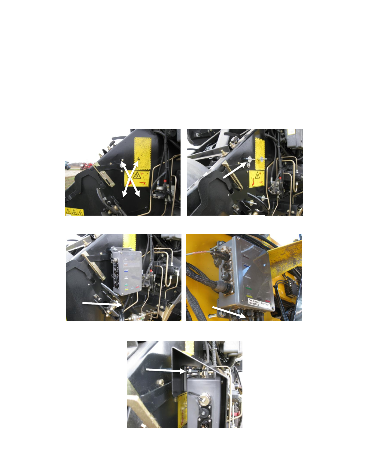
Connect the Power / Communication harness (006-6650TM(E)) to
the bottom of the receiver.
To operate the applicator, plug the iPad cord into the communication
port indicated by:
iPad Integration Control Light Signals
Green Slow Blink –Power supplied to the applicator system and the unit is going through its startup process.
This will take approximately 25-35 seconds.
Green Double Blink –Indicating the iPad module recognizes the iPad but the app is not open or connected.
Green Solid Light –Module is connected to the app and is ready to operate.
*Recommended to use the USB cable included with the applicator kit (006-6672USBC)
Bluetooth Receiver Lights
Pre-2020 applcaitors equipped with Bluetooth receivers (030-6672B)
are now equipped with lights to indicate both power and Hay App
connection on the Apple iPad. Clean light regularly
Blinking Lights –System is waiting for the processor to connect, which
could take up to 35 seconds.
Red Light –The Bluetooth receiver has power
Green Light –The Bluetooth receiver is connected to the Hay App.
**600 Series Applicators with serial number before DCP27000 will require the DCP to be sent to Harvest
Tec for a required update in order to use the iPad Integration Module (030-6672C).
Hay App version must be at least 2.7.1 (or higher) to operate with the iPad Integration Module
*Made for Apple iPad badge
Use of the Made for Apple iPad badge means that an accessory has been designed to connect specifically to
the Apple product(s) identified in the badge and has been certified by the developer to meet Apple
performance standards. Apple is not responsible for the operation of this device or its compliance with safety
and regulatory standards.
Please note that the use of this accessory with an Apple product may affect wireless performance.

8
Connecting Star Wheels to the DCP
600BB
Locate the moisture harness 006-7303HL. Remove the pan head
screws on each star wheel and remove the star wheel cover.
Loosen the black grommet.
Insert the eye loop of the wire into the star wheel block through the
grommet and install on the end of the swivel. Leave a loop in the
wire to allow the star wheel cover space to be reinstalled.
Tighten the swivel nut, followed by the grommet, and finally install
and tighten the four screws. Once both wheels are complete, route
the harness towards the DCP and secure loose wires with cable ties
after the star wheels are installed on the baler in the next step.
600BBHD
Locate the moisture harness 006-7303HX. Remove the pan head screws on each star wheel and remove the
star wheel cover. Loosen the black grommet.
Insert the eye loop of the wire into the star wheel block through the grommet and install on the end of the
swivel. Leave a loop in the wire to allow the star wheel cover space to be reinstalled.
Tighten the swivel nut, followed by the grommet, and finally install and tighten the four screws. Once both
wheels are complete, route the harness towards the DCP and secure loose wires with cable ties after the star
wheels are installed on the baler in the next step.
030-4641
Star Wheel Cover
Grommet
Grommet
Star Wheel Cover
030-4641U

9
Installation of Star Wheel Moisture Sensors –600BB
1. Locate the two star wheel moisture sensors (030-4641) and twine
diverters (001-4644 & 001-4645).
2. Directly behind the knotters, locate the four predrilled holes per side
shown at the arrows. This location is also beneath the lift points on
top of the baler (Figure 1).
3. Install the eight (four per side) 5/16” X 3” Allen head cap screws.
Make sure the Allen heads are in the bale chamber. Secure using 5/16” hex nuts (Figure 2).
4. Install the star wheels below the lift points on the baler.
5. Install the twine diverters over the star wheel sensor. The twine diverter with two extra holes will be
installed on the right star wheel when looking from the rear of the baler toward the tractor.
6. Secure the star wheels and twine diverters with four M8 hex nuts, lock washers, and two flat washers
(Figure 2).
Installation Bale Rate Harness –600BB
The bale rate sensors will be factory installed on the right side twine guard in the correct position. The sensor
with the longer sensor wire will say “FRONT” which indicates it should be placed in the front sensor hole. The
sensor wire with the shorter wire will say “BACK.”
The tip of the sensor should be placed no more than 1/4”(7mm) away from the star wheel teeth and no less
than 1/8” (3mm) from the star wheel teeth. Each sensor will have an LED light located on the sensor by the
diverter. Once the unit is powered up spin the wheel and make sure that both led lights turn on and off. If they
don’t turn on and off, adjustments may need to be made.
Once the star wheel connection is complete, run the harness along the left side baler frame to the Dual
Channel Processor (DCP). The Dual Channel Processor is located next to the flywheel brake.
Figure 1
Figure 2

10
Installation of Star Wheel Moisture Sensors –600BBHD
1. Locate the two star wheel moisture sensors (030-4641U) and star wheel reinforcement
brackets (001-4644BBHD) show on the right and parts bag A.
2. The two pre-drilled mounting holes for the star wheels are located past the knotters on the
side of the top support bar running the length of the bale chute (Figure 1).
3. Position the star wheel mounting holes and mark the width of the star wheel 3” (88mm). As
well as the depth of the star wheel of 2” (50mm). This piece will need to be removed from
the baler bracket in order for star wheel to fit flush with baler bracket (Figure 2).
4. Position the left side reinforcement bracket (001-4644BHD) around the star wheel. This will be labeled ‘Left
Side of Baler, This Side Up’. Shown mounted in Figure 3. Repeat mounting the star wheel and installation
of the reinforcement bracket on the right side of baler.
5. Locate the end of baler sensor bracket (001-4644SS) and the two bale rate sensors
(006-7303S). The sensors will be pre-mounted to the bracket. Mount the bracket
and sensors as shown in Figure 4. Sensors only mount on the left side of baler.
Figure 3
Figure 4
001-4644BBHD
Figure 2
Figure 1
001-4644SS

11
Installation of Bale Rate Harness –600BBHD
On the moisture harness 006-7303HX (connected to star wheel) locate the wire that says “FRONT” which
indicates it should be connected to the front sensor. Connect the wire that says “BACK” to the other sensor.
The tip of the sensor should be placed no more than 1/4”(7mm) away from the star wheel teeth and no less
than 1/8” (3mm) from the star wheel teeth. Each sensor will have an LED light located on the sensor by the
diverter. Once the unit is powered up spin the wheel and make sure that both led lights turn on and off. If they
don’t turn on and off, adjustments may need to be made.
Once the connection is complete, run the harness along the left side baler frame to the Dual Channel
Processor (DCP). The Dual Channel Processor is located next to the flywheel brake.
Installation of End of Bale Sensor –600BB
The end of bale sensor determines the position of the needles on the baler. When the needles cycle the
sensor communicates this information to the Dual Channel Processor. This information is used for job records
and will be used by the optional Bale Identification system.
Mount the end of bale sensor bracket (001-4648) as shown (above) on the ladder side of the baler (and same
side as the main controller). Mark and drill two 3/8” (10mm) holes and attach the bracket using two 5/16” x 1”
self-tapping screws, and 5/16” flange nuts. Keep the sensor 1/4" (7mm) from the needle and tighten both nuts.
New BB Balers have been installing the End of Bale Sensor in the second position and trimming off the excess
steel. Run the sensor cable (006-7400) and extension (006-7400BBEXT) up to the Dual Channel Processor
(DCP) down the ladder side of the baler and secure it properly out of the way of any moving parts and
hydraulics.
Installation of End of Bale Sensor –600BBHD
There is not an end of baler sensor included with the 600BBHD system. The moisture unit will use the baler
End of Bale sensor installed on the baler by retrieving the signal through the ISOBUS connection. Refer to the
operation manual for setup details.
A
B
C
2-7/9”
(75mm)
4-3/8”
(10.5cm)
5/8”
(16mm)
New Big Balers utilize the
second position for the End of
Bale Sensor.

12
Wiring Diagram
A. The Baler Power/Communication Harness (006-6650LS(E)) will attach to the open port of the Tractor
Harness (006-6650TM(E)) and run back to the Dual Channel Processor (006-6671LS(E)).
B. Connect the large plug of the Baler Power/Communication Harness (006-6650LS) to the bottom (shorter
side) of the DCP. Attach the Baler Interface Harness (006-6650VA) in between the short whip cable
hardwired to the DCP and the Power/Communication Harness (006-6650LS(E)).
C. Make sure Active Terminator removed from the top of the baler processor is attached to the Baler Interface
Harness (006-6650VA).
D. Attach moisture and bale rate harness (006-7303HL(E)) and also end of bale harness (006-7400BBEXT) to
the DCP (006-6671LS). Model 600BBHD will use harness 006-7303HX.
E. Connect Keyed Power Extension harness (006-5650K) to a keyed power source.
F. Connect the iPad Integration Control (030-6672C) to the Communication Harness (006-6650TM).
G. Note: The Optional Port and the Data Transfer Port are not used in this application.
Keyed Power Extension
006-5650K
Dual Channel
Processor (DCP)
006-6671LS
Moisture/Bale Rate Harness
006-7303HL (600BB)
or
006-7303HX (600BBHD)
Proximity Sensor
006-7303S
Star Wheel Assembly
006-4641 (600BB)
or
006-4641U (600BBHD)
End of Bale Sensor
006-7400
Optional Port
Terminating Connector
006-5650Z
Active Terminator
from Baler Harness
Baler Interface Harness
006-6650VA
iPad Integration Control
030-6672C
Orange Wire to
Keyed Power
Power/Comm Harness on Baler
006-6650LS(E)
Power/Comm Harness on Tractor
006-6650TM(E)
Data
Transfer
Baler
Connection
BB Extension for Bale Sensor
006-7400BBEXT
*Note: (E) indication is used
for International Dealers

13
Pin Outs
Power/Comm Harness 006-6650TM(E) at Hitch
Pin 1 Red +12V Power to TSD
Pin 2 Red +12V Power to DCP
Pin 3 Orange Keyed Power
Pin 4 Gray Shield
Pin 5 Green HT Can Low
Pin 6 Yellow HT Can Hi
Pin 7 Orange Can1 Hi
Pin 8 Black Ground from TSD
Pin 9 Black Ground from DCP
Pin 10 Blue Can1 Low
Power/Comm Harness 006-6650LS(E) at Hitch
Pin 1 Red +12V Power to TSD
Pin 2 Red +12V Power to DCP
Pin 3 Orange Keyed Power
Pin 4 Gray Shield
Pin 5 Green HT Can Low
Pin 6 Yellow HT Can Hi
Pin 7 Orange Can1 Hi
Pin 8 Black Ground from TSD
Pin 9 Black Ground from DCP
Pin 10 Blue Can1 Low
iPad Integration Control / BLE on Harness 006-6650TM(E)
Pin 1 Red +12V Power from DCP
Pin 2 Black Ground from TSD
Pin 3 Yellow HT Can Low
Pin 4 Gray Shield
Pin 5 Green HT Can Hi
Pin 6 Orange Can1 Hi
Pin 7 Blue Can1 Low
006-6650VA to DCP Whip
Pin 1 Red Can Power
Pin 2 Black Can Ground
Pin 3 Yellow HT Can Hi
Pin 4 Gray Shield
Pin 5 Green HT Can Low
Pin 6 Orange Can1 Hi
Pin 7 Blue Can1 Low

14
Pin Outs (continued)
006-6650VA to 006-6650LS(E)
Pin 1 Red Can Power
Pin 2 Black Can Ground
Pin 3 Yellow HT Can Hi
Pin 4 Gray Shield
Pin 5 Green HT Can Low
Pin 6 N/A
Pin 7 N/A
006-6650VA Harness to Baler Plug
Pin A N/A
Pin B Red TBC Power
Pin C N/A
Pin D Gray TBC Ground
Pin E Orange Can1 Hi
Pin F Blue Can1 Low
Main Power Connector on DCP
Pin 1 Red +12V Power from tractor
Pin 2 Black Ground from tractor
Pin 3 Orange Keyed power
Star Wheel and Bale Rate Sensor Connector on DCP
Pin 1 Blue +12V Power
Pin 2 Orange Ground
Pin 3 Black Signal for sensor 1
Pin 4 White Signal for sensor 2
Pin 5 N/A
Pin 6 N/A
Pin 7 N/A
Pin 8 Violet Star wheel input 1
Pin 9 Brown Star wheel input 2
End of Bale Sensor on DCP
Pin 1 Brown Sensor Power
Pin 2 Blue Sensor Ground
Pin 3 N/A
Pin 4 Black Signal from Sensor
D
F
A
F

15
Troubleshooting
PROBLEM
POSSIBLE CAUSE
SOLUTION
Moisture reading errors (high or low)
1. Wire disconnected or bad
connection between star wheels
and DCP
1. Reconnect wire.
2. Low power supply to DCP
2. Check voltage at box. (Min of 12
volts required.) See Diagnostics
section of manual.
3. Dry hay lower than 8%
moisture or wet hay over 75%.
3. System reads 8-70% moisture.
4. Ground contact with one or
both star wheels and baler
mounted processor.
4. Reconnect.
5. Short in wire between star
wheels and DCP.
5. Replace wire.
6. Check hay with hand tester
to verify.
6. Contact Harvest Tec if conditions
persist.
Moisture readings erratic.
1. Test bales with hand tester
to verify that DCP has more
variation than hand tester.
2. Check all wiring connections
for corrosion or poor contact.
2. Apply dielectric grease to all
connections.
3. Check power supply at
tractor. Voltage should be
constant between 12 and 14
volts.
3. Install voltage surge protection on
tractors alternator.
Terminal reads under or over power.
1. Verify with multi-meter actual
voltage. Voltage range should
be between 12-14 volts.
1. Clean connections and make sure
applicator is hooked to battery. See
Diagnostics section of manual.
Bale rate displays zero.
1. Bale rate sensors are
reversed.
2. Short in cable.
3. Damaged sensor.
4. Sensor too far from
starwheel.
1. Switch the sensors next to the
star wheel.
2. Replace cable.
3. Replace sensor.
4. Adjust gap between prox sensor
and star wheel so it is 1/8-1/4” away.
Bluetooth Receiver lights will not
illuminate
1. Bluetooth receiver not
connected
2. Harness disconnected
3. Low power
1. Check connections and voltage.
Minimum 12.5V needed.
Blinking Lights –System is waiting for the processor to connect, which
could take up to 35 seconds.
Red Light –The Bluetooth receiver has power
Green Light –When the proper active connection is selected in the Hay
App menu, the green light will indicate connection with the iPad.

16
Parts Breakdown
Controls and Harnesses
Ref
Description
Part Number
Qty
1
DCP Baler ISO/VT Harness
006-6650VA
1
2
EOB Extension for CNH BB Series
006-7400BBEXT
1
3
Key Switch Wire
006-5650K
1
4
End of Bale Sensor 600 Series
006-7400
1
5
End of Bale Sensor Bracket
001-4648
1
6
Terminating Connector 600 Series w/green cap
006-5650Z
1
7
DCP Shield/Cover
001-5650X
1
8
DCP Main Control LS 600 AUTO
006-6671LS
1
9
DCP Baler Harness 15 FT
006-6650LS(E)
1
10
DCP Tractor Harness
006-6650TM(E)
1
11
Dust Plugs
006-5651PLUGS
1
12
iPad Integration Control
030-6672C
1
NP
USB Cord
006-6672USBC
1
NP
End of Bale Sensor Extension (10’)
006-7400EXT
1
4
7
8
9
10
11
1
5
6
2
3
12
*Note: (E) indication is used
for International Dealers

17
600BB Star Wheels
600BBHD Star Wheels
Bale Rate Sensors
Ref
Description
Part#
Qty
1
Star wheel sensor
030-4641C
1
2
Snap ring (per side)
006-4641K
2
3
Washer (per side)
w/006-4641K
2
4
Dust seal (per side)
w/006-4641K
2
5
Star wheel block
006-4641A
1
6
Wiring grommet
008-0821A
1
7
Plug fitting
003-F38
2
8
Swivel insert
w/ Ref # 1
2
9
Electronic swivel
006-4642A
2
10
Block cover
006-4641B
2
11
Twine guard-left
001-4645
1
NP
Twine guard-right (prox)
001-4644
1
Star wheel Assembly
030-4641
(Ref 1-11)
Ref
Description
Part#
Qty
1
Univ Star Wheel
006-4641S
1
2
Dust Seal
006-4641DSL
2
3
Univ Star Block
006-4641Q
1
4
3/8” NPT Cable Grip
008-0821A
1
5
3/8” NPT Plug
003-F38
1
6
Thrust Washer
006-4641TA
2
7
Thrust Bearing
006-4641TB
1
8
Swivel Insert
006-4642B
1
9
3/4" Short Nut
006-4641U
1
10
Rotary Swivel
006-4642A
1
11
Cover Gasket
006-4641RG
1
12
Univ Block Cover
006-4641R
1
NP
Prox Sensor Holder
006-4644SS
1
NP
SW Reinforcement
001-4644BBHD
2
Star Wheel Assembly
(Ref 1-12)
030-4641U
Ref
Description
Part Number
Qty
13
Moisture & Bale Rate Harness
006-7303 HL(E)
2
14
Bale Rate Sensor
006-7303S
1
NP
Moisture & Bale Rate Harness
(600BBHD)
006-7303HX
1
3
4
4
8
1
2
5
7
3
2
9
10
6
*Note: (E) indication is used
for International Dealers
4
3
2
5
2
6
7
8
11
12
9
10
1
13
14

18
Optional iPad Display Kit (030-4670DK)
Ref
Description
Part #
Qty
Ref
Description
Part #
Qty
1
Suction cup mount
001-2012SCM
1
7
iPad Mini Charger 12V
001-2012P
1
2
Ram mount
001-2012H
1
8
iPad Mini 4 case
001-2012C4
1
3
iPad Mini®spring load
cradle (Mini 4)
001-2012SLC
1
9
iPad Mini 4
006-4670IP
1
4
16 gauge power wire
006-4723P
1
NP
4 amp fuse
Hardware
1
5
Female spade connector
Hardware
2
6
Eye loop connector
Hardware
2
Mounting Kit Assembly
030-4670DK
(Includes All Parts)
Installation Instructions
1. Identify 12V power source for wires to connect.
a. Eye loops included if wiring directly to the battery is desired.
b. Test for key power source if preferred to have power to the USB shut off with the key.
2. Once power source is identified, cut wires to desired length.
3. Crimp the two supplied quick connectors onto the white and black wire.
4. Remove the round locking plastic nut from USB plug before connecting the wires. Black (+) White (-).
5. The wires will then be hooked to the designated terminals on the bottom of the USB plug
6. Drill a 1 1/8” hole in the preferred mounting location. Be sure to clean any sharp edges after drilling.
7. Feed the wires through the mounting hole.
8. If using the round plastic nut to secure plug in place, slide the nut back over the wiring before connecting
the wires to powered source.
9. Connect the wires to the identified power source if easier to do so before tightening the plug into place.
10. Tighten plug using either the round plastic nut or mounting plate and two screws, both options supplied.
11. Once connected, hook a USB charging cord into the plug and connect a mobile device/tablet to ensure the
plug is operating as you wish (key power working properly if necessary).
NOTE: This plug is not designed to charge two iPads. System damage could occur if this is
attempted. System will charge a mobile phone and iPad simultaneously without problem.
*iPad mini is a trademark of Apple Inc., registered in the U.S. and other countries.
7
1
2
3
4
5
8
6
9

19
Harvest Tec Inc. Warranty and Liability Agreement
Harvest Tec, Inc. will repair or replace components that are found to be defective within 12 months from the
date of manufacture. Under no circumstances does this warranty cover any components which in the opinion
of Harvest Tec, Inc. have been subjected to negligent use, misuse, alteration, accident, or if repairs have been
made with parts other than those manufactured and obtainable from Harvest Tec, Inc.
Our obligation under this warranty is limited to repairing or replacing free of charge to the original purchaser
any part that in our judgment shows evidence of defective or improper workmanship, provided the part is
returned to Harvest Tec, Inc. within 30 days of the failure. If it is determined that a non-Harvest Tec branded
hay preservative has been used inside the Harvest Tec applicator system where the failure occurred, then
Harvest Tec reserves the right to deny the warranty request at their discretion. Parts must be returned through
the selling dealer and distributor, transportation charges prepaid.
This warranty shall not be interpreted to render Harvest Tec, Inc. liable for injury or damages of any kind,
direct, consequential, or contingent, to persons or property. Furthermore, this warranty does not extend to loss
of crop, losses caused by delays or any expense prospective profits or for any other reason. Harvest Tec, Inc.
shall not be liable for any recovery greater in amount than the cost or repair of defects in workmanship.
There are no warranties, either expressed or implied, of merchantability or fitness for particular purpose
intended or fitness for any other reason.
This warranty cannot guarantee that existing conditions beyond the control of Harvest Tec, Inc. will not affect
our ability to obtain materials or manufacture necessary replacement parts.
Harvest Tec, Inc. reserves the right to make design changes, improve design, or change specifications, at any
time without any contingent obligation to purchasers of machines and parts previously sold.
Revised 4/17
Other manuals for 600BB
2
This manual suits for next models
1
Table of contents
Other Harvest TEC Tractor Accessories manuals
Popular Tractor Accessories manuals by other brands

BE Ag & Industrial
BE Ag & Industrial CAR-TM Series Operations & parts manual

Tiger
Tiger BENGAL 5085M Series Mounting and operating instructions

Toro
Toro 03667 installation instructions

Koyker
Koyker 545 owner's manual

Grouser Products
Grouser Products RAM LOADER 40260 manual

Mahindra
Mahindra AppliTrac manual