HARVEY Gyro Air G-1000 User manual


1
Index of Contents
1. Foreword..................................................................................................................................................2
2. Machine Description.............................................................................................................................3
2.1 Feature Identification.................................................................................................................... 3
2.2 Specification................................................................................................................................... 4
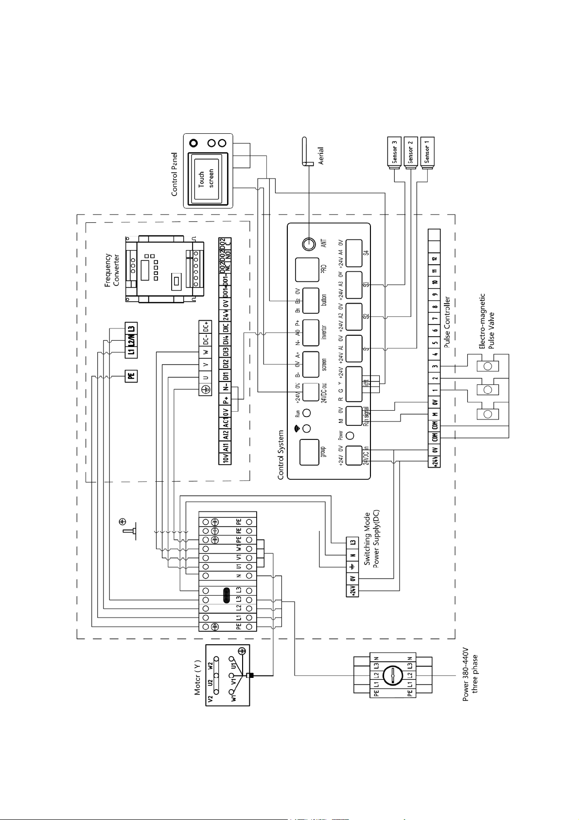
2.3 Electrical Power Requirement..................................................................................................... 5
3. Safety Regulations................................................................................................................................7
3.1 General Safety Instructions......................................................................................................... 7
3.2 Specific Safety Instructions for the Dust Processor.................................................................8
4. Installation of the Machine..................................................................................................................9
4.1 Transportation of Machine........................................................................................................... 9
4.2 Positioning the Machine............................................................................................................. 10
4.3 Assembly...................................................................................................................................... 10
4.3.1 Unpacking................................................................................................................................. 10
4.3.2 Removing the Pallet................................................................................................................ 10
4.3.3 Connection................................................................................................................................ 11
4.3.4 Power Supply............................................................................................................................11
4.3.5 Air Supply.................................................................................................................................. 12
5. Function and Operation.................................................................................................................... 13
5.1 Control Panel and Operation Instruction................................................................................. 13
5.1.1 Touch Screen Operation Instruction..................................................................................... 14
5.1.2 Supplementary Instruction for Dust Cleaning......................................................................18
5.2 Instructions for Remote Control................................................................................................ 18
5.3 Instructions for Synchronous Control.......................................................................................18
5.4 Pulse Controller Use and Control............................................................................................. 19
5.5 Use of Dust Bin............................................................................................................................20
5.6 Use of Dust Box.......................................................................................................................... 20
6. Maintenance......................................................................................................................................... 21
6.1 Cleaning Dust Bin....................................................................................................................... 21
6.2 Cleaning Dust Box...................................................................................................................... 21
6.3 Cleaning or Changing the Filters.............................................................................................. 21
6.4 Full Dust Bin or Pressure Drop Alarm......................................................................................22
6.5 Convertor Error and Alarm.........................................................................................................22

2
1. Foreword
This original instruction was developed as an integral part of this machine. It contains basic
information for qualified operating staff. It also contains all necessary information for the correct
and safe operation of this machine. These regulations, however, cannot cover all safety aspects.
The operator must peruse and make sense of this manual before starting to use the machine.
This manual should be put in a convenient place. If you lose this manual, please contact your
distributor for a new one.
We maintain the right to modify specifications, designs, operation and maintenance instructions
without advance notice.
We offer a two-year warranty based on the purchase date. Defective parts will be repaired or
replaced by Harvey at no charge.
We do not offer the warranty service for the following reasons:
Misuse
Lack of proper maintenance;
Not using genuine Harvey parts;
Consumable parts;
Force majeure, fire or explosion
Every machine we produce is fitted with a name plate with its serial number. The number
is also punched on the machine.
An exact description of the machine model and serial number will facilitate rapid and
effective replies from our after-sales service.

3
2. Machine Description
This product uses the Gyro Air dust processing technology, which effectively separates the dust
from the air flow before the filter. This machine has the following features:
Reduces filter clogging:
The Gyro Air technology efficiently separates 99.7% of the dust from the air flow BEFORE the
filter, providing the benefit of a lower capacity load on the filter and a longer filter life. The air flow
levels are also maintained for a longer time during normal operation.
Clean emission:
Emission concentration<0.05mg/m³, better than the CE standard of 0.1mg/m³. .
Intelligent control:
Real time monitoring of dust levels in the dust bin, filter clogging, convertor and motor status for
auto-dust cleaning; auto-start; remote-start; delayed dust cleaning.
Flow Cruise:
Intelligent speed control which maintains consistent air flow speed in the flow cruise mode.
Remarkable designs:
Heavy duty casters for easy positioning at the dust source; no need for specially designed
pipeline; easy connection; low cost for building dust collection system.
Easy maintenance:
Easily-to-change tool-less filters; exhaust air by internal circulation, low maintenance cost.;
Safety Standards:
CE (CONFORMITE EUROPEENNE).
This product is suitable for dry dust process, and can be used in the field of metal grinding, metal
cutting, wood machining, plastic machining, graphite machining, fiberglass machining, stone
cutting and surface polishing.
2.1 Feature Identification (Fig.1)
Fig.1
1. Cabinet 10. Filter
2. Flow Duct 11. Oil Water Separator
3. Separator 12. Disconnect switch
4. Inlet 13. Fan Motor
5. Dust bin 14. Power Cable
6. Operation Panel 15. Gas storage tank
7. Dust Box 16. Directional wheel
8. Swivel Wheel 17. Electrical box
9. Foots

4
2.2 Specification
Specification G-1000
Electrical Metric Imperial
Power Source 380-480V 50Hz 3-phase 380-480V 60Hz 3-phase
Main motor 3KW 4HP
Frequency Converter Siemens V20
Dimensions & Weights
Overall Dimension 1870x 940 x 1500 mm 73-3/5X37X59 in.
Packing Size 2140x1100x1730mm 84-1/4X43-1/4X68-1/8 in.
Net Weight/Gross Weight 445/545 Kg 980/1200 lbs
Performance
Inlet Size Φ160mm and Φ140mm 6“
Max. Air Flow 2700m³/h 1600CFM
Max. Static Pressure 6200Pa 25 inch water
Vacuum@22m/s 2200Pa @ Φ140mm /
Blower Speed 2400-4200rpm 2400-4200rpm
Impeller Size Φ360mm 14-1/8”
Filter Efficiency 99.95%@0.3μm 99.95%@0.3μm
Emission 0.05mg/m³ 0.05mg/m³
Filter Area 12.6 ㎡136SF
Number of Filters 3 3
Noise Level 61-72dB(A) 61-72dB(A)
Dustbin Capacity 150L 40Gal
Features
Smart Jet-Pulse Filter Cleaning Standard Standard
Dust Full Monitor Standard Standard
Filter Monitor Standard Standard
Flow Cruise Standard Standard
Wireless Remote Control Standard Standard
Wireless Synchronized Control Standard Standard
Optional Accessories
Remote Control(RC-800/1000) YES YES
Synchronized Control(SC-800/1000) YES YES
Y-Adapter(YA-150-2x100) NO YES
Dust Bag(DB-1000) YES YES

5
2.3 Electrical Power Requirement
Power requirement: AC380-480V 3-phase
Breaker Size: 20A
The machine needs no further electrical installation.
For the North American market, the equipment comes with a cable (4 cords).
For the European market, the machine is equipped with an industrial socket (5 cords).
The input power supply of the machine is 3-phase, AC380-480V. The steady-state AC power
supply is 0.9-1.1 times of the rated value.
2.3.1 Equipment grounding
This machine must be grounded. If it should malfunction or breakdown, grounding provides a
path of least resistance for the electric current to reduce the risk of electric shock. This appliance
is equipped with a cord having an equipment-grounding conductor and grounding plug. The plug
must be inserted into an appropriate outlet that is properly installed and grounded in accordance
with all local building codes and ordinances.
WARNING – Improper connection of the equipment-grounding conductor can result in a risk of
electric shock. Check with a qualified electrician or service person if you are in doubt as to
whether the outlet is properly grounded.
2.3.2 Cable Inspection and Extension
Before using, you need to check the cable to see if there is any damage. If any, it should be
immediately repaired or replaced.
Extension cables cause a voltage drop, which may damage electrical components and shorten
the motor life. Voltage drop increases as the extension cable size gets longer and the cable size
gets smaller.
Minimum Gauge Size ........................... 2.5mm2(14 AWG)
Maximum Length (Shorter is Better).......15m (50 ft).

6
2.3.3 Electrical diagram(Fig.2)
Fig.2

7
3. Safety Regulations
3.1 General Safety Instructions
1. Read and understand the owner’s manual and labels affixed to the machine. Learn its
application and limitations as well as its specific potential hazards.
2. The power supply socket or terminals need reliable grounding.
3. Keep the machine in good working order, properly adjusted and aligned. Cluttered areas and
benches may invite accidents. Make sure the floor is clean and not slippery due to wax and
sawdust build-up.
4. WARNING! – To reduce the risk of electric shock:
Do not expose the machine to water or moisture.
Operators shall be adequately instructed on the use of these machines.
5. CAUTION! – This machine is for indoor use only.
This machine shall be stored indoors only.
6. Do not use this machine within the designated safety areas of flammable liquid storage or in
areas where there may be volatile gasses. Keep the work area clean, dry, and well-lit.
7. Keep children away from this machine.
8. Don’t force the machine or the attachment to do a job for which it was not designed.
9. Do not wear loose clothing, gloves, neckties or jewelry (rings, watch) because they could get
caught in moving parts. Non-slip footwear is recommended. Wear protective hair covering to
contain long hair. Roll up long sleeves above the elbows.
10. Do not use this machine if you are tired, your attention is wandering or you are distracted.
11. If the work operation appears to be excessively noisy, it’s advisable to wear ear protection.
12. Always wear safety glasses or a face shield when operating or observing machinery to
reduce the risk of eye injury or blindness from flying particles. Everyday eyeglasses are not
approved safety glasses.
13. WARNING! – To reduce the risk of electric shock:
Always unplug the machine during servicing.
14. WARNING! – To reduce the risk of injury from moving parts:
Always unplug the machine before servicing.
15. Make sure the power switch is in the “OFF” position before plugging it into an electrical outlet.
16. When turning the power ‘’OFF’’, do not leave the machine unattended until it comes to a
complete stop.
17. Regularly inspect the machine for damaged parts, loose bolts or any other conditions that
may effect safe operation. Always repair or replace damaged parts before operating machine.
18. Keep the machine clean. This will enable you to easily see any damage that may have
occurred. If need be, clean the machine with a damp soapy cloth. Do not use any solvents or
cleaners as these may cause damage to any plastic parts or to the electrical components.

8
3.2 Specific Safety Instructions for Dust Processor
1. CLEAN ENVIRONMENT
Once you are ready to commence work, remove any tools, objects or items that could
inadvertently get ‘sucked up’ by the machine and place them safely out of the way.
2. INTENDED USE
Do not use this machine as a vacuum cleaner. Avoid stones, nails, etc., as it may produce a
spark and cause a fire or an explosion. This machine is not suitable for picking up hazardous
dust.
3. FIRE SUPPERSSION
Only operate the dust collector in locations that contain a fire suppression system or have a fire
extinguisher nearby.
4. REGULAR CLEANING
Regularly check/empty the collection bags to avoid the buildup of fine dust that can increase the
risk of fire. Make sure to regularly clean the surrounding area where the machine is operated
--excessive dust buildup on overhead lights, heaters, electrical panes, or other heat sources will
increase the risk of fire.
5. STATIC ELECTRICITY
Plastic dust lines generate high amounts of static electricity as dust chips pass through them.
Although rare, sparks caused by static electricity can cause explosions or fire. To reduce this risk,
make sure all dust lines are thoroughly grounded by using a grounding wire.
6. HAZARDOUS DUST
Dust created while using machinery may cause cancer, birth defects, or long-term respiratory
damage. Be aware of dust hazards associated with each workpiece material, and always wear a
NIOSH-approved respirator to reduce your risk.
7. DUST ALLERGIES
Dust from certain woods may cause an allergic reaction in people and animals. Make sure you
know what type of wood dust you will be exposed to in case there is a possibility of an allergic
reaction.
8. IMPELLER HAZARDS
Do not place your hands or tools near the open inlet during operation for any reason. The
powerful suction could easily cause accidental contact with the impeller which will cause serious
personal injury or damage to the machine. Always keep small animals and children away from
open dust collection inlets.

9
4. Installation of the machine
This machine needs little-to-no assembly. It can almost be used directly out of the box.
4.1 Transportation of machine
4.1.1 Transportation and storage
The machine should be transported and stored in -25~55°C (-77~131°F) ambient temperature.
Take care not to allow the machine to be exposed to rain or damage to the packing during
transportation and storage.
●While transporting or handling the machine, be careful and let the activity be done by
qualified personnel especially trained for this kind of activity!
●While the machine is being loaded or unloaded, make sure that no person is too close to
be subject to injury.
●Select the proper transportation device according to the weight of the machine.
●Make sure the lifting capacity of the transportation device is capable for the weight of the
machine.
The machine is very heavy therefore serious personal injury can happen if safe moving
methods are not followed! To be safe, you will need assistance and power equipment
when moving the shipping crate and removing the machine from the pallet!
4.1.2 Transportation before unpacking
As standard, the machine is packed in a robust wooden box.
Fig. 3 shows the method which can be used to transport the machine..
Fig.3
4.1.3 Confirmation after unpacking
When opening the packing box, please pay attention to the following items. If you have any
questions, please contact your after sales department.
1) Has the machine been damaged in transportation?
2) All accessories and documents are included with the machine.
3) The product is consistent with the contract.
4) The specifications on the machine label are consistent with the contract.
4.1.4 Transportation after unpacking
When transporting the machine with a forklift, first find the center of gravity of the machine,
insert the fork below the machine and then lift carefully.

10
4.2 Positioning the machine
Fig.4
The machine should be placed at least 50cm (18 inches) away from the wall to ensure that the
motor heat dissipation is adequate.
4.3 Assembly
4.3.1 Unpacking
Open shipping container and check for shipping damage. Report any damage immediately to
your distributor and shipping agent.
4.3.2 Removing the Pallet
AsshowninFig.5,themachineismountedonapallet by four (4) L shaped brackets. Remove
the 4 brackets by loosening the bolts. Lift the machine by the forklift and remove the pallet
The side of the machine where the motor is mounted is heavier therefore its important to
keep the machine balanced while lifting it to avoid serious injury.
To avoid serious injury, engage the two rubber feet once the machine is in its final position
to prevent unexpected movement (See Fig 6).
Fig.5 Fig. 6

11
4.3.3 Connection
Use flexible hose or solid pipe to connect the inlet with the dust source.
Plastic pipe, such as Polypropylene or Polyvinyl Chloride, can be used as long as it’s been
determined and confirmed that the dust is not an explosion hazard.
NOTE: This machine does not contain dust collection hose(s) due to the dust source
differences.
4.3.4 Power Supply
Fig.7 Fig.7-1
Wire the machine as indicated on the name plate. Refer to the electricity diagram as shown in Fig.
2 if needed.
For the North American market, the equipment comes with a cable (4 cords). (Not shown)
For the European market, the machine is equipped with a industrial socket (5 cords). (See Fig.7)
Grounding
As shown in Fig. 7, there is a grounding screw on the back side of the machine. This machine
should be connected to a permanent, grounded metal wiring system through this screw.
Check motor rotation:
(As shown in Fig. 7-1). If not rotating in the proper manner, any two power supply cables L1, L2
and L3 should be switched. This operation should be completed by a professional electrician.
Electrical connections must be made by a qualified electrician in compliance with all
relevant building codes and ordinances.
Make sure the switch is in the “OFF” position before connecting to the power supply to
avoid an unexpected start.
This machine must be properly grounded to help prevent electrical shock and possible
fatal injury.
Repair or replace a damaged or worn cord immediately.
Using an extension or undersized cords will cause a drop in the line voltage and may
result in loss of power and possible overheating.

12
4.3.5 Air Supply (compressed air)
Make sure the switch is in the “OFF” position before connecting to the compressor to
avoid an unexpected start.
Air pressure requirement should be at least 0.8MPa (115psi).
As shown in Fig. 8, follow the instruction below:
Inspect the oil water separator pressure valve. If it is not shown at 0.6MPa, please adjust it to
0.6MPa.
Close the drain valve under the gas container. (The handle is in the horizontal position).
Mount an 8mm air hose to the position pointed in Fig. 8.
Fig.8
Congratulations!
You have completed assembly of this machine.

13
5. Function and Operation.
5.1 Control Panel and Operation Instruction
This machine has a built-in Intelligent Control System, providing live monitoring and functional
control of the machine.
Fig.9
A: Three-color indicator:
Red: power on and the machine is not running.
Yellow: dust bin is full or filter clog alarm.
Green: the machine is running in normal status.
B: Start Button: Start the machine.
C: Stop Button: Stop the machine.
D: Touch Screen:
Shows the running information and setting information of the machine.
Sets up the mode and parameter of the machine.

14
5.1.1 Touch Screen Operation Instruction:
When the power is connected, the touch screen will light up and the main interface will display (as
shown in Fig 10).
Fig.10 Fig.10-1
The touch screen has four sections:
E: Running status display area.
F: Alarm information display.
The countdown of delayed stop.
G: Operation and control area.
H: Parameter set up area.
-------------------------------------------------------------------------------------------------------------------------------
E: Instructions of running status display (Fig.10-1)
E1: Shows motor running speed or motor running power
Shows the motor running speed (rpm) while in speed mode.
Shows the motor running power (W) while in cruise mode.
E2: Shows the filter status
P1 is the pressure front of the filter (Pa)
P2 is the pressure back of the filter (Pa)
The green number on the right side of the pressure scale is the set pressure difference threshold
value (pa); the red pointer of pressure scale indicates the current front and back pressure
difference of filter.
E3: Shows dust bin status
Dust bin full; Dust bin not full.
E5: Shows the current start/stop mode
Manual mode; Linkage mode.
E5: Shows the current running mode
Speed adjustment mode; Cruise mode.

15
F: Instructions of alarm information display (Fig.10-2)
Fig.10-2 Fig.10-3
There is no display in normal status.
F1: Shows the communication failure between touch screen and main controller (in electric box).
F2: Shows the communication failure between main controller and convertor (in electric box).
Note:When the machine is not functional, the error code or alarm code will display in F1, which
will show maximum 4 error codes and 1 alarm code. The newest error code shows on the left side;
the others show the historical non-eliminated error codes. While the machine is delayed to stop,
the countdown of delayed stop will show here (A unit is a second).
G: Instructions of operation and control (Fig.10-3)
G1: Delayed stop
Clicking on this button, the machine will be delayed to stop general cleaning of the indoor air
near the workspace in a set time.
For setting the delayed stop, please see “H4: set up of delayed stop”.
The default time of delayed stop is 5 minutes.
G2: Dust cleaning of filter
Clicking on this button, the machine will clean dust for a period of time.
Note: Under the mode of “off-line dust cleaning”, this button will not work while the machine is
running(see H5:dust cleaning mode and parameters set up).
G3: Re-link
There is no display in normal status.
When the start/stop mode of the machine is set up to the linkage mode, the manual start/stop
operation (including the remote control) will change the mode into manual mode on its own. Only
the manual start/stop operation is permitted at this time. The G3 button will display in this area.
By clicking on the G3 button, it will once again be re-linked.

16
H: Instructions of parameter set up (Fig.10-4)
Fig.10-4
H1: Back button
Press this button back to home page (main interface).
H2: Start/stop set up
There are two start/stop modes of the machine:
1) Manual start /stop mode
2) Intelligent linkage start/stop mode (The dust source equipment should be connected to the
Synchronous Control. See operation instructions of the Synchronous Control).
Select and confirm the desired “start/stop” mode by Clicking on button “start/stop” (Fig.10-5)
Fig.10-5 Fig10-6
H3: Running mode set up
The machine can run in speed adjustment mode or flow cruise mode. Select the desired running
mode by clicking on the button “mode setup” (Fig.10-6).
NOTE: If selecting the speed adjustment mode, click on the data input area indicated by
the arrow to enter the motor speed. The selected range of speed is 2400-4200rpm. The
2400 rpm is factory set.
If selecting the cruise mode, click on the data input area indicated by the arrow to enter
the motor power. The selected range of power is 2000-3500W. The 2000W is factory set.
H4: Delayed stop set up
When dust collection is finished, the motor can be set up to delayed stop for general cleaning of
the air near the workspace. The delayed stop timer can be set up by the user.
Click on the “delayed stop” button to enter the set up interface (Fig.10-7). Then click on the data
input area indicated by the arrow to enter the desired time of delayed stop. The setting range of
delayed time is 1-180 minutes and the default time is 5 minutes.

17
Fig.10-7 Fig10-8
H5: Set up of the dust cleaning parameter and mode
Set up the dust cleaning parameter and select the dust cleaning mode by clicking on the “dust
cleaning set up” button (Fig.10-8).
Set up the dust cleaning parameter: (Fig.10-8)
1. Click on the input area of the filter pressure difference threshold value, to enter the set
pressure difference threshold parameter(recommended input range:
300-900),then click on the
OK button after entering the parameter. (The system default pressure threshold value is 600pa)
2. Click on the input area of the off-line time to enter a set time of off-line dust cleaning
(recommended input range: 5-90 ), then click on the OK button after entering the parameter.
(System default off-line dust cleaning time is 30 minutes.)
Note: The off-line dust cleaning time parameter is meaningful only when the dust cleaning
mode is set to off-line dust cleaning mode, otherwise there is no need to set up the
parameter.
Set up the dust cleaning mode: (Fig.10-8)
a) Dust cleaning by pressure difference:
This mode allows dust cleaning while the machine is running. If the pressure difference is higher
than the setting value, the dust cleaning system functions until the pressure difference is lower
than the setting value.
b) Off-line dust cleaning
Dust cleaning after stopping the machine with the power connected.
c) Sustained dust cleaning
Once the machine is connected to the power, dust cleaning works constantly (default mode).

18
5.1.2 Supplementary Instruction for Dust Cleaning
In addition to manual dust cleaning, dust cleaning by pressure difference, off-line dust cleaning
and sustained dust cleaning, the system also has the following dust cleaning functions:
When the machine is connected to power, it will clean the dust automatically for 5 minutes.
When the machine is stopped (with power connected), it will clean the dust automatically by
one period.
Note: While the machine is set to off-line dust cleaning, starting the machine will stop the
ongoing dust cleaning.
5.2 Instructions for Remote Control (Fig.11)
The Remote Control can be used to start and stop the dust processor. The remote control will
connect the main controller of the dust processor through WIFI. The effective control distance is
approximately 30 meters. When using the remote control, the operator does not need to aim the
remote control to the dust processor.
Fig. 11
For detailed operating instructions, please refer to the operation manual of the Remote Control.
5.3 Instructions for Synchronous Control (Fig.12)
The user can achieve the synchronous operation of the dust processors and the dust source
equipment by using Synchronized Control. After a simple installation and setup, the start and
stop of the dust processors will automatically associate the dust source equipment.
Fig. 12
For detailed operating instructions, please refer to the operation manual of the Synchronized
Control.

19
5.4 Pulse Controller Use and Control (Fig.13)
Regardless of the selection of dust cleaning methods, both the pulse interval and periodic interval
need to be set on the pulse controller.
The pulse dust cleaning is controlled by the pulse controller (Installed in the electrical box). The
operation buttons and wiring terminals are shown below:
Fig.13
Indicators area: each indicator shows the present status of the controller.
a. Power indicator:shows if it is connected to the power supply.
b. Running indicator: “Off” when setting the parameter, “on” when the setting is completed.
c. Other 4 indicators: “On” means setting the corresponding parameter.
Digital display: shows the setting parameters.
Function buttons: for choosing the setting functions. Pressing the button once will choose the
function for set up.
Set knob: set up the parameters.
Function and parameters set up list:
Function name Initial parameter Allowed range
Power on function 3 Pre-set at the factory
Number of pulses 2 Pre-set at the factory
Period cycle 300 seconds 60-600 seconds
Pulse period 10 seconds 10-20 seconds
Width of pulse 0.12 seconds 0.1-0.5 seconds
Parameter description:
Power on function: not applicable for this machine.
Number of pulses: the number of pulse magnetic valves equipped on the machine.
Period cycle: refers to the time between the pulse magnetic valves opening and closing (Cycle 1
and Cycle 2).
Pulse period: the time between each magnetic valve opening is the pulse period, in one cycle.
Width of pulse: the open time of the magnetic valves.
Other manuals for Gyro Air G-1000
1
This manual suits for next models
1
Table of contents
Popular Computer Hardware manuals by other brands

Unipulse
Unipulse f395 Operation manual

Kvaser
Kvaser USBcan II user guide

ekwb
ekwb EK-Quantum Vector RTX 3080/3090 D-RGB user guide

Sierra Wireless
Sierra Wireless MC5725V Hardware integration guide

Peavey
Peavey IDL 1000 user guide

YUNEX TRAFFIC
YUNEX TRAFFIC ST950SPlus+ Installation and commissioning manual