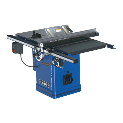
HARVEY HPS1600E User manual

W741
HPS-1600E
PANEL SAW WITH SCRIBE BLADE
INSTRUCTION & PARTS MANUAL
14-9-11

298003602

- 2 -
Declaration of Conformity
(Manufacturer’s Declaration)
We
:
Harvey Industries Co., Ltd.
East Gate, 1519 Shuanglong Street, Jiangning Development Zone, Nanjing, Jiangsu 211112, P.R. China
declare in sole responsibility that the equipment
Sliding Table Saw
Model: J-20, J-30, HPS-1600E, HPS-1300E
Serial Number: 110001R, 110002R, 110003R, 110003R
to which this declaration applies, complies with the following directives and/or standards:
2006/42/EC
2006/95/EC
2004/108/EC
2002/96/EC
EN 60204-1:2006+A1:2009
EN 1870-1:2007+A1:2009
This declaration is based on:
Third party testing, performed by TÜV Rheinland LGA Products GmbH xTillystraße 2 xD -
90431 Nürnberg, Germany, with identification number of Notify Body: 0197.
TÜV Rheinland Technical Report Nr.: 17703891 001
TÜV Rheinland Certificate Nr.: BM 50202970 0001
Notes:
This declaration becomes invalid, if technical or operational modifications are introduced
without the manufacturers consent.
Person responsible for keep the technical file:
Name, Surname:
Address:
Person responsible for making this declaration:
Name and Signature: HuaYi
Date and Place: 2011-08-05 NanJing
The title of signature:

- 3 -
Contents
1. Foreword
2. Warranty Information
3. Machine Description
3.1 Feature Identification
3.2 Intended Use
3.3 Dimensions and weights
3.4 Requirements of electrical power
3.5 Noise
3.5.1 Reference standards
3.5.2 Operating conditions
3.5.3 Testing results
3.6 Technical parameters
4. Safety Regulations
4.1 General Safety Instructions
4.2 Specific Safety Instructions for Sliding Table Saw
4.3 Residual risks
4.4 Safety equipment
4.5 Safety labels on the machine
4.6 Safety devices
5. Installation of the machine
5.1 Transportation of machines
5.1.1 Transportation and store
5.1.2 Transportation before unpacking
5.1.3 Confirmation after unpacking
5.1.4 Transportation after unpacking
5.2 Unpacking
5.3 Safety meausures before use/installation
5.4 Installation
5.4.1 Moving & Placing Base Unit
5.4.2 Installation of Sliding Table
5.4.3 Installation of crosscut table
5.4.4 Side Extension Table Installation
5.4.5 Rear Extension Table Installation
5.4.6 Installation of Rip Fence Scale Tubing and Guide Bar
5.4.7 Blade installation and changing
5.4.8 Blade Guard & Riving knife installation
5.4.9 Connecting the extraction system
5.4.10 Electrical installation
6. Adjustment
6.1 Sliding table
6.2 Main Table
6.3 Scoring blade
6.4 90 and 45 degree stops
6.5 Crosscut fence
6.6 Rip Fence
7. Operations
7.1 Electrical Operations

- 4 -
7.2 Safety precautions before operation
7.3 Crosscutting
7.4 Rip Cutting
7.5 Clamping shoe
7.6 Operation of handle
7.7 Working examples
8. Maintenance
8.1 Cleaning
8.2 Lubrication
8.3 Replacing belt
8.4 Air gap adjustment of brake
8.5 maintenance and repair of push block handles and push sticks
9 Trouble shouting guide
10 Parts list

- 5 -
1. Foreword
This manual was conceived at the manufacturer and is an indivisible part of the
deliveryenclosed with the machine. It contains basic information for qualified operating
staff and describes the surroundings and using ways of the machine for those it is
intented. It contains also all necessary information for a correct and safe operating.The
machine is equipped with various safety equipment protecting operator and machineas
well at usual technological using. These regulations, however, cannot sheet all
othersafety aspects. That is why operator must peruse and make sense of this manual
before starting of machine use. Installation and operation mistakes will be foreclosed
herewith.
Do not try to start the machine before having read all instructions manualdelivered
with the machine and understood every function and technique.
2. Warranty Information
Limited Warranty
One year
Proof of Purchase
Please keep your dated proof of purchase for warranty and servicing purposes.
Limited Tool Warranty
we makes every effort to ensure that this product meets high quality and durability
standards. we warrants to the original retail consumer a 1-year limited warranty as of the
date the product was purchased at retail and that each product is free from defects in
materials. Warranty does not apply to defects due directly or indirectly to misuse, abuse,
normal wear and tear, negligence or accidents, repairs done by an unauthorized service
center, alterations and lack of maintenance. we shall in no event be liable for death,
injuries to persons or property or for incidental, special or consequential damages arising
from the use of our products.
To take advantage of this limited warranty, return the product at your expense
together with your dated proof of purchase to us ,we will either repair or replace the
product if any part or parts covered under this warranty which examination proves to be
defective in workmanship or material during the warranty period.

- 6 -
3. Machine Description
3.1 Feature Identification
No. Description HPS1600E Remark
1. main base unit ●
2. swing arm
●
3. crosscut table
●
4. crosscut fence
●
5. sliding table ●(1600mm)
6. edge shoe plate
●
7. rear extension table ●
8. Blade guard with Riving Knife ●
9. main table
●
10. side extension table ●(50")
11. rip fence ●
12. Round guide bar ●(50")
13. Sliding table handle ●
14. support leg ●(3pcs)
15. connector plugs ●
16. on/off/ emergency stop button ●
17. Vertical adjustable hold down ●
18. Mini crosscut table & fence (optional) Not shown
19. Overhead (optional) Not shown

- 7 -
3.2 Intended Use
HPS1600E & HPS1300E Sliding table saw and the workpiece guide equipment supplied
with it are intended to be used exclusively for the following purposes:
● Laminated and unlaminated board materials (e.g. chipboard, coreboard, MDF board, ...)
● Solid wood
● Gypsum plasterboard
, Cardboard, Veneer with a suitable clamping device
● Dimensionally stable plastics (thermoset plastics, thermoplastics).Sawing these materials does
not normally involve any risks in respect of dust, chips, and thermal degradation products.
Tools:
● The chosen saw blade must be suitable both for the specific work cycle and for the specific
material.
● Only circular blades which are solid chrome vanadium (CV) or tungsten carbide tipped (TCT)
and have a diameter of 315mm , arbor size 30mm,as well as a maximum width of 20mm are
allowed for the main saw
● Blades with a diameter of 120mm,arbor size 20mm
are allowed for the scoring saw.
● Saw blades made of high-alloy high-speed steel (HSS) are not allowed to be used.
● Saw blades and their fixing devices shall conform to EN 847-1:2005。
Site of installation/use:
● The machine is not suitable for use outdoors, or in rooms that are subject to moisture or the risk of
explosions.
● The intended use of the machine involves connection to a suitably dimensioned extraction
system .
● Intended use also involves compliance with our specified operating, maintenance and repair
conditions and the safety information contained in the operating instructions.
● The sliding table saw may only be used, set up and maintained by persons who are familiar with
the machine and aware of the dangers.
● The pertinent accident prevention regulations as well as any other generally recognised technical
safety and industrial medicine rules must be observed.
● Repair work must be carried out by our own customer service or by an organization that we have
authorized. Only original spare parts are allowed to be used for this. we will assume no warranty
for any damage that is caused by using non-original spare parts.
Machine operator positions(Fig.1)
The sliding table is intended to be operated from the following positions:
●On the left of the sliding table at the front of the machine, seen in the
feed direction (main operator position).
●At the front cross-end of the machine on the right of the sliding table
when working with the rip fence
● Any person removing the workpieces must stand at the rear
cross-end of the machine behind the main table length extension (under
no circumstances in the sliding table traverse area).
Fig.1
The machine is prohibited to be used in a potentially explosive atmosphere!
- 8 -
3.3 Dimensions and weights
Machine
type
Sliding
table
lenth
Net/gross
weight of
machine
box(Kg)
Net/gross
weight of
sliding table
box(Kg)
Dimensions of
machine
box(DxWxHmm)
Dimensions of
sliding table
box(DxWxHmm)
HPS1600E 1600mm 430/490 130/160 1380x1120x1035 1900x420x250
3.4 Requirements of electrical power
List of the motor using & pre-wired voltage
Main Motor/scoring
motor(KW) Voltage(V) Freq.(Hz) Nominal current
A with scoring
blade Prewired Cords
4/0.55 400V 50 7.82/1.39 400V 3PH 5
The input power supply of the machine is 3/N/PE, AC400V. The steady-state AC power
supply is 0.9~1.1 times of the rated value.
•Frequency
0.99~1.01 times of rated frequency ( 50 Hz , continuous working)
0.98~1.02 times of rated frequency(50Hz, short period working)
•Harmonics
The sum of 2nd-5th distorted harmonic must not exceed 10% of RMS of voltage. An
additional 2% of RMS of line voltage is allowed to for the sum of 6th-30th harmonic.
•Unbalanced voltage
Neither Negative nor zero sequence components is allowed to exceed 2% of the positive
sequence component.
•Electrical protection
End user should provide protection device against overvoltage due to lightning and
short-circuited protection device at the power supply.
•Ingress Protection at the inlet of incoming power cable
The incoming method of incoming cable should ensure IP54 protection class when
finishing installation on the spot.

- 9 -
3.5 Noise
3.5.1 Reference standards
The measurements of noise emission were conducted according to the EN ISO 11202 for the
determination of sound pressure level at the operation positions. When the measured sound
pressure levels at the operation positions exceed 85dB(A), the measurements of sound power
levels were conducted according to EN ISO 3746.
3.5.2 Operating conditions
The operating conditions for noise measurement comply with AnnexA of ISO 7960:1995.
3.5.3 Testing results
NO LOAD LOAD
LWA 91.8 97
Position A 77.7 85.0
Position B 80.3 86.5LPA Position C 73.0 74.9
Associated uncertainty K = 4 dB
Note: Background noise of measurement surrounding is 65.0dB (A).
The figures quoted are emission levels and are not necessarily safe working levels. Whilst
there is a correlation between the emission and exposure levels, this cannot be used reliably to
determine whether or not further precautions are required. Factors that influence the actual level
of exposure of the workforce include the characteristics of the work room, the other sources of
noise etc. i.e. the number of machines and other adjacent processes. Also the permissible
exposure level can vary from country to country. This information, however, will enable the user of
the machine to make a better evaluation of the hazard and risk.”

- 10 -
3.6 Technical parameters
Models HPS1600E
Overall Size (DxWxH) 3630mmx4330mmx1095mm
Table Height 860mm
main Table Size 495mm x 800mm
Sliding Table Size 361mm x 1600mm
Machine Net Weight Approx. 560 kg
Overall
Dimensions
Machine foot print 715mm x 1030mm
Main Blade Diameter (Maximum) 250mm
Main Blade Arbor Size 30mm
Main Blade Arbor Speed 4500/min
Scoring Blade Diameter 120mm
Scoring Blade Arbor Diameter 20mm
Scoring Blade Arbor Speed 6500/min
Maximum Depth of Cut at 90° 75mm
Maximum Depth of Cut at 45° 52mm
Dado Width (Maximum) 20mm
Blade Tilt Right
Maximum Ripping Capacity 1270mm
Maximum Length of Cross Cut Fence 2580mm
Capacities
Maximum Cross Cutting Length 1600mm
Sliding Table T-6 Super Heavy Duty Extrusion
Machine Frame High Strength 4mm/6mm Steel Welding (Laser Cut)
Cross Fence Extruded T-6 Aluminum with fine anodization
Rails Chromed Plated Steel (40mm Dia)
Construction
Trunnions High Grade Cast Iron, Precisely Machined
Motor 400V/50Hz/3Ph/4kW 2850/min TEFC
Power Transfer Belt Drive
Blade Guard with 50mm dust port
100mm Main Dust Port
Adjustable Riving Knife
Micro Adjustable Rip Fence
Features
Ball Bearings: Sealed and Permanent Lubrication
Every machine we produce is fitted with a name plate with its serial number. The number is
also punched on the machine.
An exact description of the machine model and serial number will facilitate rapid and effective
replies from our after-sales service.
Position of nameplate: on the side of the main base unit.
It is prohibited to alter the information given on the nameplate!

- 11 -
4. Safety Regulations
4.1 General Safety Instructions
1. KNOW YOUR MACHINE.
Read and understand the owners manual and labels affixed to the machine. Learn its
application and limitations as well as its specific potential hazards;
2.GROUND THE MACHINE.
In the event of the electrical short, grounding reduces the risk of electrical short;
3. KEEP GUARDS IN PLACE.
Keep in good working order, properly adjusted and aligned;
4. REMOVE ADJUSTING KEYS AND WRENCHES.
Form habit of checking to see that keys and adjusting wrenches are removed from machine
before turning it on;
5. KEEP WORK AREA CLEAN.
Cluttered areas and benches invite accidents. Make sure the floor is clean and not slippery
due to wax and sawdust build-up;
6. AVOID DANGEROUS ENVIRONMENT.
Don’t use machines in damp or wet locations or expose them to rain. Keep work area well lit
and provide adequate surrounding work space;
7. KEEPCHILDREN AWAY.
All visitors should be kept a safe distance from work area;
8. MAKE WORKSHOP CHILD-PROOF.
With padlocks, master switches or by removing starter keys;
9. USE PROPER SPEED.
A machine will do a better and safer job when operated at the proper speed;
10. USE RIGHT MACHINE.

- 12 -
Don’t force the machine or the attachment to do a job for which it was not designed;
11. WEAR PROPER APPAREL.
Do not wear loose clothing, gloves, neckties or jewelry (rings, watch) because they could get
caught in moving parts. Non-slip footwear is recommended. Wear protective hair covering to
contain long hair. Roll up long sleeves above the elbows;
12. DON’T OVER REACH.
Keep proper footing and balance at all times;
13. MAINTAIN MACHINE WITH CARE.
Keep tools sharp and clean for best and safest performance. Follow instructions for
lubricating and changing accessories;
14. DISCONNECT MACHINES.
Before servicing, when changing accessories or attachments;
15. AVOID ACCIDENTAL STARTING.
Make sure the switch is in the ‘’OFF’ ’position before plugging in;
16. USE RECOMMENDED ACCESSORIES.
Consult the manual for recommended accessories. Follow the instructions that accompany
the accessories. The use of improper accessories may cause hazards;
17. NEVER STAND ON MACHINE.
Serious injury could occur if the machine tips over .Do not store materials such that it is
necessary to stand on the machine to reach them;
18. CHECK DAMAGED PARTS.
Before further use of the machine, a guard or other parts that are damaged should be
carefully checked to ensure that they will operate properly and perform their intended function.
Check for alignment of moving parts, breakage of parts, mounting, and any other conditions that
may affect its operation. A guard or other parts that are damaged should be properly repaired or
replaced;
19. NEVER LEAVE MACHINE RUNNING UNATTENDED.
Turn power ‘’OFF’’. Don’t leave any machine running until it comes to a complete stop;
20. LIGHTING SHALL BE PROVIDED.
A dequate general or localised lighting shall be provided;
4.2 Specific Safety Instructions for Sliding Table Saw
1. ALWAYS USE A GUARD.
Always use a guard, splitter and anti-kickback fingers on all “thru-sawing” operations.
Thru-sawing operations are those when the blade cuts completely through the work piece as in
ripping or crosscutting.;
2. ALWAYS HOLD THE WORK.
Always hold the work firmly against the miter gauge or fence;
3. ALWAYS USE A PUSHSTICK OR PUSH BLOCKS.
Push blocks or push sticks shall be used when cutting small workpieces and in
circumstances where it is necessary to push the workpiece against the fence;
4.NEVER.
Never perform any operations “free-hand” which means using your hands to support or guide
the work piece. Always use either the fence or the miter gauge to position and guide the work
piece;
5.NEVER.
Never stand or have any part of your body in line with the path of the saw blade;
6.NEVER REACH BEHIND.
Never reach behind or over the cutting tool with either hand for any reason;

- 13 -
7. MOVE THE RIP FENCE.
Move the rip fence out of the way when crosscutting;
8. DIRECTION OF FEED.
Feed work into the blade against the direction of rotation;
9. NEVER.
Never use the fence as a cut-off gauge when you are cross-cutting;
10. NEVER.
Never attempt to free a stalled saw blade without first turning the saw OFF;
11. PROVIDE ADEQUATE SUPPORT.
To the rear and sides of the table saw for wide or long work pieces;
12. AVOID KICKBACKS.
Avoid kickbacks (work thrown back towards you) by keeping the blade sharp, by keeping the
rip fence parallel to the saw blade, by keeping the splitter and anti-kickback fingers and guard in
place and operating, by not releasing work before it is pushed all the way past the saw blade, and
by not ripping work that is twisted or warped or does not have a straight edge to guide along the
fence;
13. AVOID AWKWARD OPERATIONS.
Avoid awkward operations and hand positions where a sudden slip could cause your hand to
move into the spinning blade;
14. BLADE REQUIREMENTS.
Only correctly sharpened saw blades manufactured in accordance with the requirements of
EN 847-1:2005 shall be used;
15. SPEED.
No saw blade shall be used where the maximum marked speed is lower than the maximum
rotational speed of the saw spindle;
16. CHIP AND DUST.
The machine shall be connected to an external chip and dust extraction system;
The dust extraction equipment is to be switched on before commencing machining;
17. CHECK
Period check the brake function to make sure the stop time of the saw blade is less than 10s.
If more than 10s, maintenance the brake according to chapter 8;
4.3 Residual risks
1. Take precautions to reduce the hazard of inhalation of harmful dusts (e.g. wearing a dust
mask);
2. Wear ear protection to prevent hearing loss;
3. Always wear safety glasses. also use a face or dust mask if cutting operation is dusty;
4. Against the hazard of cutting when handling saw blades into the machine or doing
maintenance;
5. Not to try removing chips whilst the saw blade(s) is (are) running and the saw unit(s) is (are)
not in the rest position;
6. Not to try using the machine unless all of the guards and other safety devices necessary for
machining are in good working order;

- 14 -
4.4 Safety equipment
A push block (Fig.2) and A push stick (Fig.3) must be used
Fig.2 Fig.3
If the workpieces is less then 120mm,you must use the push stick to prevent your
hands from getting too close to the saw blade.
Push block must be used to cut narrow workpieces and, when necessary, to push the
workpiece against the fence, a push block can be easily made by the operator as Fig.2
。
4.5 Safety labels on the machine
Here below you will find the warning labels that are attached to the machine and illustrated in
the instruction, see Fig.4;
①.Warning for residual risks
And always use a push stick or push blocks.
②. Specific Safety Instructions for Sliding Table Saw.
③. Caution! Live equipment.
All electrical operation and maintenance shall be done by qualified electricians!
All electrical operation must be carried out in according to electrical instruction.
④.Warning for fence using。
⑤.Warning for motor cover open.
Fig.4

- 15 -
4.6 Safety Devices
Fig.5
Disconnect switch
Interval: 8hours
Position: AsFig.5
Operation: With an external lockable handle (padlock should be provided by end
user);
Emergent stop buttons
Interval: 8hours
Position: 2 emergency stop buttons are separately setting, as Fig.5
Operation: Press the emergent stop buttons when emergency.
Release the tripped person in the work zone by the emergent stop button in
work zone.
Interlocking switches
Interval: 8hours
Position: AsFig.5
Interlocking switch-A: when open the cover, the motor power will be off.
Interlocking switch-B: when the scoring is under the surface of the table, the motor
power will be off.
followed in the event of accident or breakdown, you must press the Emergent stop buttons,
and handle the disconnect switch to cut the power.
When you setting up, operation, service the machine , you must pay increased attention to
avoid the potential dangers.
Every time, before you operation the machine, you must check the Disconnect switch,
Emergent stop buttons, Interlocking switches if in order.
Emergency stop buttons are prohibited to act as normal stop function.

- 16 -
5. Installation of the machine
5.1 Transportation of machines
5.1.1 Transportation and store
The measures of anti-rust and shockproof should be taken during packing. The machine
endures transportation and store in -25~55°C ambient temperature.
Be care of not making machine exposed to rain or damaging the packing during transportation
and store.
●While transporting or handling the machine, be careful and let the activity be done by
qualified personnel especially trained for this kind of activity!
●While the machine is being loaded or unloaded, make sure that no person or subject
gets pressed by the machine!
●Select proper transportation device according to the weight of the machine.
●Make sure the lifting capacity of transportation device is competent for the weight of
the machine.
5.1.2 Transportation before unpacking
As standard, the machine is packed in a robust
wooden box. Fig.6 shows the method can be used to
transport the packing box. Fig.6
5.1.3 Confirmation after unpacking
When open the packing box, please pay attention to the following stems. If you have any
questions, please contact directly with us.
1) the machine is damaged in transportation or not
2) other accessories and documents is complete or not
3) the product is consistent with the contract or not
4) the specifications on machine label is consistent with the contract or not
5.1.4 Transportation after unpacking
When transport the machine with a stacker truck, firstly find the centre of gravity of the machine,
insert the fork to the bottom of the machine and then rise or fall slightly.
5.2 Unpacking
your machine was carefully packaged for safe transportation. remove the packaging
materials from around your machine and inspect it. if you discover the machine is damaged,
please immediately call Customer Service for advice.
save the containers and all packing materials for possible inspection by the carrier or its
agent. Otherwise, filing a freight claim can be difficult.
When you are completely satisfied with the condition of your shipment, inventory the
contents.

- 17 -
Inventory
The following is a description of the main components shipped each J-20/J-30 model. lay
the components out to inventory them.
Note: If you can't find an item on this list, check the mounting location on the machine or
examine The packaging materials carefully. Occasionally we pre-install certain
components for shipping purposes.
Machine Box Contents (Fig.7
)
(Hardware not shown):
Fig.
7
Machine Box Contents: Qty Machine Box Contents: Qty
A. Main unit 1 I. Support leg 3
B. Crosscut table 1 J. Blade guard 1
C. Rear extension table 1 K. Riving Knife 1
D. Scale breaket 1 L. Clamping shoe 1
E. Round guide bar 1 M. Door 1
F. Rip fence 1 N. Push stick (not shown) 1
G. Rip fence body 1 O. Hand feed (not shown) 1
H. Side extension table 1 P. Tool (not shown) I set
Sliding Table Box Contents:
(
Fig.8
)
(Hardware not shown)
Fig.8
Machine Box Contents: Qty
A1.Sliding table Assembly 1
B1. Stop plate 2
C1. Cross-cutting fence 1
D1. Assistant support 1

- 18 -
5.3 Safety measure before use/installation
Foundation plan
(
Fig.9
)
Fig.9
Space Requirements
(
Fig.10
)
Fig.10

- 19 -
5.4 Installation
5.4.1 Moving & Placing Base Unit
This model is a heavy machine, Serious personal injury will be happen if
safe moving methods are no followed! To be safe, you will need assistance
and power equipment when moving the shipping crate and removing the
machine from the crate!
Do not connect machine to electricity before installation is completed!
a, main base is mounted at wood stock with three bolts at point A,B,C ,as(Fig.11), take out the
bolts, separate the main base from wood stock, at the same time, raise bolts D .
b, moving the main base to suitable place.
Space required:refer to Fig.10,insure the interspace between the machine and wall at least
800mm.
ground required:there is no special ground required, the floor must have a load bearing
strength for the machine weight and should be flat and level
c, when main base is placed, adjust bolts D to make the machine level off. Then tighten D.
Fig.11
5.4.2 Installation of Sliding Table
Sliding table is packed separately from the main machine. So you need to install sliding table
when cabinet is leveled.
Always find the matching sliding table for the main machine!
The matching number is the Serial Number that are marked on main machine and
sliding table as well as their packing boxes. Make sure the serial numbers on main
machine and sliding table are the SAME. Otherwise will cause difficulties in assembling!
Table of contents
Other HARVEY Saw manuals

HARVEY
HARVEY Axminster AT254LTS User manual

HARVEY
HARVEY C300-30 User manual

HARVEY
HARVEY C300-30 User manual

HARVEY
HARVEY C-18VS User manual

HARVEY
HARVEY C14 User manual

HARVEY
HARVEY HW110S-36G User manual

HARVEY
HARVEY C200 Series User manual

HARVEY
HARVEY HW110LC-36 User manual

HARVEY
HARVEY HW110TC User manual

HARVEY
HARVEY HW615 User manual
Popular Saw manuals by other brands

HERKULES
HERKULES UFZS 1800 operating instructions

RedMax
RedMax PSZ2500 Owner's/operator's manual

Rockwell
Rockwell Shop Series manual

Porter-Cable
Porter-Cable 5028 instruction manual

MK Diamond Products
MK Diamond Products MK-60 Owner's manual & operating instructions

Bartell
Bartell FS350 Instruction manual & parts book