HARVEY C200 Series User manual


Contents
1. Foreword............................................................................................................................................... 1
2. Warranty Information.........................................................................................................................1
3. Machine Description.......................................................................................................................... 2
3.1 Technical Parameters................................................................................................................. 2
3.2 Features Identification.................................................................................................................3
3.3 Optional Equipments................................................................................................................... 3
3.4 Intended Use................................................................................................................................ 4
3.5 Requirements of Electrical Power............................................................................................. 4
4. Safety Regulations............................................................................................................................. 5
4.1. General Safety Instructions.......................................................................................................5
4.2. Specific Safety Instructions for Sliding Table Saw................................................................ 5
4.3. Residual Risks............................................................................................................................ 6
4.4.Safety Equipments...................................................................................................................... 6
5. Installation of the Machine............................................................................................................... 7
5.1 Transportation of Machines........................................................................................................7
5.2 Unpacking..................................................................................................................................... 8
5.3 Contents of C200-30................................................................................................................... 9
5.4 Safety Measure before Installation........................................................................................... 9
5.5 Installation...................................................................................................................................10
6. Adjustment......................................................................................................................................... 15
6.1 Blade Elevation and Tilting Mechanism................................................................................. 15
6.2 Adjusting Rip Fence.................................................................................................................. 15
6.3 Aligning Table T-slot Parallel with Blade............................................................................... 15
6.4 Adjusting 45°and 90°Positive Stops....................................................................................... 16
6.5 Aligning Blade Guard Splitter or Riving Knife with Blade....................................................16
7.Operations.......................................................................................................................................... 17
7.1 Electrical Operation................................................................................................................... 17
7.2 Safety Precautions before Operations................................................................................... 17
7.3 Operation.................................................................................................................................... 17
7.4 Crosscutting................................................................................................................................17
7.5 Ripping........................................................................................................................................ 17
8. Maintenance.......................................................................................................................................18
9. Trouble Shooting.............................................................................................................................. 19
10. Exploded View and Parts List..................................................................................................... 20

1
1. Foreword
This machine contains basic information for
qualified operators and describes the intended
uses of the machine. It contains all of the
information necessary for correct and safe
operation. The machine is equipped with various
safety features which will protect the operator
under normal operating conditions. This
information cannot cover all possible safety
aspects and that is why the operator needs to
review this manual and insure familiarity with it and
its functions before operating it.
2. Warranty Information
Limited Warranty
Two year.
Proof of Purchase
Please keep your dated proof of purchase for
warranty and servicing purposes.
Limited Tool Warranty
We make every effort to ensure that this product
meets high quality and durability standards. We
offer a two-year limited warranty based on the
purchase date. Defective parts will be repaired or
replaced by Harvey at no charge. Warranty does
not apply to defects due directly or indirectly to
misuse, abuse, normal wear and tear, negligence
or accidents, repairs done by an unauthorized
service center, alterations and/or lack of
maintenance. We shall in no event be liable for
death, injuries to persons or property or for
incidental, special or consequential damages
arising from the use of our products. To take
advantage of this limited warranty, contact us at
We will either repair or replace the product if any
part or parts covered under this warranty, after
examination, proves to be defective in
workmanship or material during the warranty
period.
Notice to California Residents: This product can
expose you to wood dust, which is known to the
State of California to cause cancer. For more
information, go to www.P65Warnings.ca.gov.

2
3. Machine Description
3.1 Technical Parameters
Model: C200-30
ITEM C200-30
Product
Dimensions
Weight 180Kg 396 lbs
Length/Width/Height 1570x985x1060 mm 61-13/16"×38-3/4"×41-3/4"
Footprint 514x498 mm 20-1/4"×19-5/8"
Electrical Switch Magnetic with Thermal Overload Protection
Power
Supply
Horsepower, Voltage,
Frequency, Phase, Amps
1.65 kW, 230 V,
50 Hz, 1 PH, 8 A
2.0 HP, 115 V (230 V), 60 Hz,
1PH,16A(8A)
Motor
Type TEFC, Capacitor Start, Induction
Speed 3500 RPM
Power Transfer V-Ribbed Belt Drive
Blade
Information
Maximum Blade Diameter 254 mm 10”
Riving Knife Thickness 2.5 mm 0.1”
Available Blade Plate Thickness 1.8-2.4 mm 0.071”-0.094”
Available Blade Kerf Thickness 2.6-3.2 mm 0.102”-0.126”
Maximum Width of Dado 20.6 mm 13/16"
Blade Tilt Left 0-45°
Arbor Diameter at Blade 15.875 mm 5/8”
Arbor Speed 3850 RPM
Arbor Bearings Sealed and Permanently Lubricated
Cutting
Capacities
Maximum Depth of Cut at 90° 79.4 mm 3-1/8”
Maximum Depth of Cut at 45° 56 mm 2-3/16”
Maximum Rip, Right of Blade 800 mm 31-1/2"
Maximum Rip, Left of Blade 288 mm 11-3/8"
Table
Information
Height 867 mm 34”
Main Table -
Length/Width/Thickness 512x685x40 mm 20"×27"×1-1/2"
TableSizeWithExtension
Wings--Length/Width 1016x685 mm 40"×27"
Miter
Gauge
Miter Gauge Slot Type T-Shape
Miter Gauge Size - Width/Height 19x9.5 mm 3/4” x 3/8”
Other
Information
Finish Powder Coated
Dust Port Size 100 mm 4”
Note: For correct option of power supply, please refer to the specifications label on the product.

3
3.2 Features Identification
Refer to Fig. 1.
Fig. 1
1 Left Extension Table
2MiterGauge
3 Main Table
4 Blade Guard
5 Fence
6 Right Extension Table
7Flexiblehose
8 Rail & Tube
9 Blade Elevation Hand Wheel
10 Cabinet
11 Blade Tilt Hand Wheel
12 Motor Cover
13 On/Off Switch
3.3 Optional Equipments
Sliding table
Model: ST-1400S
Fig. 1-1
Universal Mobile Base
Model: MB-600
Fig. 1-2

4
3.4 Intended Use
The table saw and the fence supplied with it are
intended to be used exclusively for the following
purposes:
●Laminated and unlaminated board materials (e.g.
chipboard, coreboard, MDF board, ...)
●Solid wood
●Gypsum plasterboard, Cardboard, Veneer with a
suitable clamping device
●Dimensionally stable plastics (thermoset plastics,
thermoplastics). Sawing these materials does not
normally involve any risks in respect of dust, chips,
and thermal degradation products.
Tools:
●The chosen saw blade must be suitable both for
the specific work cycle and for the specific material.
●Only circular blades which are solid chrome
vanadium (CV) or tungsten carbide tipped (TCT)
andhaveadiameterof10”(254mm), arbor size 5/8”
(15.875mm ),aswellasamaximumwidthof
13/16"(20.6mm)are allowed for the main saw
●Saw blades and their fixing devices shall conform
to EN 847-1:2005.
Site of installation/use:
●The machine is not suitable for use outdoors, or in
rooms that are subject to moisture or the risk of
explosions.
●The intended use of the machine involves
connection to a suitably dimensioned chip and dust
extraction system .
●Intended use also involves compliance with our
specified operating, maintenance and repair
conditions and the safety information contained in
the operating instructions.
●The table saw may only be used, set up and
maintained by persons who are familiar with the
machine and aware of the dangers.
●The pertinent accident prevention regulations as
well as any other generally recognized technical and
industrial safety rules must be observed.
●Repair work must be carried out by our own
customer service or by an organization that we have
authorized to repair tools. Only original spare parts
are allowed. We will assume no warranty for any
damage that is caused by using non-original spare
parts.
The machine is prohibited to be used in a
potentially explosive atmosphere!
3.5 Requirements of Electrical Power
List of the motor using & pre-wired voltage
Item Motor
2HP 1.65kW
Voltage(V) 115(230 V) 230 V
Phase 1 PH 1 PH
Freq.(Hz) 60Hz 50Hz
Rated current A 16(8)A 8A
Prewired 115 V/1 PH 230 V/1 PH
Note: For correct option of power supply, please
refer to the specifications Label on the product.
The recommended amperage of the power supply
line is 20 A.
The steady-state AC power supply is 0.9 -1.1 times
of the rated value.
Electrical Protection
End user should provide protection device against
overvoltage due to lightning and short-circuited
protection device at the power supply.
Ingress Protection at the Inlet of Incoming
Power Cable
The method of the incoming cable should ensure
IP54 protection class when installation is finished.

5
4. Safety Regulations
4.1 General Safety Instructions
1. KNOW YOUR MACHINE.
Read and understand the owners manual and
labels affixed to the machine. Learn its application
and limitations as well as its specific potential
hazards;
2. GROUND THE MACHINE.
In the event of an electrical short, grounding
reduces the risk of electrical short;
3. KEEP THE BLADE GUARDS IN PLACE.
Keep in good working order, properly adjusted and
aligned;
4. REMOVE THE ADJUSTING TOOLS
Form a habit of checking that the key and adjusting
wrenches are removed from the machine before
turning it on;
5. KEEP THE WORK AREA CLEAN.
Cluttered areas and benches invite accidents.
Make sure the floor is clean and not slippery due to
wax and sawdust build-up;
6. AVOID A DANGEROUS ENVIRONMENT.
Don’t use machines in damp or wet locations or
expose them to rain. Keep the work area well lit
and provide adequate surrounding work space;
7. KEEP CHILDREN AWAY.
All visitors should be kept a safe distance from
work area;
8. MAKE WORKSHOP CHILD-PROOF.
With padlocks, master switches or by removing
starter keys;
9. USE THE PROPER SPEED.
A machine will do a better and safer job when
operated at the proper speed;
10. USE THE RIGHT MACHINE.
Don’t force the machine or the attachment to do a
job for which it was not designed;
11. WEAR THE PROPER APPAREL.
Do not wear loose clothing, gloves, neckties or
jewelry (rings, watch) because they could get
caught in moving parts. Non-slip footwear is
recommended. Wear protective hair covering to
contain long hair. Roll up long sleeves above the
elbows;
12. MAINTAIN PROPER FOOTING.
Keep proper footing and balance at all time. Do
not over-reach to perform an operation;
13. MAINTAIN THE MACHINE WITH CARE.
Keep tools sharp and clean for the best and safest
performance;
14. DISCONNECT MACHINES.
Before servicing, when changing accessories or
attachments;
15. AVOID ACCIDENTAL STARTING.
Make sure the switch is in the “OFF” position
before plugging in;
16. USE RECOMMENDED ACCESSORIES.
Consult the manual for recommended accessories.
Follow the instructions that accompany the
accessories. The use of improper accessories may
cause hazards;
17. NEVER STAND ON THE MACHINE.
Serious injury could occur if the machine tips over.
Do not store materials such that it is necessary to
stand on the machine to reach them;
18. CHECK FOR DAMAGED PARTS.
Before further use of the machine, a guard or other
parts that are damaged should be carefully
checked to ensure that they will operate properly
and perform their intended function. Check for
alignment of moving parts, breakage of parts,
mounting, and any other conditions that may affect
its operation. A guard or other parts that are
damaged should be properly repaired or replaced;
19. NEVER LEAVE THE MACHINE RUNNING
UNATTENDED.
Turn the power to "off". Do not walk away from the
machine until it comes to a complete stop;
20. ADEQUATE LIGHT
Ensure that adequate general or localized lighting
is provided in work area;
4.2 Table Saw Safety Instructions
1. ALWAYS USE A GUARD.
Always use a guard 、splitter and anti-kickback
fingers on all “thru-sawing” operations.
Thru-sawing operations are those when the blade
cuts completely through the work piece as in
ripping or crosscutting;
2. ALWAYS HOLD THE WORK.
Always hold the work firmly against the miter
gauge or fence;
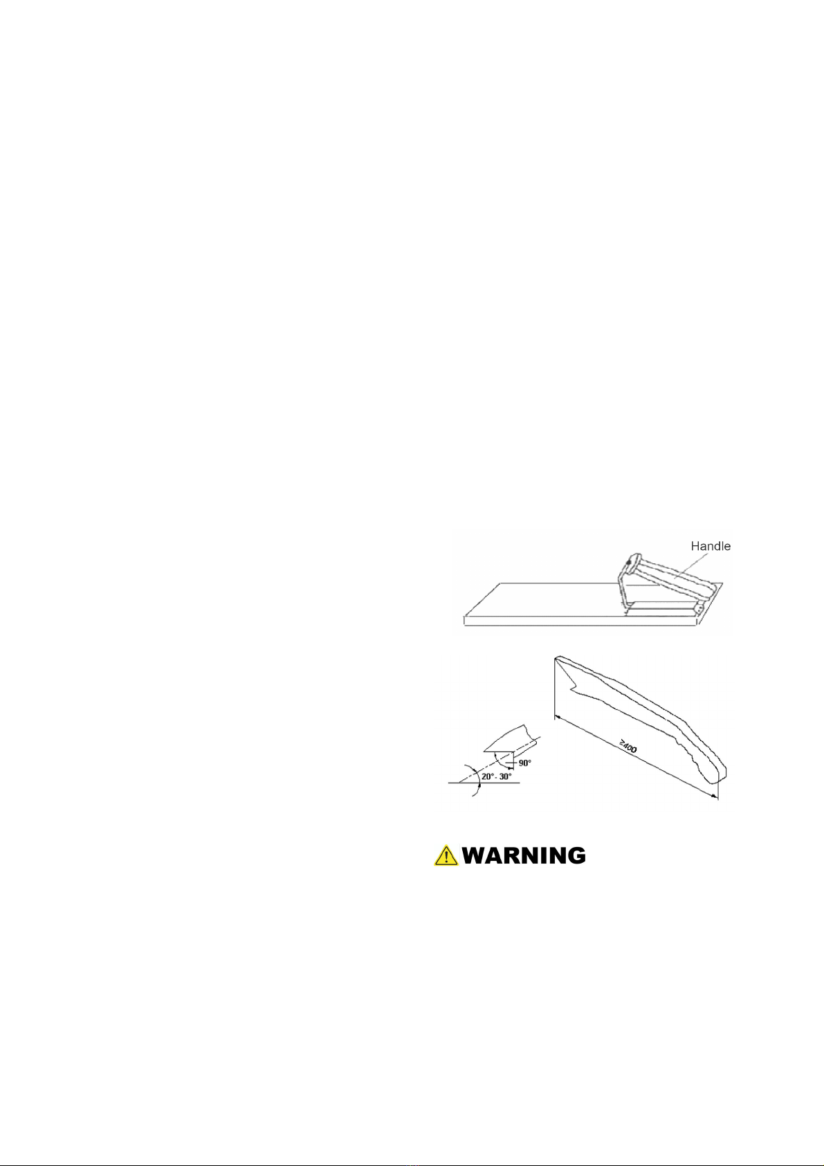
3. ALWAYS USE A PUSHSTICK OR PUSH
BLOCKS.
Push blocks or push sticks shall be used when
cutting small workpieces and in circumstances
where it is necessary to push the workpiece
against the fence;
4. NEVER PERFORM UNSAFE OPERATIONS.
Never perform any operations “free-hand” which
means using your hands to support or guide the
work piece. Always use either the fence or the
miter gauge to position and guide the work piece;

6
5. STAND TO THE SIDE WHEN FEEDING
MATERIAL.
Never stand or have any part of your body in line
withthepathofthesawblade;
6. USE CAUTION WHEN REACHING FOR
OBJECTS.
Never reach behind or over the cutting tool with
either hand for any reason;
7. SAFE CROSSCUTTING OPERATIONS.
Move the rip fence out of the way when
crosscutting;
8. ENSURE CORRECT FEEDING OF MATERIAL.
Feed the work into the blade against the direction
of rotation;
9. CORRECT USAGE WITH THE FENCE.
Never use the fence as a cut-off gauge when you
are cross-cutting;
10. ALWAYS TURN THE POWER TO THE "OFF"
POSITION.
When attempting to free a stalled saw blade,
always turn the saw to the "off" position and
disconnect it from the power source.
11. PROVIDE ADEQUATE SUPPORT.
To the rear and sides of the table saw for wide or
long work pieces;
12. AVOID KICKBACKS.
Avoid kickbacks (work thrown back towards you)
by keeping the blade sharp, by keeping the rip
fence parallel to the saw blade, by keeping the
splitter and anti-kickback fingers and guard in place
and operating, by not releasing work before it is
pushed all the way past the saw blade, and by not
ripping work that is twisted or warped or does not
have a straight edge to guide along the fence;
13. AVOID AWKWARD OPERATIONS.
Avoid awkward operations and hand positions
where a sudden slip could cause your hand to
move into the spinning blade;
14. BLADE REQUIREMENTS.
Only correctly sharpened saw blades
manufactured in accordance with the requirements
of EN 847-1:2005 shall be used;
15. CORRECT SAW BLADE USAGE.
No saw blade shall be used where the maximum
marked speed is lower than the maximum
rotational speed of the saw spindle;
16. CHIP AND DUST.
The machine shall be connected to an external
chip and dust extraction system;
The dust extraction equipment is to be switched on
before commencing machining;
17. CHECK
Periodically check the brake function to make sure
the completed stop time of the saw blade is less
than 10 seconds.
4.3 Residual Risks
1. Take precautions to reduce the hazard of
inhalation of harmful dusts (e.g. wearing a dust
mask);
2. Wear ear protection to prevent hearing loss;
3. Always wear safety glasses. Also use a face
or dust mask if the cutting operation is dusty;
4. Protect against the hazard of handling saw
blades when doing maintenance;
5. Do not attempt to remove chips while the
blade is still moving;
6. Do not use the machine unless all of the
guards and other safety devices necessary for
machining are in good working order;
4.4 Safety Equipments
Apushblock(Fig. 2) and A push stick (Fig. 3)
must be used
Fig. 2
Fig. 3
If the workpieces is less then 120 mm, you
must use the push stick to prevent your hands
from getting too close to the saw blade.
Push block must be used to cut narrow
workpieces and, when necessary, to push the
workpiece against the fence. A push block can
be easily made by the operator as shown in Fig.
2.

7
5. Installation of the Machine
5.1 Transportation of Machines
5.1.1 Transportation and Storage
Anti-rust and shock-proofing measures were taken
during packaging. The machine is able to endure
temperature variations of -13 to 130 degrees F. Do
not expose the machine to rain and avoid
damaging the packaging during transportation and
storage.
While transporting or handling the machine, be
careful and let the activity be done by qualified
personnel especially trained for this kind of
activity!
While the machine is being loaded or unloaded,
make sure that no person or subject gets
injured by the machine!
Select proper transportation device according
to the weight of the machine. Make sure the
lifting capacity of the transportation device is
competent for the weight of the machine.
5.1.2 Transportation before unpacking
As standard, the machine is packed in a robust
cardboard box. Fig. 4 shows the tool can be used
to transport the packing box.
Fig. 4
5.2 Unpacking
Your machine was carefully packaged for safe
transportation. Remove the packaging materials
from around your machine and inspect it. If you
discover the machine is damaged, please
immediately call Customer Service for advice.
Save the containers and all packing materials for
possible inspection by the carrier or its agent.
Otherwise, filing a freight claim can be difficult.
Note: If you can't find an item on this list, check
the mounting location on the machine or
examine the packaging materials carefully.
Occasionally we pre-install certain components
for shipping purposes, or in other packing;

8
5.3 Contents of C200-30
Main machine box contents:
(Fig. 4-1-----Fig. 4-4)
A. Main table saw unit……..………..………1
B. Motor cover……….……..………..………1
C. Left extension table……..………………1
D. Right extension table…………………1
E. Saw blade…………………………………1
F. Blade guard assembly…………………1
G. Riving knife……..………..……..………1
H. Hand wheel……………..………..………1
I. Lock knob..….. ………..………..………1
J. Hex wrench set (eight pieces)…..…1
K. Wrench open-end 17/23 mm…..………1
L. Miter gauge…..………..…..…..………1
M. Dado Blade Flange…………………….1
N. Push stick…..……..…..………..………1
O. Dado table insert……..………..………1
Fig. 4-1
Fig. 4-2
Fig. 4-3
HON
M
L
K
J
I
Fig. 4-4
C
D

9
Fence box contents:(Fig. 4-5)
A. Fence body…..…..………………..……1
B. Fence………………………………..…..1
Fig. 4-5
Flexible hose box contents:(Fig. 4-6)
A. Flexible hose (length 2.5 m)…………...1
B. Hose bracket ……………………………..1
Fig. 4-6
Rail box contents:(Fig. 4-7)
A. Rear rail……………..……………..……1
B. Front rail…………….…………..………1
C. Front rail rectangular tube………...…1
D. Front rail tape scale………………….…1
Fig. 4-7
5.4 Safety Measure before Installation
It is important to maintain a free area of 2.5 ft.
around the machine, which is required for the
working place. If any long material is machined, it is
necessary to have a sufficient room in front of the
machine as well behind it in the places of material
input and output.

10
5.5 Installation
Before beginning assembly, take note of the
following precautions and suggestions.
The machine is bolted to the pallet, before
attempting any of the assembly procedures
remove all of the loose parts and hardware from
the inside of the machine and unbolt the machine
from the pallet.
----- FLOOR: This tool distributes a large amount of
weight over a small area. Make certain that the
floor is capable of supporting both the weight of the
machine and the operator. The floor should also be
a level surface. If the unit wobbles or rocks once in
place, be sure to eliminate by using shims.
-----WORKING CLEARANCES: Take into
consideration the size of the material to be
processed. Make sure that you allow enough
space for you to operate the machine freely.
-----OUTLET PLACEMENT: Outlets should be
located close enough to the machine so that the
power cord or extension cord is not in an area
where it would cause a tripping hazard. Be sure to
observe all electrical codes if installing new circuits
and/or outlets.
DO NOT assemble the machine until you are
certain that the machine is not plugged in and
the power switch is in the OFF position.
DO NOT connect the machine to the power
source until the machine is completely
assembled and you read and understand the
entire User Manual.
5.5.1Remove the accessories
Remove all attachments fixed to pallet.
Remove all accessories or packages contained in
the cabinet.
5.5.2 Motor cover install
Install the motor cover by inserting the door pins
into the hinge sockets on the cabinet as shown in
Fig. 5;
Fig. 5
5.5.3 Hand wheel handle install
Install the handle into the Blade Tilt & Elevation
hand wheel as shown in Fig. 6.
Fig. 6
5.5.4 Extension tables install
Refer to Fig. 7.
1. Remove the screws from the sides of the main
table;
2. Inspect the extension tables and main table
mating surfaces for burrs or foreign materials that
may inhibit assembly;
3. The mating edges of the tables and the table
must be clean, smooth, and flat, use a wire brush
or sand paper if necessary to clean up the edges,
this step will ensure that the tables mount properly
to the main table;
4. Attach the tables to the main table with the
screws removed in step 1;
5. Place the straightedge across the extension
tables and main table to make sure that the table
surface is flat;
If the outside end of extension tables tilts down or
up, use a strip of masking tape to fill the play
between the extension table and the main table.
Fig. 7

11
5.5.5 Install the rail & fence
1. Install the rear rail , front rail, tube, and extension
table. Before tightening the fasteners,check to
make sure the top edge of rear rail is flush with the
lowest edge of both T-bolts,so the miter gauge will
slide smoothly when installed later, as shown in Fig.
8.
2. Place the fence on the rails on the right hand
side of blade as shown in Fig.9.
Fig. 8
Fig. 9
Make sure the cam foot contacts the cam on
the fence lock handle before you place the
fence on the rail, otherwise the fence will not
lock into the rail tube, refer to Fig. 9.
3. Checking fence parallelism
Refer to Fig. 10.
----Slide the fence along the rail , if it drags across
the table, then adjust the foot at the rear of the
fence to raise the fence off of the table just enough,
so that the gap between the fence, and the table is
even from front to back;
----Slide the fence up, against the right hand edge
of the miter slot, and lock it in place, examine how
the fence lines up with the miter slot;
Fig. 10
It's permissible for the back of the fence to
pivot outward not more than 1/64" from being
parallel to the blade. This creates a slightly
larger opening between the fence and the blade,
at the rear of the blade, to reduce the risk of
workpiece binding or burning as it is fed
through the cut. Many woodworkers
intentionally set up their fence in this manner.
Keep this in mind before adjusting your fence.
4. Install the fence scale
Refer to Fig. 11.
Fig. 11

12
Slide the fence up against the saw blade, and lock
it in place; Place the front rail tape scale on the
fence tube, make sure it is parallel with the tube,
and the “0” end is directly under the red line on the
pointer window as shown; lightly mark the “0”
location on the tube with a pencil, then remove the
fence; peel the tape and carefully align the “0” mark
on the scale with the pencil mark you made;
If you make a mistake, loosen the screws on the
point window, slide the fence against the blade,
adjust the pointer window, so the red line on the
window is over the “0” mark on the tape, then
secure the screws;
5.5.6 Install the switch
Install the magnetic switch onto the bottom, left
hand side of the front rail tube.
Refer to Fig. 12.
Fig. 12
5.5.7 Install the blade
1. Make sure the saw is in the "off" position before
installing the blade. Remove the table insert;
2. Rise the arbor all the way up and set the blade
angle at 0º;
3. Remove the arbor nut and arbor flange from the
arbor, slide on the included 10" saw blade, making
sure the teeth face the front of the saw, then install
the arbor flange and arbor nut onto the blade;
4. Put on a pair of heavy leather gloves and use the
included arbor wrenches to tighten the arbor nut
(turn clockwise to tighten), refer to Fig. 13.
Fig. 13
5.5.8 Install the blade guard
1. Reinstall the insert, slide the knurled knob out
(refer to Fig. 14) and rotate it forward so it engages
the upper bracket.
Fig. 14
2. Slide the blade guard spreader all the way down
into the block, then rotate the knurled knob so it
disengages the bracket and the locking pin
engages the hole in the center of the spreader.
3. Give the spreader an upward tug to verify that it
is locked in the blade guard, when properly
installed, refer to Fig, 15
Fig. 15
Check that saw blade clamping system is tight
before operating the machine.

13
4. Place a straightedge against the blade and the
spreader. When properly aligned, the
spreader/riving knife will be in the "alignment
zone," refer to Fig. 16, and will be parallel with the
blade.
Fig. 16
After changing a saw blade, always check that the
Riving knife or Blade Guard is correctly set!
1. Riving knives shall be manufactured from steel
with an ultimate tensile strength of 580 N/mm²or
of a comparable material, have flat sides (within
0,1 mm per 100 mm) and shall have a thickness
less than the width of cut (kerf) and at least 0,2mm
greater than the saw blade plate. As shown in Fig.
17
Fig. 17
Key:
e riving knife thickness
b saw blade blade
B kerf (width of saw blade cut)
2. The distance of the riving knife from the gear rim
must be between 3 mm and 8 mm. measured
radially through the centre of the saw spindle. As
shown in Fig.18
Fig. 18
3. The highest point of the riving knife must be set
beneath the topmost teeth.
5.5.9 Extraction system
Dust collector device should be prepared by
customer.
The main dust outlet diameter is 100mm (4"). as
shown in Fig. 19
Fit the flexible hose to the rear rail:
1. Mount the hose bracket to the rear rail with
screw A,washer B and wing nut C.
2. Fit the flexible hose as Fig.19.
Fig. 19
The air current speed is 3937 FPM (20 m/s) for the
vacuum suction dust emission index. When the air
current speed of dust collector device (in
accordance with EN 12779:2004) is not lower than
3937 FPM (20 m/s), ensure that the machine can
be normally exhausted.
1. Required air flow: 470 CFM (800 m³/h).
2. Ensure pressure drop of each dust collector
outlet carrying air current speed: 1100Pa
3. Dry chips: 3937 FPM (20 m/s).
4. Wet chips: 5511 FPM (28 m/s). (water content
is equal to 18%)

14
5.5.10 Electrical installation
Wiring should only be done by professional
electricians. Always make sure the machine is
properly grounded.
All wiring in the cabinets should be protected
against direct contact to at least IP2X when
finishing electrical installation.
All exposed conductive parts should be
connected to the protective bonding circuit.
Close and lock the door of cabinets.
Enough space should be kept around the
machine to allow for convenient maintenance.
The machine should be installed in a workshop
with good illumination and ventilation.
Over-voltage protection device should be
provided by end user.
ELECTRICAL DIAGRAM
Check that the voltage and frequency required by
the machine, which is shown on the machine’s
name plate, corresponds to the electric power
supply voltage and frequency.
A circuit breaker shall be used for supplying
electrical power to this machine in order to protect
the user for indirect shock.
Wiring:
Finish electrical connection according to the
electrical drawings.
The wiring in place should refer to the
requirements of Clause 13 (Wring practices) of EN
60204-1:2006.
Checking:
After finishing the wiring, check the following items:
Check the wiring of machine.
Check the direction of motors and change wiring if
necessary.
Check the components for defects, such as
looseness or damage.
Check the functions of safety devices.
115V Wiring Diagram 230V Wiring Diagram

15
Rewiring for 230V Power
(Note: This chapter is only available for
the table saw with dual voltages.)
The power must be disconnected before any
wiring operations!
This table saw can be used for 115V or 230V power.
It comes from the factory pre-wired for 115V, so if
you want to use it for 230V, you need to take off the
switch box, replace the circuit breaker, switch panel
and power cable, rewire the parts and adjust the
wiring of the motor. The detailed steps are as
followings:
The new circuit breaker and switch panel used
for 230V are provided together with the table
saw, but the power cable with plug (6-20P) for
230V needs to be purchased separately.
1. As shown in Fig. 20, unscrew the screws (A) and
loosen the strain reliefs (B), then take off the switch
box.
Since the terminals’ wiring positions in the
switch box are same for 115V and 230V, we
suggest you take photos of the terminals’ wiring
positions as a reference for the following
rewiring. Also if you encounter any wiring
problems, please refer to Fig. 21 or the Electrical
Diagram.
Fig. 20
Fig. 21
2. Disconnect all the terminals’ wiring inside the
switch box and the earth terminal’s wiring of the
power cable.
a. Replace the circuit breaker (by loosening the
protection cap) with the new one that is used for
230V, then tighten the protection cap.
b. As shown in Fig. 22, unscrew the screws (C) and
replace the switch panel with the new one that is
used for 230V, then tighten the screws.
c. Replace the whole power cable with the new one
that has the plug of 6-20P and tighten the strain
reliefs.
d. Then referring to Fig. 21 or the Electrical Diagram
or the photos you’ve take in Step 1, rewire all the
cables to the terminals correctly. Mount the switch
box back by tightening the screws.
Fig. 22
3. Adjust the wiring of the motor according to the
Electrical Diagram.

16
6. Adjustment
Before operation, the machine should be
carefully adjusted for the best performance.
Please make adjustments as following:
6.1 Blade Elevation and Tilting Mechanism
To raise or lower the blade, loosen lock knob (C) As
showninFig.20and turn the elevation hand wheel
(D). When desired height is obtained, retighten lock
knob. The blade should be raised 1/8” to 1/4” above
the top surface of the material being cut. With hollow
ground blades the blade should be raised to the
maximum to provide chip clearance. To tilt the saw
blade, loosen lock knob (B) and turn the hand wheel
(A). When desired angle is obtained, retighten lock
knob. Refer to Fig. 20.
Fig. 20
6.2 Adjusting Rip Fence
1. The rip fence must be perfectly aligned with the
table T-slot. To verify this, align the edge of the rip
fence with the table T-slot and lower the locking
lever (A) Fig. 21 to lock it into place. Check to see if
the edge of the rip fence and the table T-slot are
parallel. If they are not parallel, unlock the rip fence
and turn it upside down. Adjust the set screws (H)
as shown in Fig.22in or out, verify your adjustment,
repeat if necessary.
2. The lock lever pressure can be adjusted by
loosening the front lock nuts (B) as shown in Fig.21
and adjusting the set screws (C) the same amount.
Make sure the fence remains parallel with the table
T-slot. Retighten lock nuts.
3. To set the fence perpendicular to the table, place
a square on the table and against the side of the
fence, loosen the top lock nuts (D) and adjust the
setscrews (E) until the fence is perpendicular.
Retighten lock nuts.
4. The pointer window (F) as shown in Fig.21
position can be adjusted if needed. Loosen the pan
head screws (G), reposition the pointer window and
retighten pan head screws.
Fig. 21
Fig. 22
6.3 Aligning Table T-slot Parallel with Blade
1, The table T-slot must be aligned parallel with the
blade. Using a combination square measure the
distance from the back edge of the blade to the table
T-slot. Pivot the blade forward 180º and re-measure
the distance using the exact same point on the
blade. The difference between both measurements
must be less than 0.2mm. Refer to Fig. 23.

17
If an adjustment is necessary, loosen the screws
which are fixed to the table (as indicated by the
pointing arrows) and make the needed adjustment
until both measurements are equal or less than 0.2
mm. and retighten the screws. Refer to Fig. 24.
Fig. 23
Fig. 24
6.4 Adjusting 45°and 90°Positive Stops
The tilt mechanism has adjustable stops for vertical
and 45°. The machine comes factory-set but should
adjustment be required, loosen and adjust the stops
and retighten the stops. Refer to Fig. 25.
Fig. 25
6.5 Aligning Blade Guard Splitter or Riving
Knife with Blade
The blade guard splitter and/or riving knife must be
aligned with the blade. If not properly aligned, the
splitter/riving knife will force the workpiece sideways
during the cut, increasing risk of kickback. Place a
straightedge against the blade and the splitter or
riving knife and check for parallelism. If an
adjustment is needed, the mounting position can be
adjusted into alignment with the blade using the
adjustment set screws (A) Refer to Fig. 26.
1. Disconect saw from power source.
2. Remove the table insert.
3. Loosen the upper and lower cap screws (B), then
adjust the 4 set screws in or out until the alignment
is perfectly parallel.
4. Reinstall the table insert.
Fig. 26

18
7. Operations
7.1 Electrical Operation (Fig. 27)
ON Button: Starts the motor.
Hole for safety pin: When the pin is installed, it
disables the ON Button to prevent accidental
startup. STOP Button: Stops machine.
Fig. 27
7.2 Safety Precautions before Operations
The operation of power tools involves a certain
amount of hazard for the operator. Before
attempting regular work we recommend you get the
feel of operations using scrap lumber to check
settings. Read the entire instructions before you
start to cut the workpiece. Always pay attention to
safety precautions to avoid personal injury.
7.3 Operation
Plain sawing includes ripping and crosscutting, plus
a few other standard operations of a fundamental
nature. The following methods feature safety. As
with all power tools there is a certain amount of
hazard involved with the operation and use of the
tool. Using the tool with the respect and caution
demanded as far as safety precautions are
concerned will considerably lessen the possibility of
personal injury. However, if normal safety
precautions are overlooked or completely ignored,
personal injury to the operator can occur. It is good
practice to make trial cuts using scrap material when
setting up your saw for operation.
7.4 Crosscutting
Crosscutting requires the use of the miter gauge to
position and guide the work. Place the work against
the miter gauge and advance both the miter gauge
and work toward the saw blade. The miter gauge
may be used in either table slot, however, most
operators prefer the left groove for average work.
When bevel cutting (blade tilted), use the table
groove that does not cause interference of your
hand or miter gauge with the saw blade guard.
Start the cut slowly and hold the work firmly against
the miter gauge and the table. One of the rules in
running a saw is that you never hang onto or touch a
free piece of work. Hold the supported piece, not the
free piece that is cut off. The feed in crosscutting
continues until the work is cut in two, then the miter
gauge and work are pulled back to the starting point.
Before pulling the work back, it is good practice to
give the work a little sideways shift to move the work
slightly away from the saw blade.
Never pick up any short length of free work from the
table while the saw is running. A smart operator
never touches a cut-off piece unless it is at least a
foot long. Never use the fence as a cut-off gauge
when crosscutting. Never use the miter gauge in
combination with the rip fence.
7.5 Ripping
Ripping is the operation of making a lengthwise cut
through a board, and the rip fence is used to
position and guide the work. One edge of the work
rides against the rip fence while the flat side of the
board rests on the table. Since the work is pushed
along the fence, it must have a straight edge and
make solid contact with the table. The saw guard
must be used. The guard has anti-kickback fingers
and a splitter to prevent the saw kerf from closing.
Start the motor and advance the work holding it
down and against the fence. Never, stand in the line
of the saw cut when ripping. Hold the work with both
hands and push it along the fence and into the saw
blade. The work can then be fed through the saw
blade with one or two hands.
When this is done, the work will either stay on the
table, tilt up slightly and be caught by the rear end of
the guard or slide off the table to the floor.
Alternately, the feed can continue to the end of the
table, after which the work is lifted and brought back
along the outside edge of the fence. The waste
stock remains on the table and is not touched with
the hands until the saw is stopped unless it is a large
piece allowing safe removal.
This manual suits for next models
1
Table of contents
Other HARVEY Saw manuals

HARVEY
HARVEY C300-30 User manual

HARVEY
HARVEY HW110S-36G User manual

HARVEY
HARVEY Axminster AT254LTS User manual

HARVEY
HARVEY C300-30 User manual

HARVEY
HARVEY C-18VS User manual

HARVEY
HARVEY C14 User manual

HARVEY
HARVEY HW110TC User manual

HARVEY
HARVEY HW615 User manual

HARVEY
HARVEY HW110LC-36 User manual

HARVEY
HARVEY HPS1600E User manual