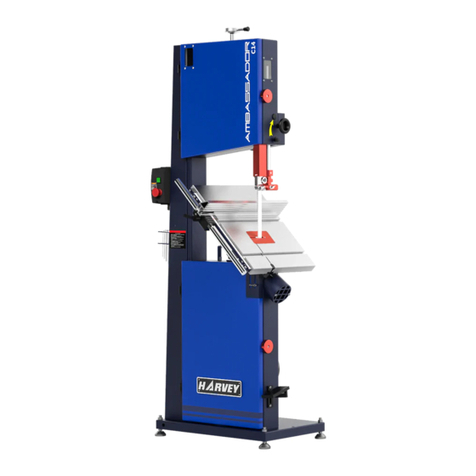
HARVEY C-18VS User manual

INSTRUCTION MANUAL
Woodworking Band Saw
MODEL:C-18VS
Harvey Industries Co.,Ltd.

1
Table of Contents
1、SAFETY RULES 2
1.1 LARGE ELECTRIC TOOLS SAFETY-------------------------------------------------------------2
1.2 WOODWORKING BAND SAW SECURITY ----------------------------------------------------2
2、UNPACKING AND CHECKING CONTENTS -------------------------------------------------3
3、GETTING TO KNOW YOUR BANDSAW ------------------------------------------------------4
4、SPECIFICATION--------------------------------------------------------------------------------------4
5、ELECTRICAL REQUIREMENTS &MAGNETIC SWITCH OPERATIONS ----------5
6、ASSEMBLY 6-8
6.1 DISASSEMBLING FLOOR AMOUNTING BOLTS ---------------------------------------------6
6.2 ASSEMBLING MOTOR ------------------------------------------------------------------------------6
6.3 ASSEMBLING WORKING TABLE ----------------------------------------------------------------6
6.4 ASSEMBLING THE GAS SPRING -----------------------------------------------------------------7
6.5 ASSEMBLING FENCE -------------------------------------------------------------------------------7
6.6 ASSEMBLING TOOL STORAGE HOOKS -------------------------------------------------------7
6.7 ASSEMBLING SAW BLADE -----------------------------------------------------------------------8
6.8 SWITCH OF THE DOOR-----------------------------------------------------------------------------8
7、ADJUSTMENT 9-10
7.1 ADJUSTING THE SAW BLADE TENSIONS ----------------------------------------------------9
7.2 ADJUSTING UPPER AND LOWER SAW BLADE GUIDE -----------------------------------9
7.3 ADJUSTING WORKING TABLE -----------------------------------------------------------------10
7.4 ADJUSTING FENCE --------------------------------------------------------------------------------10
7.5 ADJUSTING THE TABLE +15 to -45 POSITION STO P--------------------------------------10
8、OPERATION 11-12
8.1 CROSSCUTTING ------------------------------------------------------------------------------------11
8.2 RIPPING -----------------------------------------------------------------------------------------------11
8.3 RESAWING -------------------------------------------------------------------------------------------12
8.4 CUTTING CURVES ---------------------------------------------------------------------------------12
8.5 STACKED CUTS ------------------------------------------------------------------------------------12
9、MAINTENANCE 13
9.1 LUBRICATION --------------------------------------------------------------------------------------13
9.2 CLEANING -------------------------------------------------------------------------------------------13
9.3 WHEEL BRUSH -------------------------------------------------------------------------------------13
10、ASSEMBLY DRAWING-------------------------------------------------------------------------14-18
11、PARTS LISTS--------------------------------------------------------------------------------------19-22
12、ELECTRICAL PRINCIPLE CHART---------------------------------------------------------23

2
Safety Rules
LARGE ELECTRIC TOOLS SAFETY
1. Know your band saw
Get up manual instruction for machine maintenance manual in all points before starting any
maintenance work.
2. Ground connection
This machine with grounding plug ,must ensure that ground .Green or green rolling line of yellow
color for the grounding line , can never make a mistake .
3. Use the shied
4. Remove the wrench
Form a good habit: to ensure adjustment tools , such as start-up go forward all the wrench .
5. Keep the working area clean
In a timely manner to clean the ground to ensure that the ground is not wet.
6. To avoid dangerous working environment
Can't use machine in damp environment, also cannot expose machine in the rain.
7. Stay away from the children
All bystanders should keep a safe distance. With the working area.
8. Children shall be prohibited from entering the preparation
9. Use appropriate machine speed
10. Use the right tools
11. Wear suitable work
Can't through greater than loose clothing, gloves, tie or wearing jewelry.
12. Always wear protective glasses
13. Don't get too close to the workspace
14. Careful maintenance machine
Always keep the machine clean, in order to assure the best the best performance, in a timely
manner in accordance with the specifications and lubrication and replace the attachment.
15. Deenergization
Before maintenance, should ensure that power off.
16. To avoid accidental activation
Before access to the power supply, do not contact switch.
17. Use the specified in the attachment
18. Never stand on the machine
19. Regularly check damaged parts
20. Never leave the machine before machine did not stop completely
Woodworking band saw machine safety
1. Before removing the desktop batten, always ensure the stop of the saw blade.
2. Always make sure that the hands and fingers away from the blade.
3. Ban try sawing logs directly, because there is no a flat base surface logs, if use the appropriate
support device can be.
4. Always firmly grip the wood and then feed close to the saw blade at uniform speed.
5. If, after cutting blade is still in the wood, should first turn off the power.
6. Adjustment on saw card distance by cutting material about 1/8 ".

3
7. Check the size and model of the saw blade to satisfy the requirements of cutting.
8. To ensure that the saw blade tensioning force and the position has been adjusted in position.
9. The long curve cutting, make sure tension a little loose.
Unpacking and Checking Contents
The machine is shipped complete in one box!
Before discarding any packaging material, separate all “loose parts” and check each item
with“table of loose parts” to make sure all items are accounted for.
INSTRUCTION MANUAL
Wo o d w o r k i n g B a n d S a w
Model :HW618
Ha r v e y I ndu s t r i e s Co . , L t d .
1
23
4
8
5
6
7
ABCD
EFGH
I
J
K
L
Table of Loose Parts Table of Hardware Parts
NO Name Qty
NO Name Qty A. Hex wrench 5 mm 1
B. Hex wrench 4 mm 1
1. Band saw Assembly 1 C. Hex wrench 3 mm 1
2. Rip Fence Assembly 1 D. Hex wrench 2 mm 1
3. Tool Storage Hooks 1 E. Hex bolt m10*25 4
4. Main Table 1 F. Hex bolt 3/8-16*3/4 4
5. Motor 1 G. Button head screw m5*16 2
6. Motor Flange 1 H. Flat washer 10 8
7. Spring Assembly 1 I. Lock washer 10 8
8. Instruction Manual 1 J. Flat washer 5 2
K. Lock washer 5 2
L. Bottom screw 12×60 4

4
Getting To Know Your Band Saw
2
3
5
4
17
68
9
10
11
12
13
14
15
16
17
19
18
1. Tension Indicator Window 11. Blade Guide
2. Display 12. Rip Fence Assembly
3. Switch 13. Upper Dust Port 4″
4. Tool Storage Hooks 14. The workbench saw seam lock handle
5. Frame 15. Bottom screw
6. Blade Tension Lever 16. Blade Tracking Knob
7. Blade Tracking Window 17. Quick Release Blade Tension Lever
8. Iron Table 18. Supporting Spring Assembly
9. Foot brake 19. Motor
10. Blade Guide Adjustment Hand wheel
Specifications
Blade length (inch) 145″
Table tilt 0°to -20°
Max. cutting width (mm) 440
Max. cutting depth (mm) 360
Table size (mm) 510 * 510
Min. blade size 1/8″
Max. blade size 1″
Motor date 230V, 60HZ, 3HP

5
Electrical Requirements & Switch Operation
WARNING!
All electrical connections must be done by a qualified electrician. failure to comply may result in
serious injury! Adjustments or repairs-must be done with the machine disconnected from the
power source.failure to comply may result in serious injury!
POWER SUPPLY
Warning! This band saw came pre-wired for 230v
operation and must be connected to an appropriately
grounded 230v outlet as showen in fig. 1
GROUNDED
Warning! if outlet is not properly grounded, this band saw Fig. 1
can cause electrical shock.particularly when used in
damp locations. to avoid shock or fire, if the power
cord is worn or damaged in any way,have it replaced
immediately.not all outlets are properly grounded. if you
are not sure if your outlet is properly grounded, have it
checked by a qualified electrician.
Warning! To maintain proper grounding of your band saw.
do not remove or alter the grounding prong in any manner. Fig. 2
SAFETY SWITCH OPERATION
The operation box as shown in fig. 3 needs to be installed to side
of frame ,see assembly section in this manual for further instructions.
Do not turn the band saw on until all assembly and adjustment
instructions have been done.
As shown in figure 3:
Speed display (A) Stop button (B) Position switch(C)
Start button(D) Speed control knob(E)
To start the band saw, press the green start button (D) . and to
stop the band saw, press the red stop button (B).
Fig. 3
A
B
C
D
E

6
Assembly
The band saw is supplied partly assembled. Prior to use, the following items have to be
assembled!
disassembling floor amounting bolts
To be safe, we mounting the band saw to the pallet for
shipment, so firstly, you must remove the pallet and
slowly set the band saw into position by hardware,
fig 4.
You must mount your machine to rigid, level floor that
keep the machine stable.
Fig. 4
ASSEMBLING MOTOR
Firstly, you assemble motor (A) to the motor
flange (B)by hex bolt (E) 、lock washer (D)
and flat washer (C ) .secondly, assemble them
to the frame by hex bolt、lock washer
and flat washer. Then tension the v-belt
by motor gravity, Finally ,tighten the bolts.
In fig. 5.
Fig. 5
ASSEMBLING WORKING TABLE
Release the knob (A), then put the working
table assembly into the trunnion groove (B),
adjust the working table move freely, then
pre-tighten the nut (A)! In fig. 6.
Fig. 6
A
C
E
D
B
F
B
A

7
ASSEMBLING SPRING ASSEMBLY
Rotate the working table 20°
with anticlockwise, then install
the spring assembly into table
bottom and frame by
hardware (C,D,E),
in fig. 7.
Fig. 7
ASSEMBLING RIP FENCE
Slide the rip fence into the round tube,
and adjustment the rip fence parallel
with T-slot, and perpendicularity with
table, finally tighten the lock lever(B),
in fig 8.
Fig. 8
ASSEMBLING TOOL STORAGE HOOKS
Installing the operation box, keeping the face
of operation button is front, in fig 9.
Then installing the tool storage hooks into the
frame by button head screw (A) and flat washer (B).
Fig. 9
A
B
A
D
B
C
C
D
E
A
B

8
Saw blade assembly
First, remove the bedplate protection
plate(B) and Loosen handle(C), and then
saw blade (A) Bedplate crack on the
bedplate center and across the flywheel,
up and down on the up and down
Saw card center, then turn the saw blade
Tight grip (D), tensioning saw blade,
again Installed protection plate (B), at last
Lock knob (C). As shown in figure 10.
Fig. 10
Switch of the door
Pictured above 10 H for the limit switch; K for the key, when the door is open, start button is
failure, must limit switch closing rear can normal boot; On the other hand, when the normal work,
open the door, the motor stop working immediately.
Warning: the normal work, directly open the door is not allowed, because the rotation
inertia, saw wheel is still turning, when open the door after the full stop. Keep the limit
switch keyhole clean, especially the door of the keyhole.
AB
D
C
H
H
K
K

9
Adjustment
Adjust the tension of saw blade
1. Rotate quickly tension handle(E)
to the lock position, and turn the
saw blade tension handle (D) to
adjust Tension.
2. Slowly release the saw blade
tensioning lever until the saw
blade a slight oscillation.
3. Slowly increase the tension,
until the saw blade stopped
swinging, Then fixed tension
lock handle.
4. Adjust the trajectory of saw
blade, to ensure the saw blade
always in the center of the
pulley, and the most in the
wheel high location. As shown
in figure 11.
Fig. 11
Adjusting upper and lower blade guide
Blade guide factory before shipment has been
adjusted, the saw blade Is located in the center
of the blade guide and both sides Parallel to
the saw blade, if not, then you need to adjust:
1. Adjust the blade guide, as shown in fig. 12
loosen knob(B) and then adjust the blade
guide (C) the article about two porcelain(D)
and parallel blade guide(C), then lock knob(B),
using a wrench to loosen screw (G)adjust the
article round porcelain, screw (F) is to adjust
the saw before and after the whole movement
and swinging, loosen (E)adjust the steering,
all must lock all screw after the adjustment.. Fig. 12
2. Adjust the blade guide, as shown in figure 13. Loosen knob (B), mobile porcelain article, adjust
the blade is located in Article porcelain center with the blade guide (C) two parallel to the side,
Then lock knob (B), using a wrench to loosen (H) before, during and after the article can adjust
round porcelain (K) is to adjust the screw saw card before and after the whole mobile, all must
lock all after the adjustment screws.

A
B
DC
E
F
H
B
K
C
G
AB
D
C
F
E

10
ADJUSTING WORKING TABLE
First of all, loosen the handle (D) rotating
counter hand again(B), make the pointer to 0 °
then combination with Angle ruler to measure,
ensure straight on side and bedplate Angle is
90 °,if inconsistent, you may need to adjust,
indeed Pointer display scale is consistent with
the combined Angle ruler, then lock screw (C),
the most after the lock handle (D).
As shown in figure 13.
Fig. 13
ADJUSTING RIP FENCE
1. First turn on the Rip fence assembly(A)
close to the T slot(B) side;
2. Adjust the Rip fence assembly , make
the side parallel to T slot. as shown
in figure 14.
Fig. 14
ADJUSTING THE TABLE 0°--- POSITION STOP -20°
1. Loosen the workbench handle(C), rotate the
bedplate(A), make the Angle pointer to 0 °
then adjust the zero support (B), so that just
in 0 °to resist bedplate, then lock nut (E)
as shown in figure 15.
2. Loosen the workbench handle(C), rotate the
bedplate(A), make the Angle pointer to -20 °
then lock nut (D) as shown in figure 15.
Fig. 15
AB
90°
A
B
C
D
B
A
A
D
C
E

11
Operation
SAFETY PRECAUTIONS BEFORE OPERATION!!
The operation of power tools involves a certain amount of hazard for the operator. Before attempting regular
work we recommend you get the feel of operations using scrap lumber to check settings. Read entire
instructions before you start to cut work piece. Always pay attention to safety precautions to avoid personal
injury!
OPERATION
Band saw includes ripping and crosscutting, plus a few other standard operations of a fundamental nature.
The following methods feature safety. As with all power tools there is a certain amount of hazard involved
with the operation and use of tool. Using the tool with the respect and caution demanded as far as safety
precautions are overlooked or completely ignored, personal injury to the operator can develop. It is good
practice to make trial cuts using scrap material when setting up your operations.
CROSSCUTTING
Crosscutting is the process of cutting across the grain of wood,
for plywood and other processed wood, crosscutting simply
means cutting across the width of material.
1. mark the work piece on the edge where you want to begin the
cut.
2. adjust the blade guide assembly to the correct height and
make sure the miter gauge is set to 90.
3. move the fence out of the way, place the work piece evenly
against the miter gauge.
4.hold the work piece against the miter gauge and line up the
mark with the blade.
5. After all safety precautions have been met, turn the band saw on, Fig 16
slowly feed the work piece into the blade and continue the cut till
the blade is all the way through the work piece ,fig 17 shows a 90
crosscutting operation.
RIPPING
Ripping is the process of cutting with the grain of the wood stock,
for plywood and other processed wood, ripping simply means
cutting down the length of the work piece.
1. Adjust the fence to match the width of the cut on your work
piece and lock the fence in place.
2. Adjust the blade guide assembly to the correct height.
3. After all safety precautions have been met ,turn the band saw
on, slowly feed the work piece into the blade is completely
through the work piece.Fig18 shows a typical ripping operation. Fig 17
Note. If you are cutting narrow pieces, use a push stick to protect your fingers!

12
Operation
RESAWING
Re sawing is the process of cutting a board into two or
more thinner boards, the maximum board width that can be
re sawn is limited by the maxi-mum cutting height of the
band saw. One of the most important considerations when
resawing is blade selection, generally, the wider blade, the
better. In most applications, a hook or a skip tooth style
will be desirable. Choose blades with fewer teeth-per-inch,
because they offer large gullet capacities for clearing
saw-dust, reducing heat buildup and reducing strain
on the motor. In fig 19.Fig 18
CUTTING CURVES
When cutting curves, simultaneously feed and turn the
stock carefully so that the blade follows the layout line
without twisting, if a curve is so abrupt that it is necessary
to repeatedly back up and cut a new kerfs , use either a
narrower blade or a blade with more TPI (teeth per inch), or
make more relief cuts. Always make short cuts first, then
proceed to the longer cuts, relief cuts will also reduce the
chance that the blade will be pinched or twisted. Relief cuts
are cuts made through the waste portion of the work piece
and are stopped at the layout line. As you cut along the
layout line, waste wood is released from the work piece,
alleviating any pressure on the back of the blade, relief cuts Fig 19
also make backing the work piece out easier,
if needed. In fig. 20.
STACKED CUTS
One of the benefits of a band saw is its ability to cut
multiple copies of a particular shape by stacking a number
of work pieces together. Before making stacked cuts,
ensure that both the table and the blade are properly
adjusted to 90, otherwise, any error will be compounded. In
fig .21.
Fig. 20

13
Maintenance
This band saw requires very little maintenance other than minor lubrication and cleaning! The
following sections detail what will need to be done in order to assure continued operation of your
band saw.
8.1 LUBRICATION
Sealed and pre-lubricated ball bearings require no lubrication for the life of the bearings, all
bearings are standard sizes, and replacements can be purchased from our parts department or
a bearing supply store.
For adjustment controls, and occasional “shot” of light oil is just about all that is necessary, wipe
off any sawdust with a clean cloth, towel, or dry paint brush, and spray on the lubricant, no not
get oil on the pulleys or v-belt because it could cause belt deterioration and slipping.
8.2 CLEANING
Cleaning your band saw is relatively easy, vacuum excess wood chips and sawdust, and wipe
off the remaining dust with a dry cloth, if any resin has built up, use a resin dissolving cleaner to
remove it, treat all unpainted cast iron and steel with a non-staining lubricant after cleaning.
8.3 WHEEL BRUSH
The band saw is equipped with a lower wheel brush, the brush should be check daily and
cleaned when it becomes dirty, there is an adjustment bracket that allows the brush to be adjusted
for bristle wear.
Safety function
The interlocking guards shall be checked at every shift. Open the interlocking guard, the ma-chine
cannot be started. This indicates the interlocking function is correct. If the safety function
is failed, please ask the qualified personal immediately.

14
ASSEMBLY DRAWING

15
ASSEMBLY DRAWING

16
ASSEMBLY DRAWING

17
ASSEMBLY DRAWING

18
ASSEMBLY DRAWING

19
Parts List
NO.
Description
QTY
NO.
Description
QTY
101
Cap Screw M5×12
98
136
Flat washer 8
2
102
Hex Socket Cap Screw M6×12
24
137
Spring washer 8
2
103
Hinge
4
138
Cap Screw M8×16
2
104
Upper Door
1
139
Brush
2
105
Shockproof soft article
1
140
Lock Nut M4
1
106
Sight glass
2
141
Flat washer 4
1
107
Flat washer 5
14
142
Shockproof soft article
1
108
Lock Nut M5
10
143
Lock Nut M6
1
109
Blade Quick Release Label
1
144
Cap Screw M4×10
1
110
Adjusting Nut
1
145
Cover
1
111
Knob M8×35
1
146
Saw Frame
1
112
Lock Button
2
201
Spring Bracket
1
113
Cap Screw 6.5×12
2
202
Tensioning washer
2
114
Blade Guide Label
1
203
Tighten spring
1
115
Cap Screw M5×10
1
204
Tensioning washer
1
116
Position Indicator
1
205
Spring Bracket
1
117
Hex Cap Bolt M6×25
1
206
Top plate
1
118
Lock Nut M6
3
207
Flat washer 5
4
119
Support Plate
1
208
Spring washer 5
4
120
Lock Nut M8
1
209
Cap Screw M5×10
4
121
washer 8
2
210
Knob
1
122
Dust Guard
2
211
Handle
1
123
Flat washer 6
4
212
Gasket
1
124
Spring washer 6
4
213
Cam Shaft
1
125
Cap Screw M6×16
4
214
Set Screw M8×10
1
126
Lock Nut M12
4
215
Support Gasket
1
127
Anchor bolt M12×60
4
216
Spring washer 8
5
128
Cap Screw M5×16
2
217
Cap Screw M8×30
3
129
Spring washer 5
2
218
Lock Nut M12
2
130
Tool Bracket
1
219
Spring washer 12
2
131
Cap Screw M6×12
2
220
Flat washer 12
2
132
Tighten Indicator
1
221
Lock Nut M12
2
133
Brush Plate
2
222
Lock Nut M10
4
134
Flat washer 3
4
223
Square Screw
2
135
Screw 2.9×13
4
224
Square Shaft
1
Table of contents
Other HARVEY Saw manuals

HARVEY
HARVEY C300-30 User manual

HARVEY
HARVEY HW110TC User manual

HARVEY
HARVEY HW615 User manual

HARVEY
HARVEY C300-30 User manual

HARVEY
HARVEY HW110S-36G User manual

HARVEY
HARVEY HW110LC-36 User manual

HARVEY
HARVEY Axminster AT254LTS User manual

HARVEY
HARVEY C14 User manual

HARVEY
HARVEY HPS1600E User manual

HARVEY
HARVEY C200 Series User manual