HARVEY C14 User manual


CONTENTS
1. Safety------------------------------------------------------------------------------------------------------ 1
1.1 General Machine Safety.----------------------------------------------------------------------------- 1
1.2 Band Saw Safety.-------------------------------------------------------------------------------------- 1
2. Feature Identification-------------------------------------------------------------------------------- 2
3. Specifications------------------------------------------------------------------------------------------ 3
4. Unpacking and Setup-------------------------------------------------------------------------------- 4
4.1 Unpacking--------------------------------------------------------------------------------------------- -- 4
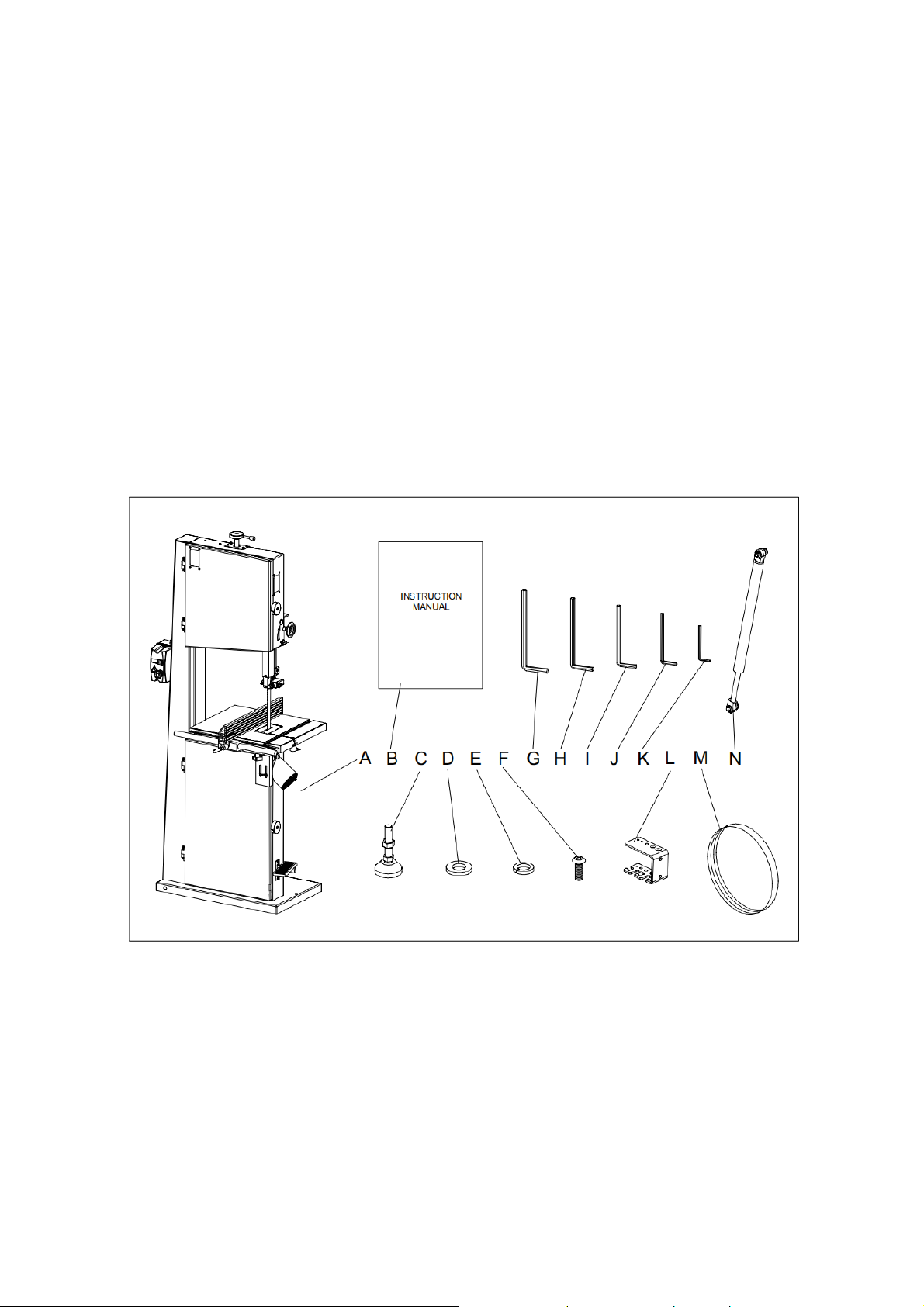
4.2 Checking Contents ----------------------------------------------------------------------------------- 4
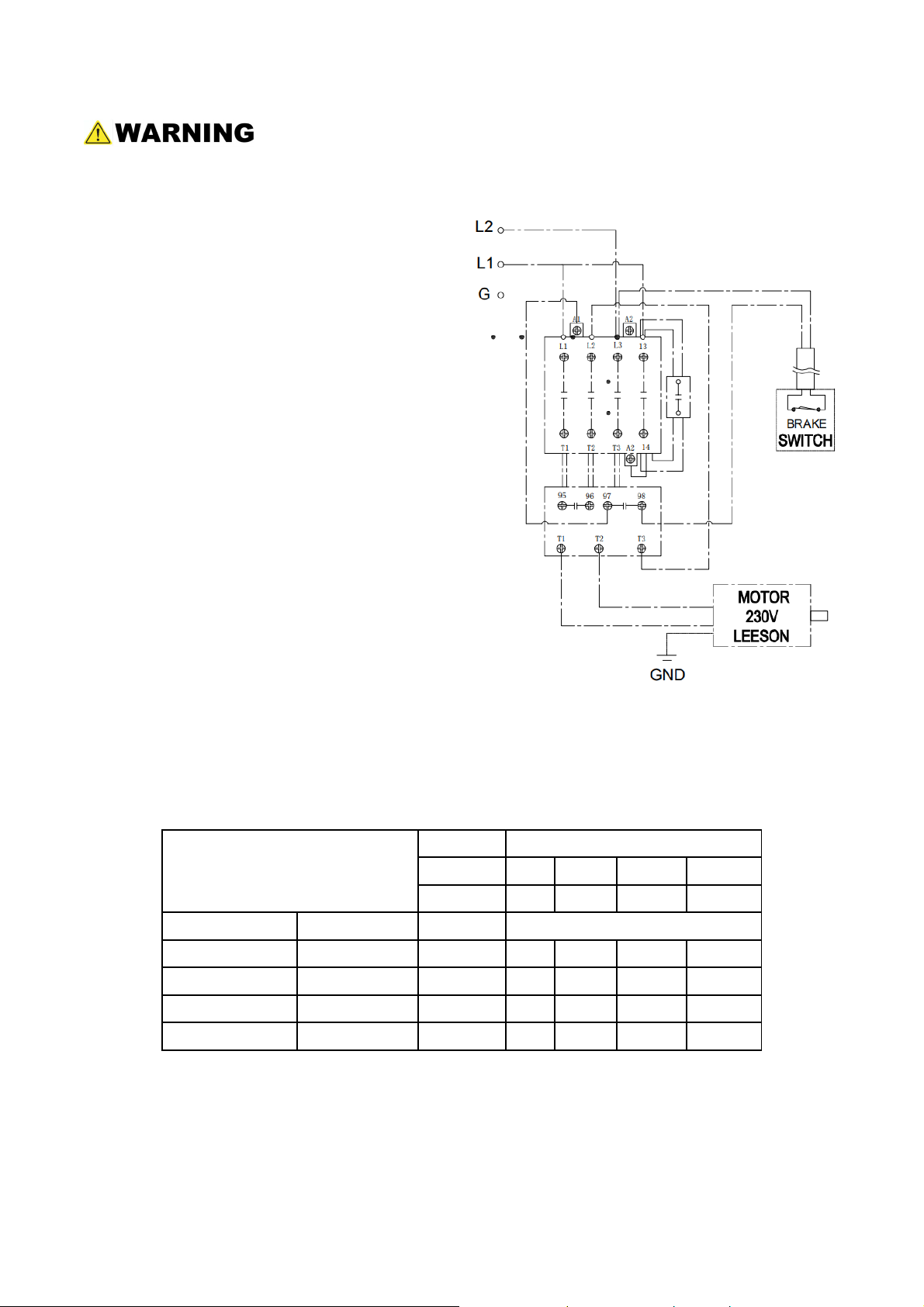
4.3 Power Supply------------------------------------------------------------------------------------------- 5
4.4 Grounding----------------------------------------------------------------------------------------------- 5
4.5 Extension Cords--------------------------------------------------------------------------------------- 5
4.6 Dust Collection----------------------------------------------------------------------------------------- 5
5. Assembly------------------------------------------------------------------------------------------------ 6
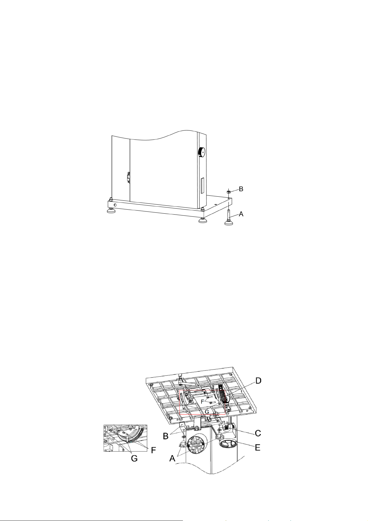
5.1 Stand Pad----------------------------------------------------------------------------------------------- 6
5.2 Work Table---------------------------------------------------------------------------------------------- 6
5.3 Spring Assembly--------------------------------------------------------------------------------------- 7
5.4 Rip Fence----------------------------------------------------------------------------------------------- 7
5.5 Tool Storage Hook------------------------------------------------------------------------------------- 7
5.6 Blade------------------------------------------------------------------------------------------------------ 8
6. Adjustment---------------------------------------------------------------------------------------------- 9
6.1 Blade------------------------------------------------------------------------------------------------------ 9
6.2 Blade Guide--------------------------------------------------------------------------------------------- 11
6.3 Work Table---------------------------------------------------------------------------------------------- 14
6.4 Fence----------------------------------------------------------------------------------------------------- 16
6.5 Belt Tension and Replacement--------------------------------------------------------------------- 18
7. Operation------------------------------------------------------------------------------------------------ 19
7.1 Switch----------------------------------------------------------------------------------------------------- 19
7.2 Brake Pedal--------------------------------------------------------------------------------------------- 19
8. Application---------------------------------------------------------------------------------------------- 20
8.1 Ripping --------------------------------------------------------------------------------------------------- 20
8.2 Crosscutting--------------------------------------------------------------------------------------------- 20
8.3 Resawing------------------------------------------------------------------------------------------------ 20
8.4 Curve Cutting------------------------------------------------------------------------------------------- 21
8.5 Blade Lead ---------------------------------------------------------------------------------------------- 21
9. Maintenance ----------------------------------------------------------------------------------------- 22
9.1 Lubrication----------------------------------------------------------------------------------------------- 22
9.2 Cleaning-------------------------------------------------------------------------------------------------- 22
9.3 Replacement-------------------------------------------------------------------------------------------- 22
9.4 Wheel Brush-------------------------------------------------------------------------------------------- 22
10. Trouble Shooting------------------------------------------------------------------------------------ 23
11. Exploded View and Parts List------------------------------------------------------------------ 25

1
1. Safety
1.1 General Machine Safety
1. For your own safety, read the user manual before operating the band saw.
2. This machine must be properly grounded to help prevent electrical shock and possible
fatal injury.
3. Form a habit of checking to see that the keys and the adjusting wrenches are removed
from the machine before turning it on.
4. Keep the work area clean. Cluttered areas and benches invite accidents.
5. Do not use in a dangerous environment. Do not expose the machine to rain or use in wet
or damp locations. Keep the work area well lighted.
6. Keep visitors a safe distance from the work area.
7. Children shall be prohibited from entering the working area.
8. Use appropriate feed speed, use the right tools.
9. Before operating the band saw, remove tie, rings, watches and other jewelry, and roll
sleeves up past the elbows. Remove all loose clothing and confine long hair.
10. Always wear protective glasses.
11. Don't get too close to the workspace.
12. Maintain machine and tools with care. Keep the blades sharp and clean for the best and
safest performance. Follow instructions for lubricating and cleaning.
13. Disconnect the machine from the power supply before maintenance.
14. Avoid accidental activation. Make certain the switch is in the OFF position before
connecting the machine to the power supply.
15. Use recommended accessories; improper accessories may be hazardous.
16. Never stand on the machine.
17. Regularly check those parts that are easily worn.
18. Never leave the machine running unattended. Turn the power off and do not leave the
band saw until the blade comes to a complete stop.
1.2 Band Saw Safety
1. Before removing the insert, always ensure the blade is not moving.
2. Always make sure that hands and fingers are away from the blade.
3. Never cut round stock without an appropriate supporting tool.
4. Hold stock firmly and feed at a stable speed.
5. If the blade is still in the wood after cutting, you should turn off the power immediately.
6. Adjust the upper blade guide to approximately1/8”above the work piece.
7. Check the size and model of the blade to meet the cutting needs of your project.
8. Make sure the blade tension and the tracking and blade guides are all properly adjusted.
9. Keep the tension a little loose when cutting long curved stock.
If precautions are not heeded, it may result in serious injury or possibly even death.

2
2. Feature Identification
Fig.1
1 Upper Wheel 15 Brake Pedal
2 Upper Door 16 Blade Tension Adjustment Hand Wheel
3 Switch Panel 17 Guide Post Locking Handle
4 Tool Storage Hooks 18 Rip Fence
5 Brush 19 Kerf lock handle
6 Lower Door 20 Upper Dust Port
7 Motor Pulley 21 Bottom screw
8 Lower Wheel 22 Tracking Knob
9 Window 23 Blade Tension Level
10 Door Locking Knob 24 Supporting Spring Assembly
11 Guide Post Adjustment Hand Wheel 25 Table Tilt Hand Wheel
12 Upper Blade Guide 26 Belt Tension Blot
13 Table Insert 27 Motor
14 Work Table 28 Lower Dust Port

3
3. Specifications
Model C14
Power 2.2 kW 3HP
Rated Voltage 230 V
Phase 1-Ph
Frequency 50 Hz 60 Hz
Full-Load Current 12.8 A
Wheel Dia. 350 mm 14″
Blade Length 3175 mm 125 ″
Blade Width 3-25 mm 1/8 - 1″
Speed of Saw Blade 1050 m/min
Max. Cutting Height 350 mm 14″
Throat Capacity 330 mm 13″
Fence Plate Height 14/80 mm 1/2” / 3″
Work Table Size 500×400 mm 19-3/4×15-3/4″
Work Table Height 870 mm 34-1/4″
Foot Size 610×400 mm 24″×15-3/4″
Total Height 1800 mm 71″
Net Weight 150 kg 330 lbs
Gross Weight 170 kg 374 lbs
Packing Size 750×495×1920 mm 29-1/2x19-1/2x75-5/8″
Notice to California Residents: This product can expose you to wood dust, which is known to
the State of California to cause cancer. For more information, go to
www.P65Warnings.ca.gov.

4
4. Unpacking and Setup
The machine is shipped completely in one carton.
4.1 Unpacking
Remove all of the contents from the shipping carton. Do not discard any shipping material
until the band saw is fully assembled and running satisfactorily.
4.2 Checking Contents
Inspect the contents for shipping damage. Report any damage immediately to your
distributor and shipping agent. Compare the contents of the shipping carton with the
contents list in this manual. Report shortages, if any, to your distributor.
Contents
Fig. 2
No. Name Qty No. Name Qty
ABandSaw 1 HHexWrench5mm 1
B User Manual 1 I Hex Wrench 4mm 1
C Stand Pad 4 J Hex Wrench 3mm 1
D Flat Washer 5mm 2 K Hex Wrench 2mm 1
E Spring Washer 5mm 2 L Tool Storage Hook 1
F Cap Screw 5x12mm 2 M Blade 3/4″1
G Hex Wrench 6mm 1 N Spring Assembly 1

5
4.3 Power Supply
Electrical connections must be made by a qualified electrician in compliance with all
relevant codes. This machine must be properly grounded to help prevent electrical
shock and possible fatal injury.
The band saw is factory wired for 230 volt
s
and its operating amp rating is 10 A. It i
s
recommended that the band saw b
e
connected to a grounded and dedicated 2
0
amp circuit with a 20 amp circuit breaker o
r
time delay fuse. Local codes tak
e
precedence over recommendations.
4.4 Grounding
This tool is equipped with an electric cor
d
having an equipment-grounding conducto
r
and a grounding plug. The plug must b
e
plugged into a matching outlet that i
s
properly installed and grounded in
accordance with all local codes and
ordinances .Do not modify the plug provided.
If the plug will not fit the outlet have th
e
proper outlet installed by a qualified
electrician.
4.5 Extension Cords
Use Table 1 as a general guide in choosing the correct size cord. The smaller the gauge
number, the heavier the cord. If in doubt, use the next heavier gauge.
Recommended Gauges (AWG) of Extension Cords
Table 1
Ampere rating
Volts Total length of cord in feet
120 25 50 100 150
240 50 100 200 300
More than Not more than Minimum gauge cord
0 6 18 16 16 14
610 18161412
10 12 16 16 14 12
12 16 14 12 NR NR
NR: Not Recommended.
4.6 Dust Collection
The use of a dust collection system is strongly recommended for this band saw. It will help
keep the shop clean, as well as reduce potential health hazards caused by inhalation of
wood dust. The collector should have a capacity sufficient for this size machine – 400 CFM
is recommended.

6
5. Assembly
The band saw is partially assembled. The following assembly must be completed before
operation.
5.1 Stand Pad (Figure 3.)
To be safe, we have mounted the band saw to the pallet for shipment. You must remove the
pallet mounting bolts, screw in the stand pads (A) from the bottom of the band saw and
tighten the nut (B) from the top.
Fig. 3
Position the band saw in a level spot in your shop using the four stand pads to achieve a
solid setting.
5.2 Work Table (Figure 4.)
1. Release the locking handles (A).
2. Put the work table assembly into the trunnion grooves (B) with threaded posts (G)
through the trunnion.
3. Rotate the screws (F) into the matching slot of the worm gear (D) (Don’t rotate too much,
otherwise the tilting of the work table may be affected), then tighten the screws (F).
4. Make sure the worm gear (D) is engaged with the trunnion gear (C).
5. Pre-tighten the locking handle (A).
6. Rotate the table tilting hand wheel (E) to check if the table tilts.
7. Tighten the locking handles (A).
Fig. 4

7
5.3 Spring Assembly (Figure 5.)
1. Rotate the hand wheel (A) to tilt the table to 45°.
2. Attached the spring (B) to the mounting bracket on the bottom of the work table (C) and
the back of the frame (D).
3. Insert the shafts (E) through the holes on the brackets on each end of the spring (B).
4. Insert the split pin (F) through the holes on the shafts and bend the split pins to prevent
them from dropping.
Fig. 5
5.4 Rip Fence (Figure 6.)
1. Rail (A) is pre-installed and adjusted on the work table.
2. Mount the rip fence (B) on the rail.
3. Make sure the fence can move freely along the rail.
4. Tighten the locking handle(C).
Fig. 6 Fig. 7
5.5 Tool Storage Hook (Figure 7.)
1. Install the tool storage hook (A) to the frame by screws (B), spring washers(C) and the
flat washer (D).
2. Insert the hex wrenches in the hook.

8
5.6 Blade
Refer to Figure 8.
1. Remove the table insert (A), loosen the locking handle (B) and remove it from the work
table.
2. Release the blade tension lever (C) and then open the upper and lower doors.
3. Slide the blade (D) through the split on the table (E) and the frame (F).
4. Mount the blade to the upper and lower wheel (G) and place the blade in the upper and
lower blade guides.
5. Tighten the blade with the tension lever.
6. Re-install the table insert (A) and the locking handle (B).
Fig. 8

9
6. Adjustment
6.1 Blade
6.1.1 Blade Tension
Refer to Figure 8.
1. Disconnect the machine from the power source.
2. Back off the upper and lower blade guides to eliminate any contact with the blade.
3. Tighten the blade by the blade tension lever (C).
4. Rotate the blade tension hand wheel (H) until the blade is properly tensioned.
5. Re-adjust the upper and lower blade guides.
Too little or too much blade tension can cause blade breakage and/or poor cutting
performance. When the band saw is not being used, release the blade tension. This
will prolong the life of the blade and the tires and reduce the load on the wheels,
bearings and other components.
6.1.2 Changing the Blade
Always wear gloves when handling blades. New blades are usually packaged in a
coiled position. To prevent injury, uncoil them slowly and carefully while wearing
work gloves and safety glasses.
Refer to Figure 8.
1. Remove the table insert (A), loosen the locking handle (B) and remove it from the work
table.
2. Release the blade tension lever (C) and then open the upper and lower doors.
3. Flip to open the upper blade guard cover and uninstall the lower blade guard by
loosening the locking knob.
4. Back off the upper and lower blade guides to eliminate any contact with the blade.
5. Slide the blade (D) through the split on the table (E) and the frame (F) to take off the
blade.
6. Mount the new blade through the table and the frame, then place the blade over the
upper and lower flywheel (G) and place the blade in the upper and lower blade guides.
7. Tighten the blade by the tension lever (C) on the back of the saw.
8. Re-install the table insert (A), locking handle (B) and the blade guards and close the
doors.

10
C
6.1.3 Blade Tracking
After proper tensioning, the blade must be tracked. Tracking refers to the position of the
blade on the wheels while the machine is in operation. Tracking should be checked
periodically, and is mandatory after every blade change. Blade tracking is done by hand with
the machine disconnected from the power source.
Fig. 9
Refer to Figure 9.
1. Disconnect the machine from the power source.
2. The blade must be correctly tensioned.
3. Make sure the blade guides and other parts of the machine will not interfere with the
blade movement. Lower the guide post until you can see the blade through the tracking
window.
4. Open the upper door to expose the wheel. Rotate the wheel by hand, observing the
position of the blade through the tracking window (C).
5. If the blade tends to move toward the edge of the wheel, loosen the locking knob (A) and
slightly rotate the tracking knob (B) while continuing to rotate the wheel.
6. Observe the blade through the tracking window. Rotating the knob clockwise will cause
the blade to move toward the rear edge of the wheel. Rotating the knob
counterclockwise will cause the blade to move toward the front edge of the wheel. This
adjustment is sensitive; perform it in small increments and give the blade time to react to
the changes.
7. When the blade is tracking in the center of the wheel, re-tighten the locking knob and
close the upper door.
8. Tension the blade and connect the band saw to the power source. Turn it on for a brief
time to observe the blade action through the tracking window.
9. If further adjustments are needed, disconnect from the power source and repeat the
above procedure.

11
6.2 Blade Guide
The blade guides should be set so that contact between the blade and the guides will occur
only when the blade is under pressure from a workpiece. To adjust the upper bearing guides
for proper blade control, proceed as follows:
Fig. 10
6.2.1 Upper Blade Guide
Refer to Figure 10.
1. Disconnect the machine from the power source.
2. The blade must already be tensioned and tracking correctly.
3. Lower the guide post until the upper guide bearings are a few inches above the table.
4. Loosen the guide bearing bracket locking knob (A).
5. Slide the entire guide bracket until the front of the guide bearings (E) are about 1/64”
(0.4mm) behind the blade’s gullet.
6. Tighten the locking knob (A) to secure this position.
7. Loosen both of the guide bearing locking knobs (B).
8. The guide bearing rotates on an eccentric shaft. Adjust the guide bearing by rotating the
knurled knob (C), until the guide bearing is approximately 0.004” (0.1mm) from the
blade.
9. Tighten the locking knobs (B).
10. Make sure all of the locking knobs on the upper bearing guide assembly are tightened
when the adjustments are finished.
Do not force the guide bearing against the side of the blade. It should make contact with the
blade when there is pressure from the cutting operation.

12
6.2.2 Lower Blade Guide
Refer to Figure 11.
1. Disconnect the machine from the power source.
2. Open the lower door and uninstall the lower blade guard by loosening the guard locking
knob.
3. Adjust the lower guide and thrust bearings below the table, using the similar procedure
as for the upper guides.
Loosen the locking screws (A) using a hex wrench to move the guide bearing bracket.
Loosen the locking knob (B) to adjust the guide bearings.
Loosen the locking knob (C) to adjust the thrust bearings.
4. Make sure all screws, knobs and levers are tightened when the adjustments are
complete.
Fig. 11
6.2.3 Guide Post
Refer to Figure 12.
1. Disconnect the machine from the power source.
2. Loosen the locking handle (A) and raise or lower the guide post by rotating the hand
wheel (B).
3. Position the blade guide assembly until the bottom of the guide bearings are about 3/16”
above the material to be cut. Or, lower the guide post until the scale pointer indicates the
height of your workpiece. This provides minimal clearance between the workpiece and
the bottom of the guide bearings, which will minimize blade deflection as well as
enhance operator safety.
4. Tighten the locking handle (A).
6.2.4 Guide Post Parallelism
The guide post should be parallel to the blade throughout the travel of the guide post. The
guide bearings will maintain the gap to the blade at any height and won’t have to be re-set
each time the guide post is moved. This setting has been accurately made by the
manufacturer and should not require immediate attention, but it may be checked in the future
as follows:

13
Fig. 12
Refer to Figure 12.
1. Disconnect the machine from the power source.
2. Fully tension the blade.
3. Lower the upper blade guide assembly and make sure it is properly adjusted.
4. Loosen the guide post locking handle (A) and raise the guide post to the highest
position.
5. Confirm that the guide post travels straight up and down, and the guide bearings
maintain the gap to the blade.
6. If the guide post does not move straight up and down (the blade begins deflecting when
the guide post is raised), slightly loosen the four locking screws (C and D).
7. The left and right adjustment is accomplished using a combination of four set screws (E);
forward/back adjustment is accomplished using the four set screws .
8. When the adjustments are finished, securely tighten the locking screws (C and D).
9. Re-check the setting by raising and lowering the guide post.

14
6.3 Work Table
6.3.1 Table Tilt (Refer to Figure 13.)
1. Disconnect the machine from the power source.
2. Loosen the table tilt locking handle (A).
3. To tilt the table right, rotate the table tilt hand wheel (B) to tilt the table up to 45°.
4. To tilt the table left, swing the table support (C) down, then rotate the hand wheel (B) to
tilt the table up to -15°.
5. Tighten the locking handle (A) to secure the setting.
6.3.2 Table Stop Set Up (Refer to Figure 13.)
Please follow the steps to setup the 90° stop:
1. Disconnect the machine from the power source.
2. Loosen the table tilt locking handle (A).
3. Swing the table support (C) out, then loosen the locking nut (D) and rotate the stop
screw (E) downward.
4. Rotate the hand wheel (B) to tilt the table until the blade is square with the table and use
a square to check it.
5. Tighten the locking handle (A).
6. Adjust the indicator to 0°. Swing the table support (C) back, reset the stop screw (E) until
it touches the bottom of the table and tighten the locking nut (C).
Please follow the steps to setup the 45° stop:
1. Loosen the table tilt locking handle (A).
2. Rotate the hand wheel (B) until the indicator points to 45°.
3. Adjust the stop screw (G) until it touches the table and lock the locking nut (F).
Please follow the steps to setup the -15° stop:
1. Loosen the table tilt locking handle (A) and swing the table support (C) down.
2. Rotate the hand wheel (B) until the indicator points to -15°.
3. Adjust the stop screw (I) until it touches the table, then lock the locking nut (H).
Fig. 13

15
6.3.3 Setting the Table Parallel to the Blade
Refer to Figure 14.
1. Disconnect the band saw from the power source.
2. The blade should be fully tensioned and properly tracked.
3. Place a long straightedge ruler flush against the blade, making sure it contacts both the
front and back of the blade.
4. Use another ruler to carefully measure the distance from the miter slot to the straight
edge. Take measurements at both the front and the back of the table – these should be
the same.
5. If the miter slot is not parallel to the blade, loosen the three locking bolts (A), and shift the
table support assembly as needed until the miter slot is parallel to the blade.
6. Tighten the locking bolts (A).
Fig. 14

16
6.4 Fence
6.4.1 Fence Plate Positions (Refer to Figure 15.)
1. Loosen the fence plate locking screws (E) on the left side of the fence guide (B), until the
lock bar (C) protrudes enough to slide the aluminum fence plate out of the fence guide
(B).
2. Uninstall the fence plate rear support by sliding out the vane (D).
3. With the fence plate facing down, install the support and tighten it.
4. Position the fence plate where needed and slide it back to the fence guide.
5. Re-tighten the locking handle.
The aluminum fence plate can be installed in two positions; vertically or horizontally.
The horizontal position is useful for smaller workpieces. (The zero setting of the
cursor cannot be used with the horizontal fence position.)
Fig. 15
6.4.2 Setting the Fence to the Table Clearance
Refer to figure 15.
1. Check the clearance between the table and the bottom of the fence. The fence should
not rub against the table surface but be slightly above it. This clearance should be the
same at the front or rear of the table.
2. If the clearance is not the same, use a combination of the following two adjustments:
With the provided hex wrench, loosen the locking nuts (F) and then rotate the two fence
square adjustment screws (G) the same amount to raise or lower the fence body from
the guide rail. Clockwise raises the fence plate and counterclockwise lowers the fence
plate, when the fence-to-table clearance is equal, re-tighten the locking nut against the
fence plate.

17
6.4.3 Setting the Cursor Zero Position
The fence must be set so that the cursor reads zero at the line of the blade. The fence plate
must be installed on the fence body in the vertical position, and the blade must be installed
and fully tensioned.
1. Slide the fence flush against the flat of the blade. Do not force the fence into the blade so
that the blade bends.
2. If the cursor is not at zero, loosen the screws and slide the cursor as needed. Then
re-tighten it.
6.4.4 Setting the Fence Parallel to the Blade
The fence should be parallel to the flat of the blade for accurate cutting. Since the miter slot
has been set parallel to the blade, you can use the table miter slot to set the fence to parallel.
Refer to Figure 15.
1. Slide the fence to the edge of the miter slot. The fence plate should align with the miter
slot along the entire length of the fence plate.
2. If an adjustment is needed, turn one of the fence parallelism adjustment screws (F) on
the opposite side of the adjustment pad (G) to turn the fence in line with the miter slot.
6.4.5 Setting the Fence Square to the Table
The fence must be square to the table.
Refer to Figure 15.
1. Slide the fence against the blade. Do not force the fence into the blade so that the blade
bends.
2. Loosen the locking nut (F) and turn either of the fence square adjustment screws (G)
until the fence is square to the table.
3. Tighten the locking nut (F).
Table of contents
Other HARVEY Saw manuals

HARVEY
HARVEY C-18VS User manual

HARVEY
HARVEY C200 Series User manual

HARVEY
HARVEY HW110LC-36 User manual

HARVEY
HARVEY Axminster AT254LTS User manual

HARVEY
HARVEY C300-30 User manual

HARVEY
HARVEY C300-30 User manual

HARVEY
HARVEY HW615 User manual

HARVEY
HARVEY HPS1600E User manual

HARVEY
HARVEY HW110S-36G User manual

HARVEY
HARVEY HW110TC User manual
Popular Saw manuals by other brands

GÜDE
GÜDE GWS 600 EC 230 Volt Original instructions

MK Diamond Products
MK Diamond Products MK-170 SERIES owner's manual

Grizzly
Grizzly G0513 SERIES owner's manual

Ryobi
Ryobi RRS1200 Original instructions

Black & Decker
Black & Decker ACCU-TRAK SAW SCS600 instruction manual

Bosch
Bosch GCM 10 J operating instructions