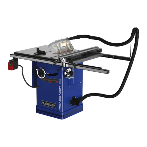
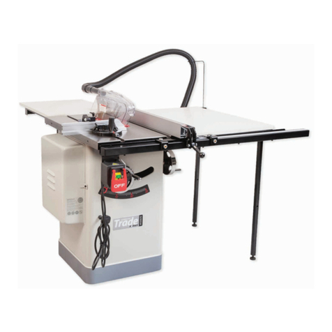
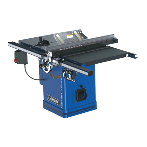
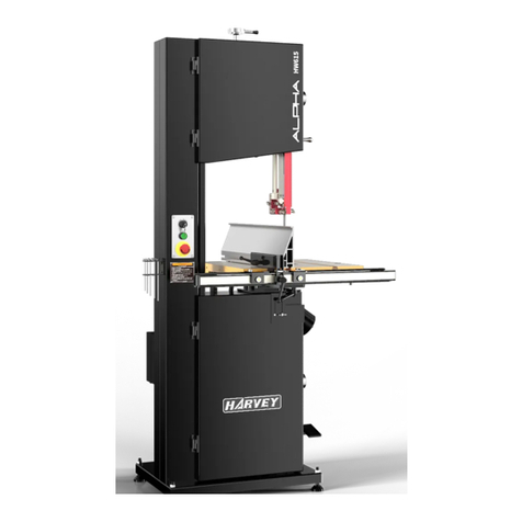
HARVEY HW110LC-36 User manual

Revision A 2020-03-01
INSTRUCTION MANUAL
Original Instructions
10″ Cabinet Table Saw
MODEL:HW110LC-36

READ THIS FIRST!!!
2020-06-28
The following changes were recently made to this machine owing to that the owner’s
manual was printed:
Add "P" to all Model numbers shown in the manual.
Example:
Change the Model number from HW110S-36 to HW110S-36P
Change the Model number from HW110S-52 to HW110S-52P
Change the Model number from HW110LC-36 to HW110LC-36P
Note:
ALPHA series table saws ha e two types:
Titanium-plated cast iron table
------ the Model number dose not contain “P”
Precision ground cast iron table
------ the Model number contains “P”
Important:
Keep this notification with the owner’s manual for future reference.
298001412

Contents
1. Fo ewo d...............................................................................................................................................
2. Wa anty Info mation.........................................................................................................................
3. Machine Desc iption..........................................................................................................................
.................................................................................................................
.................................................................................................................
...................................................................................................................
................................................................................................................................
!.............................................................................................
4. Safety Regulations............................................................................................................................. "
# $% ......................................................................................................."
$ $% $& ' $!................................................................ "
(............................................................................................................................ )
$% ...................................................................................................................... )
5. Installation of the Machine............................................................................................................... *
+........................................................................................................*
(&..................................................................................................................................... *
,......................................................................................................................................-
...................................................................................................................................
6. Adjustment......................................................................................................................................... -
./& ........................................................................................................... -
.&& ' 0 ! 1.........................................................................-
./& 2 *-2 3 $.............................................................................. -
.&& 3& 4 ! 1.......................................................................................
7Ope ations..........................................................................................................................................
" ...................................................................................................................
" 1 3 & ./.................................................................................
" ,&................................................................................................................................
" &........................................................................................................................................
8. Maintenance.......................................................................................................................................
9. T ouble Shooting..............................................................................................................................
10. Exploded View and Pa ts List.....................................................................................................
11. Ce tificates.......................................................................................................................................

1
1. Fo ewo d
'
& '
& & !%
%
&
! 3 %
& !
& & &5 !35
% !%
(
' &
( ! ' !
6 % ' 3&
3 !
3%
2. Wa anty Info mation
Limited Wa anty
! %
P oof of Pu chase
( %
!% 3&
Limited Tool Wa anty
7 ( 3%
& % '% 7
! &
!0%
!% !0% '&
!% %
% % 5 '5
! 5 && 5
'% 8 3 5
( 7
35 ' ' 5 /
% 5
& &
( 3& !%5
! % ' 3
. 95 ! !
% :; 3
!% 3 !(
:; & !%
< , =
9 % ! 5 ! (!
$ ,
5 & !!!7&&3

2
3. Machine Desc iption
3.1 Technical Pa amete s
Fo No th Ame ican Ma ket:
ITEM HW110LC-36
6
7& '
>&?7?@& "-0?A 9 *0?A 9 )0?A:"*99;
-0?A 9 *0?)A:9*);
$! $! % +& ! 3
$ >)
+
% ,5 , $5
@!5 B&5 5 . - @5 B5 @5 .
- @5 - B5 @5 ).
$ -- +
! B0 '' 1 63
1
+9 1 6 -A
(
)
3& 4 ( -A:;
.3' 1 ( --"A0--*A
(
)0
)
.3' 1 4 ( --A0-A
(
0
)
+9 7 6 ?A:-;
1 > -02
.' 6 1 ?)A
(
)"
)
.' $ )- +
.' 1& $ % >'
,& ,
+9 6 , *-2 0?)A:"*;
+9 6 , 2 0?A:;
+9 5 & 1 A:*;
+9 5 > 1 *A:);
'
@& A:)";
+ ' 0 >&?7?( *A 9 A 9 )A:)--9"-9;
6 1! &
' , 1 )*A:)-;
+ #& + #& $ % 0$
+ #& $8 0 7?@& ?A 9 ?)A:*-9*;
1 # 1 # % #>6 $! 1 #
% 0$ @& >!
$8 0?)A 9 0"?)A :) 9 );
& ! ,
6 $8 A:--;

3
Fo Eu opean Ma ket:
ITEM HW110LC-36
6
7& )(&
>&?7?@& "*99
9*)
$! $! % +& ! 3
$ ,
+
% ,5 , $5
@!5 B&5 5 . (75 - B5 @5 - .
$ *-- +
! B0 '' 1 63
1
+9 1 6 -
3& 4 (
.3' 1 ( )0
.3' 1 4 ( 0
+9 7 6 -
1 > -02
.' 6 1 -
.' $ )- +
.' 1& $ % >'
,& ,
+9 6 , *-2 "-
+9 6 , 2 -
+9 5 & 1 *
+9 5 > 1 )
' @& )"
+ ' 0 >&?7?( )--9"-9
+ #& + #& $ % 0$
+ #& $8 0 7?@& *-9*
1 # 1 # % , B $! 1 #
% 0$ @& >!
$8 ) 9 )
& ! ,
6 $8 --

4
Fo Asian Ma ket:
ITEM HW110LC-36
6
7& )(&
>&?7?@& "*99
9*)
$! $! % +& ! 3
$ ,
+
% ,5 , $5
@!5 B&5 5 . (75 - B5 @5 - .
$ *-- +
! B0 '' 1 63
1
+9 1 6 :-A;
3& 4 (
.3' 1 ( )0
.3' 1 4 ( 0
+9 7 6 -
1 > -02
.' 6 1 )"
.' $ )- +
.' 1& $ % >'
,& ,
+9 6 , *-2 "*
+9 6 , 2
+9 5 & 1 *
+9 5 > 1 )
' @& )"
+ ' 0 >&?7?( )--9"-9
+ #& + #& $ % 0$
+ #& $8 0 7?@& *-9*
1 # 1 # % #>6 $! 1 #
% 0$ @& >!
$8 ) 9 )
& ! ,
6 $8 --

5
3.2 Featu es Identification
Fig. 1.
Fig. 1
> 9 7&
+ #&
+ '
1 #
& 9 7&
" ? $!
) + ,3
* 3 . 6 , :%;
- 1 3 @ 7
C '
1 @ 7
,'
NOTE:
Fig.1 is only fo illust ation, and the actual
object shall p evail.
3.3 Optional Equipment
Sliding table
Model: $0--$
Fig. 1-1
Unive sal Ove head Gua d
Model: $0$
Fig. 1-2
Unive sal Mobile Base
Model: +10--
Fig. 1-3

6
3.4 Intended Use
' ! !( &
! ' 93%
!& =
D> ' :&
'5 '5 +6 '5 ;
D$ !
D#% '5 ,'5 B !
' & 3
D6% ' : 5
;
Tools:
D ! ' ' ' '
!( %
D% ' !
3 :,B; & ' :,;
3 :-A;5 ' 8
)" :?)A; -5 ! 9
& ! - !
!
Site of installation / use:
D ' 5
'/ (
9
D 33
'% 9
%
D 33 !
&5
%
&
D ' ! % % ' 5
'% ! !
! &
D 3 &
! % &% &8
% ' '3
D !( ' '% !
3 '% 8
% & ! '
7 ! !% %
& '% & 0&
The machine is p ohibited to be used in a
potentially explosive atmosphe e!
3.5 Requi ements of Elect ical Powe
> & C 0! 3&
+
@ @:(7;
B&:B; ?-B - B
: @8; - @8 -
< . ?) . - .
-
! B? - B?
,
, 1( -.
3 /% &
5 (
% % ! %

7
4. Safety Regulations
4.1 Gene al Safety Inst uctions
1. KNOW YOUR MACHINE.
!E
' 9 >
!
8F
2. GROUND THE MACHINE.
3 5 &&
( F
3. KEEP THE BLADE GUARDS IN PLACE.
4 & !(& 5 % /
&F
4. REMOVE THE ADJUSTING TOOLS
' (& (% /&
! 3 '
& F
5. KEEP THE WORK AREA CLEAN.
, ' 3
+( %
!9 ! '0F
6. AVOID A DANGEROUS ENVIRONMENT
6E !
9 4 !( !
3 & !( F
7. KEEP CHILDREN AWAY.
. 3 ' (
!( F
8. MAKE WORKSHOP CHILD-PROOF.
7 (5 ! '% 3&
(%F
9. USE THE PROPER SPEED.
. ! ' /' !
F
10. USE THE RIGHT MACHINE.
6E
/' ! ! &F
11. WEAR THE PROPER APPAREL.
6 ! &5 &35 (
/!% :&5 !; ' % &
& 3& <0 !
7 3 3&
& & 3 '3
'!F
12. MAINTAIN PROPER FOOTING.
4 & ' 6
30 F
13. MAINTAIN THE MACHINE WITH CARE.
4 '
F
14. DISCONNECT MACHINES.
1 3&5 ! &&
F
15. AVOID ACCIDENTAL STARTING.
+( ! GA
' &&& F
16. USE RECOMMENDED ACCESSORIES.
,
! %
%
8F
17. NEVER STAND ON THE MACHINE.
$ /% 3
6 %
F
18. CHECK FOR DAMAGED PARTS.
1 5 &
& ' %
( % ! %
,(
& 3& 5 '(& 5
&5 % %
. &
& ' % F
19. NEVER LEAVE THE MACHINE RUNNING
UNATTENDED.
! HH 6 !( !%
F
20. ADEQUATE LIGHT
& 8 &&
3 !( F
4.2 Table Saw Safety Inst uctions
1. ALWAYS USE A GUARD.
.!% &5 G0!&A
0!&
! ' % & !(
& &F
2. ALWAYS HOLD THE WORK.
.!% !( % &
&& F
3. ALWAYS USE A PUSHSTICK OR PUSH
BLOCKS.
'( ( ' !
& !(
! % !(
& F
4. NEVER PERFORM UNSAFE OPERATIONS.
<3 % G0A !
& % &
!( .!%
&& & !( F
8
5. STAND TO THE SIDE WHEN FEEDING
MATERIAL.
<3 3 % % '%
! ! 'F
6. USE CAUTION WHEN REACHING FOR
OBJECTS.
<3 ' 3 & !
% F
7. SAFE CROSSCUTTING OPERATIONS.
+3 !% !
&F
8. ENSURE CORRECT FEEDING OF MATERIAL.
!( ' &
F
9. CORRECT USAGE WITH THE FENCE.
<3 0 && ! %
0&F
10. ALWAYS TURN THE POWER TO THE "OFF"
POSITION.
7 & ! '5
!% ! HH F
11. PROVIDE ADEQUATE SUPPORT.
' ! !
& !( F
12. AVOID KICKBACKS.
.3 (('( :!( ! '( ! %;
'% (& ' 5 '% (&
! '5 '% (&
& &5 '%
& !( ' !%
! '5 '% & !(
! ! 3 & &
& & F
13. AVOID AWKWARD OPERATIONS.
.3 !(!
! %
3 & 'F
14. CORRECT SAW BLADE USAGE.
< ! ' ' ! 9
( ! 9
! F
15. CHIP AND DUST.
' 9
9 %F
9 ' !
' & &F
16. CHECK
% ( ' (
! '
-
4.3 Residual Risks
( 8
:& !&
(;F
7 3 & F
.!% ! % & .5
( ( & %F
& 8 '& !
& ! ' !
& F
6 < % 3 ! !
& ! ' 3&F
6 <
& % 3 %
& !(&
4.4 Safety Equipment
7 & ! !(5 1(
' !( &
% . '( ' %
'% ! Fig. 2
!( 0?A :- ;5 %
(5 ! &5
3 % &&
! '
Fig. 2
Fig. 3

9
5. Installation of the Machine
5.1 T anspo tation of Machines
' ! (&
33 3 ' (
% , ' (
& & & ! 3&
.' 0- -
℉
:0
℃
; ' '%
1 9
3 !
While t anspo ting o handling the machine, be
ca eful and let the activity be done by qualified
pe sonnel especially t ained fo this kind of
activity!
While the machine is being loaded o unloaded,
make su e all pe sons a e out of the way so
that no pe son is c ushed by the machine.
Select the p ope t anspo tation device
acco ding to the weight of the machine. Make
su e the lifting capacity of the t anspo tation
device is sufficient fo the weight of the
machine.
' (&
( ' ' '9
Fig. 4 ! 3 ! '
(
Fig. 4
5.2 Unpacking
I ! % (&
3 (&&
% %
3 &5
% , $3 3
$3 (&
' '% &
!5 & & '
Note: If you can't find an item on this list, check
the mounting location on the machine o
examine the packaging mate ials ca efully.
Occasionally we p e-install ce tain components
fo shipping pu poses, o in othe packing.

10
5.3 Contents
The p oduct is packed by fou individual
boxes as follows:
Main machine box contents:
(Fig. 5-1-----Fig. 5-4)
. + ' ! JJJJJJJJ
1 + 3JJJJJJJJJJJ
, > 9 !&JJJJJJJJ
6 9 ' :! ;JJJ
$! 'JJJJJJJJJJJJJ
1 & '%JJJJJJJ
0 :, B ! ' &;
0 :#>6 ! ' &;
@ @ !JJJJJJJJJJJ
>( ('J JJJJJJJJJ
K @9 ! :& ;JJ
4 7 0 ?" JJJJ
> + &&JJJJJJJJJJJJ
+ 6 1 &JJJJJJJJ
< (JJJJJJJJJJ
6 ' JJJJJJJJ
Fig. 5-1
Fig. 5-2
Fig. 5-3
Fig. 5-4
0
0

11
Fence box contents:(Fig. 5-5)
. '%JJJJJJJJJJ
B. JJJJJJJJJJJJJ
Fig. 5-5
Ove a m box contents:(Fig. 5-6)
. 3 JJJJJJJJJJJ
1 9' :& - ;JJJJ
, 9' :& ;JJJJJJ
6 1(JJJJJJJJJJJJJ
Note
:
The assembly contains the co esponding
ha dwa e which is not shown in the figu e, and
can be checked with the exploded view.
Fig. 5-6
Rail box contents:(Fig. 5-7)
. JJJJJJJJJJJJ
1 JJJJJJJJJJJJ
, & 'JJJJ
6 : !;JJJ
Note
:
The assembly contains the co esponding
ha dwa e which is not shown in the figu e, and
can be checked with the exploded view.
Fig. 5-7

12
5.4 Installation
1 '&& '%5 (
!& &&=
FLOOR: +( 3
WORKING CLEARANCES: % &
' 5 % 3
' ! '
OUTLET PLACEMENT: '
& !
9 !
! & 8
DO NOT assemble the machine until you a e
ce tain that the machine is not plugged in and
the powe switch is in the OFF position.
DO NOT connect the machine to the powe
sou ce until you ead and unde stand the enti e
Use Manual.
Pull the switch out of the saw cabinet and
emove the shipping b ace as Fig. 6-1.
Fig. 6-1
5.4.1 Remove the pallet
9 '% +) 9 '
1 &5 (
' 3
3& '
5 ! Fig. 6-2 >
Fig. 6-2
5.4.2 Hand-wheel handle installation
. ! Fig. 7, 0!
' '% & ( ('5
0! .
Fig. 7
5.4.3 Extension wings installation (Fig. 8)
! 9
!& ' &
' 9 !& 0
'
9 !& !=
3 !
'F
9 !& '
& ' &
% ' '%F & &
' ' 5 ! '
% &F
. !& ' '% &
! 3 F
&& ( !
' ! 9 !&
5 (&
9 !& !5 '%
! Fig. 8
Fig. 8
$&
1
@
>( 4'

13
5.4.4 Install the ail & extension table
9 ' '(!
!
1 && 5 ( (
& ! 0
,
! & *
9 ' !
'
Fig. 9
&
' ! Fig. 10
Make su e the cam foot contacts the cam on
the fence lock handle befo e you place the
fence on the ail, othe wise the fence can not
be placed well ( Fig. 10).
If you need to use the fence on the left side of
the blade, emove the knobs (A), as shown in
Fig.10, and move the fence plate and locking
ba to the ight side of the fence body, secu e
them on the left side of the fence body.
Fig. 10
,(
%
(
Fig.11
)
. ! &5 & 5
5
! ' % .
( >L>5 >0>M?H5
! &% & & '!
'5 '5
( !( '& '&
&
Fig. 11
./ %
:Fig.12;
' 05
'5 %
/ !& =
a. Align the the pa allelism between the blade
and T-slot.
1 && %
5 % & '!
' 05 6.2 Aligning
the Table T-slot Pa allel with the Blade.
b. Align the the pa allelism between the fence
and T-slot o blade.
1% /& ! :.;5 % /
'! '5 %
/ (& & 1% /& '
( ! & 5 %
/ % '!
' 1% /& ! :1;5 %
/ &
Fig. 12
By adjusting the suppo t sc ew (not shown) at
the unde neath of the fence, you can aise o
lowe the fence to ensu e that the unde neath
of the fence is pa allel to the table.

14
5.4.5. Post the tape scale use the pointe
window (Fig.13)
@0>! ! !
!! . ! &5 !
!! ' / 3%
!! :.; ! !
!! :1; & I
0/ !! '%
& (' :,; :6;
$
& 5
& ! '5 ( F
'5 (
! '5 G-A
% !!
(
1
)
5 &% ( G-A ' !
5 3 F
% & G-A ( !
( %
,' 7!
& 5 !
& $ & '5 (
G-A ( %
!! :1;5 % 3 5
(' :6;5 0/
!! :1;5 !!
3 G-A ( 5 ('
:6;
! $
& '5 ( G-A (
% !!
:.;5 % 3 5 (' :,;5
0/ !! :.;5
!! 3 G-A ( 5
(' :,;
Fig. 13
5.4.6 Install the switch
(
Fig.14
)
! =
< .
:
& :.;
。
:
& :1;
。
.
:
&:1;
。
'3 E 3 5
'/ 3
! ! &
& ' '% & ! ' !
0 & '
Fig. 14
5.4.7 Install the blade
3 ' F
' !% '
& -NF
. ! Fig. 15, ' (&
'% 5 ' (&
&& ! '5 3 '
& '% & !
$ ! ' '5 (&
!5
' & ' '
&
Fig. 15

15
5.4.8 Install the blade gua d
$ ( (' : Fig. 16)
! && '(
Fig. 16
$ ' & !% !
'(5 ( ('
&& '( (&
&&
Fig.17 :.; ! ' &5 &
>) 5 ' <
. ( Fig.17:1; ! ' &
& , (5
! '
&5 G3. Machine
Desc iptionA
Fig. 17
Check if the saw blade is tightened befo e
ope ating the machine.
Give the sp eade an upwa d tug to ve ify if it is
locked in place.
5.4.9 Ext action system
A dust collection device should be used by the
custome
,
the dust ext action equipment must
be switched on befo e commencing machining.
3 :Fig.18;=
'( :.; ! ! 1
3 '( :1; ! :,;
: ;
, :A; 3 '%
&
Note: & !
0 '
Fig. 18
=
!= "- ,+ :)-- O?;
%& = --
6% = *" + :- ?;
7 = + :) ?; :!
)P;
5.4.10 Moto cove installation
3 '% &
& ( ' !
Fig. 19.
Fig. 19

16
5.4.11 Mite gauge installation
! +#0 +
#& && % &&
!( ! & &
+#0 + #& +
5.4.12 Elect ical installation
Wi ing should only be done by p ofessional
elect icians.
Always make su e the machine is p ope ly
g ounded. All exposed conductive pa ts should
be connected to the p otective g ound ci cuit.
An ove -voltage p otection device should be
p ovided by end use .
The ci cuit b eake shall be installed to supply
elect ic powe to this machine, in o de to
p otect people against elect ical shock due to
incidental contact.
,( 3& % '%
5 ! ! E
5 !
% 3& %
&
' !
&0 5
! &
0 5% ! '
3
Checking:
. & !& 5 5 (
!& =
,( &
!& %
,( 5
& ' &
,( GA '

17
ELECTRICAL DIAGRAM
2 HP, 60 Hz, 115/230 V, 1 PH
(=
& % ! '3
$&0 ! % &= --0- B
+& >)5 & & <0.
230 V Wi ing Diag am
115 V Wi ing Diag am
This manual suits for next models
3
Table of contents
Other HARVEY Saw manuals

HARVEY
HARVEY HW110TC User manual

HARVEY
HARVEY HPS1600E User manual

HARVEY
HARVEY C300-30 User manual

HARVEY
HARVEY C-18VS User manual

HARVEY
HARVEY C14 User manual

HARVEY
HARVEY HW110S-36G User manual

HARVEY
HARVEY C300-30 User manual

HARVEY
HARVEY C200 Series User manual

HARVEY
HARVEY HW615 User manual

HARVEY
HARVEY Axminster AT254LTS User manual