7
EN
1.3. Configurations
The Harvia Fenix control unit consists of different
devices which together allow comprehensive control
over all aspects of sauna bathing. Available device
packages are:
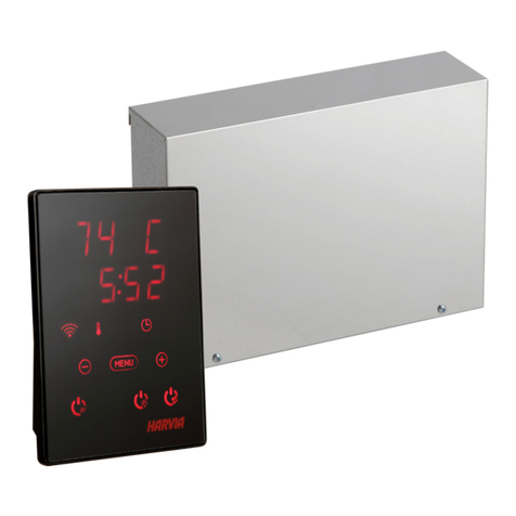
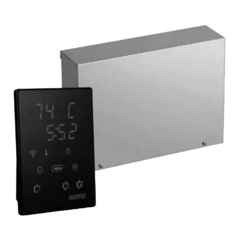
SACF10 wireless control unit for controlling power
units, incl.
Touch screen (wireless control unit)
Recharge stand
Wall-mounting plate for recharge stand
Charger
3 AA rechargeable batteries
Instructions for installation and use.
SACF150 power unit for controlling heater (max.
15 kW), incl.
Power unit SACF150 for heater control
Radio antenna and cable for communication with
wireless control unit
Temperature sensor
Humidity sensor (available as an accessory)
SACF165S power unit for controlling combined
heater/steamer (max. 16,5 kW), incl.
Power unit SACF165S for heater/steamer
control
Radio antenna and cable for communication
with wireless control unit
Temperature sensor
Humidity sensor
SACF100 power unit for controlling colour light,
incl.
Power unit SACF100 for controlling colour light
units max. 2 x 50 W
Cable for connection to power unit SACF150
or SACF165S
2. INSTRUCTIONS FOR USE
Before you switch the heater on check always that
there aren’t any things over the heater or in the near
distance of the heater.
2.1. General
The wireless control unit is equipped with a user-
prompting touch screen and is operated by three
AA rechargeable batteries. The unit comes with a
recharge stand. The recharge stand can be mounted
into the wall or to the table but it must be placed
outside the sauna room. Never take the wireless
control unit to a heated sauna!
The wireless control unit is activated by pressing the
black power switch above the screen. Activation brings
the Start Menu with the function icons to the screen.
Pressing a function icon switches the corresponding
function on or off. Activated functions are indicated
by a dark spot in the corner of relevant function icons
and by ‘active function’ images above the screen.
The touch screen can be operated using a finger
or, for example, the blunt end of a pencil. Avoid
pressing the screen unnecessarily hard!
Clean the touch screen from time to time with a
cloth or mild alcohol wipe.
•
•
•
•
•
•
•
•
•
•
•
•
•
•
•
•
2.1.1. Batteries
The instructions for fitting/changing the batteries can
be found on page 59. The Fenix wireless control unit
comes with NiMh AA HR6 rechargeable batteries,
voltage 1,2 V. The rechargeable batteries can be
replaced with non-rechargeable AA batteries. Note!
Never place the wireless control unit in the recharge
stand when fitted with non-rechargeable batteries. Do
not use rechargeable and non-rechargeable batteries
simultaneously together.
New, unused batteries must be charged uninterruptedly
for 24 hours before use. A complete recharge takes
12 hours. It is recommended to keep the wireless
control unit in the supplied recharge stand when the
unit is not in use – this way the batteries have charge
when the unit is needed again.
Never use a damaged charger or battery. Remove
the damaged battery from the unit. Dispose of the
batteries according to the local regulations (concerning
recycling etc.). Do not place batteries in household
waste. Remove the batteries before disposing of
the unit. Remove the unit from the charger before
fitting/changing batteries.
2.2. Function Menus in the Main Menu and
Function Icons
You can control all functions of your sauna using
the function menus or the function icons.
Function Icons
Light, Fan and Colour Light are activated by pressing
the relevant function icon on the screen.
Sauna ON/OFF
Press the Sauna ON/OFF icon to enable
communication between the power unit and
the wireless control unit. The wireless control
unit now displays information on the conditions
in your sauna, such as temperature and humidity.
Should the connection between the power unit and
the wireless control unit be lost during the bath, the
power unit will nevertheless be able to perform the
programmed functions since all the settings remain
stored in its memory.
Settings (operating time, temperature, humidity
etc.) made in the Sauna ON mode only affect the
current bath.
Settings made in the Sauna OFF mode are default
settings which are stored in the memory of the
wireless control unit.
The Set the Pre-Setting Time icon takes
you directly to the screen where you can
set the pre-setting time.
Pressing the Main Menu icon brings the
function menus to the screen.
Through the Main Menu you can change all the
settings related to your sauna. The function menus
are explained in detail further below.
The pictures shown in this manual are meant as
guidelines only since the screens may vary according
to which features have been acquired and enabled
for use.
Function icons can be added and removed from
the screen. See 2.9.9. ’b) Installed / Enabled
Features’.
