Metal Work Safe Air 70 series User manual

Cod. ECSZZZZ001 ITA_GB - IM02 - 01/2018Metal Work Spa - Via Segni 5 - 25062 Concesio (BS) Italy
ISTRUZIONI ORIGINALI
VALVOLA IN VERSIONE NON ASSERVITA
INGRESSI Elettropilota 0 0 1 1
p porta 1 0 1 0 1
USCITE p porta 2 0 0 0 1
sensore 1 1 1 0
VALVOLA IN VERSIONE ASSERVITA
INGRESSI Elettropilota 0 0 0 0 1 1 1 1
p asservimento 0 0 110011
p porta 1 0 1 010101
USCITE p porta 2 0 0 0 0 0 0 0 1
sensore 1 1 1 1 1 1 0 0
1. Designazione
Valvola di comando per l’interruzione dell’alimentazione e la messa a scarico del ramo di circuito pneumatico
collegato con la porta 2.
2. Descrizione
Valvola 3/2 elettropneumatica monostabile con monitoraggio della spola.
3. Dati tecnici
4. Istruzioni per l’installazione
Per la messa in opera della valvola, seguire i seguenti passi:
- montare la bobina Metal Work per l’azionamento sull’elettropilota e fissarla mediante l’apposita ghiera
(coppia massima 1 Nm);
- collegare i tubi dell’aria alla valvola mediante appositi raccordi pneumatici seguendo la numerazione delle
porte riportata sulla valvola;
- alimentare elettricamente la bobina alla tensione nominale;
- alimentare elettricamente il sensore ad effetto Hall e collegarlo al sistema di diagnostica.
- alimentare pneumaticamente la valvola;
- verificare il corretto funzionamento della valvola e del sensore:
- a bobina diseccitata la porta 1 non è collegata con il circuito pneumatico di valle, la porta 2 è messa in scarico
(porta 3) ed il sensore è in stato ON;
- a bobina eccitata la porta 1 è collegata con la porta 2, ed il sensore è in stato OFF;
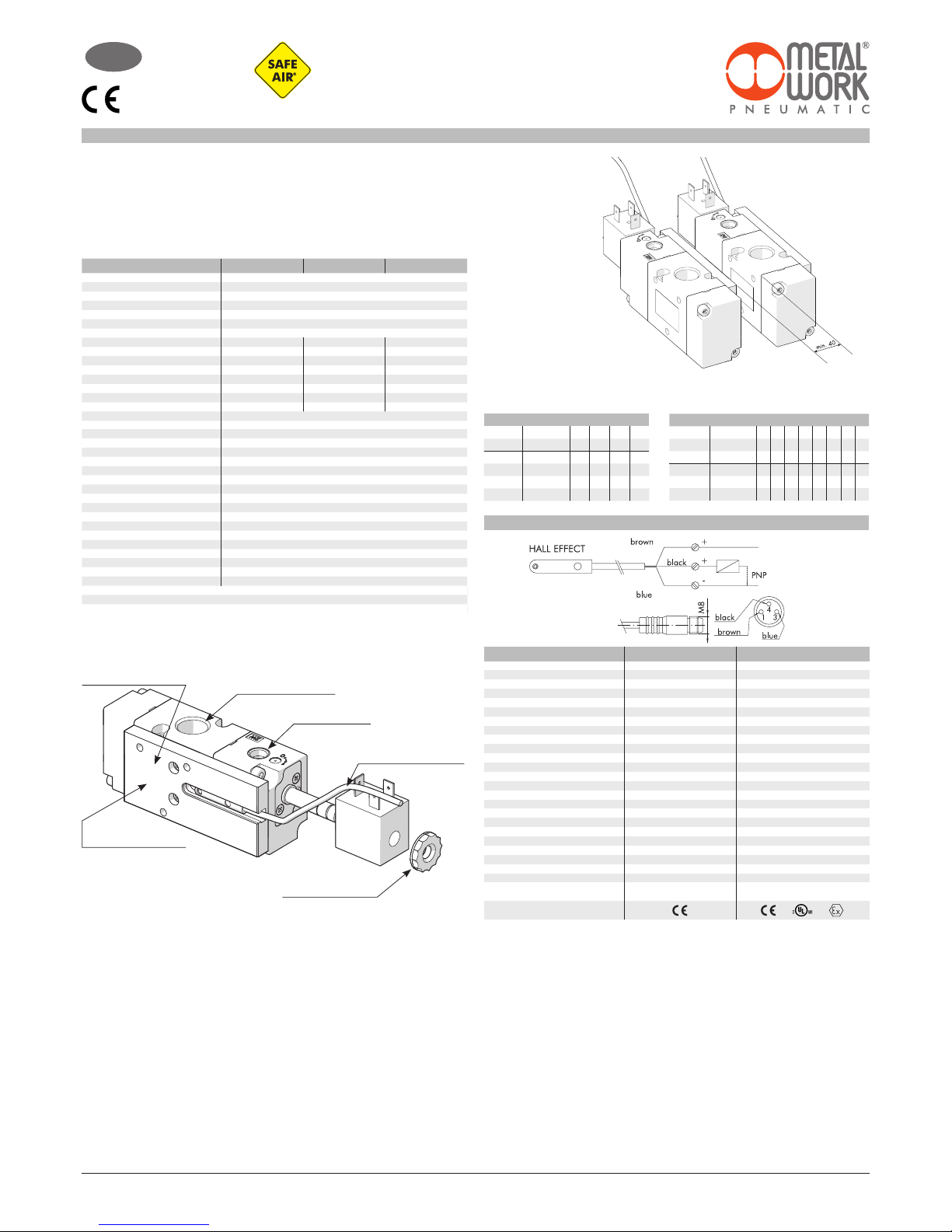
- evitare di montare 2 o più valvole SAFE AIR®in posizioni adiacenti; nel caso di montaggio di valvole
affiancate, la distanza minima tra loro deve essere di 40 mm (vedere fig. 1)
- eventuali masse metalliche ferromagnetiche devono distare almeno 40 mm dal sensore;
- evitare che vi siano campi magnetici di disturbo nell’area prossima ai sensori.
Effettuare i controlli di congruenza secondo le seguenti tabelle che mettono in relazione gli stati di ingressi e uscite
della valvola:
stato 0: alimentazione/segnale assente;
stato 1: alimentazione/segnale presente.
Quando la valvola è in stato sicuro (posizione spola a riposo) il sensore è in stato ON (1).
5. Istruzioni per la manutenzione
Prima di effettuare operazioni di manutenzione si raccomanda di utilizzare i dispositivi di protezione individuali
(DPI) necessari e successivamente di togliere l’alimentazione pneumatica ed elettrica a monte del componente.
Verificare periodicamente che i silenziatori non siano intasati.
Per le operazioni di manutanzione sulla valvola si consiglia di rendere la valvola a Metal Work che provvederà
al corretto rispristino.
6. Avvertenze per i rischi residui
- Il prodotto dev’essere installato da personale tecnico competente
- Verificare che i cavi elettrici non vengano danneggiati durante il funzionamento
- Verificare che i terminali elettrici vengano adeguatamente connessi ad un connettore
- Verificare il corretto inserimento dei tubi prima di alimentare pneumaticamente
- Verificare il corretto collegamento elettrico di bobine e sensori
- Si raccomanda di togliere l’alimentazione elettrica e pneumatica prima di intervenire sul prodotto
- Se la funzione di sicurezza (scarico sicuro) viene utilizzata meno di una volta al mese si consiglia di effettuare
un test di funzionamento con frequenza almeno mensile.
7. Istruzioni per lo smaltimento
Il prodotto deve essere rimosso e smaltito secondo le leggi nazionali, pertinenti in vigore, del paese in cui il
prodotto è stato usato.
SCHEMA ELETTRICO SENSORE
DATI TECNICI SENSORE
Tipo contatto
Interruttore
Tensione di alimentazione (Ub) V
Potenza W
Variazione di tensione
Caduta di tensione V
Consumo mA
Corrente di uscita mA
Frequenza di commutazione Hz
Protezione da corto circuito
Soppressione sovratensione
Protezione all’inversione polarità
EMC
Visualizzazione comunicazione Led
Sensibilità magnetica
Ripetibilità
Grado di protezione (EN 60529)
Resistenza alle vibrazioni e urti
Temperatura di lavoro °C
Materiale capsula sensore
Cavo di connessione 2.5 m/2 m
Cavo di connessione con M8x1
Numero di conduttori
Categoria ATEX
Certificazioni
ATEX
EFFETTO HALL EFFETTO HALL
N.O. N.O.
PNP PNP
10 ÷ 30 DC 18 ÷ 30 DC
3 #1.7
#10% di Ub #10% di Ub
#2 #2.2
#10 #10
#100 #70
#5000 1000
Sì Sì
Sì Sì
Sì Sì
EN 60 947-5-2 EN 60 947-5-2
Giallo Giallo
2.8 mT ± 25% 2.6
#0.1 mT #0.1 (Ub e ta costanti)
IP 67 IP 68, IP 69K
30 g, 11 ms, 10 ÷ 55 Hz, 1 mm 30 g, 11 ms, 10 ÷ 55 Hz, 1 mm
-25 ÷ +75 -20 ÷ +45
PA66 + PA6I/6T PA
PVC; 3 x 0.14 mm
2
PVC; 3 x 0.12 mm
2
Poliuretano; 3 x 0.14 mm
2
-
3 3
- II 3G Ex nA op is IIC T4 Gc X
II 3D EX tc IIIC T135°C Dc IP67 X
MANUALE D’USO PER VALVOLE SERIE 70
SERIE SAFE AIR®
I
1/8” 1/4” 3/8”
Fluido
Aria filtrata (50µm) senza lubrificazione; la lubrificazione, se utilizzata,
deve essere ininterrotta
Funzione valvola
3/2 monostabile
Pressione di funzionamento:
bar
- non asservita
2.5 ÷ 10
- asservita
Vuoto ÷ 10
Pressione minima di asservimento bar
2.5
Temperatura di funzionamento °C
-10 ÷ +60 (-10 ÷ + 45 per versioni Atex)
Conduttanza C Nl/min · bar
121 264 505
Rapporto critico b bar/bar
0.32 0.27 0.32
Portata a 6.3 bar ∆p 0.5 bar
Nl/min
390 820 1600
Portata a 6.3 bar ∆p 1 bar Nl/min
530 1130 2200
TRA/TRR a 6.3 bar ms/ms
15/35 19/45 21/72
Conduttanza C in scarico Nl/min · bar
128 270 491
Rapporto critico b in scarico
bar/bar
0.23 0.29 0.40
Portata in scarico libero a 6.3 bar Nl/min
900 2050 3550
Installazione
In qualsiasi posizione
Montaggio
In linea
Operatore manuale
Monostabile
Lubrificante consigliato
ISO e UNI FD 22
Compatibilità con olii
Vedere www.metalwork.it/ita/materiali_compatibilità.html
Bobine
Lato 30 mm foro ø 8
4 W - 24 VDC
4 VA - 24 VAC, 110 VAC, 220 VA 50/60 Hz
Lato 22 mm foro ø 8
2 W - 12 VDC, 24 VDC
3.5 VA - 24 VAC, 110 VAC, 220 VA 50/60 Hz
Certificate EN 60204.1 e VDE 0580 (*)
Coppia max ghiera bobina Nm
1
Grado di protezione
IP65 con bobina e connettore montati
Livello di rumorosità
Max 78 dBA con scarichi silenziati
B10d
50 x 106cicli
Categoria - ISO EN 13849
2
DC
Low (80 %)
PL - ISO EN 13849
Idonea ad essere utilizzata in circuiti di sicurezza fino a PL=c
* Per evitare inconvenienti nel funzionamento, si consiglia l’utilizzo di accessori Metal Work.
Fig. 1
Montare la bobina sul
pilota e fissarla con la
ghiera (max 1 Nm)
La numerazione delle porte
è riportata sulla valvola
La connessione elettrica del
sensore va eseguita secondo
le indicazioni riportate
Verificare la correttezza
del codice ordinato
Asservimento
(solo per versioni SES)
Collegare i tubi dell’aria
alla valvola mediante
raccordi pneumatici
Metal Work Spa - Via Segni 5 - 25062 Concesio (BS) Italy
ORIGINAL INSTRUCTIONS
VALVE IN NON-INTERLOCKED VERSION
INPUTS solenoid pilot 0 0 1 1
p port 1 0 1 0 1
OUTPUTS p port 2 0 0 0 1
sensor 1 1 1 0
VALVE IN INTERLOCKED VERSION
INPUTS solenoid pilot 0 0 0 0 1 1 1 1
p interlock 0 0 110011
p port 1 0 1 010101
OUTPUTS p port 2 0 0 0 0 0 0 0 1
sensor 1 1 1 1 1 1 0 0
sensor 1 1 1 1 1 1 0 0
1. Designation
Control valve for cutting off the air supply and relieving the air circuit connected to port 2.
2. Description
3/2 elettropneumatic monostable valve with spool monitoring.
3. Technical data
4. Installation instructions
Proceed as follows to install the valve:
- mount the Metal Work coil for operating the solenoid pilot and tighten the locking nut (maximum torque 1 Nm);
- connect the air tubes to the valve using pneumatic fittings, following the port numbering shown on the valve;
- energise the coil at the rated voltage;
- energise the Hall sensor and connect it to the diagnostic system.
- actuate the valve with compressed air;
- check operation of the valve and sensor:
- with the coil de-energised, port 1 is not connected with the pneumatic circuit of downstream, port 2 discharges
(port 3) and the sensor is ON;
- with the coil energised, port 1 is connected to port 2 and the sensor is OFF.
- do not mount 2 or more SAFE AIR®valves in adjacent positions; in case of assembly of valves placed side by
side, the minimum distance between them must be 40 mm (look at fig. 1)
- any ferromagnetic masses must be at least 40 mm from the sensor;
- prevent magnetic fields from creating disturbance in the sensor area.
Perform consistency checks based on the following tables, which relate the valve input and output statuses:
0 = de-energised / signal absent;
1 = energised / signal present.
When the valve in a safe status (spool in home position), the sensor is ON (1).
5. Maintenance instructions
Before carrying out any maintenance operations it is recommended to use the personal protective equipment ,
and then to remember to switch off the electricity and compressed air supplies.
Check the silencers regularly for blockage.
For maintenance operations, it is advisable to return the valve to Metal Work for the necessary repairs.
6. Instructions to prevent residual risks
- The valve must be installed by a qualified technician
- Make sure the power cables do not get damaged during operation
- Make sure the power terminals are properly connected
- Check that the pipes are inserted properly before activating the air supply
- Check that the coils and sensors are correctly wired
- Cut off the power and the air supply prior to maintenance interventions
- If the safety function (safe relief) is used less than once a month, it is advisable to conduct a monthly function test
7. Disposal instructions
The product must be dismantled and disposed of in accordance with the regulations in force in the country in which
the product is used.
TECHNICAL DATA SENSOR
Type of contact
Switch
Supply voltage (Ub) V
Power W
Voltage variation
Voltage drop V
Input current mA
Output current mA
Switching frequency Hz
Short-circuit protection
Over-voltage suppression
Polarity inversion protection
EMC
LED display
Magnetic sensitivity
Repeatability
Degree of protection (EN 60529)
Vibration and shock resistance
Temperature range °C
Sensor capsule material
2.5 m/2 m connecting cable
Connecting cable with M8x1
Wire NO.
Category ATEX
Certifications
ATEX
EFFECT HALL EFFECT HALL
N.O. N.O.
PNP PNP
from
10 to 30 DC
from
18 to 30 DC
3 #1.7
#10% of Ub #10% of Ub
#2 #2.2
#10 #10
#100 #70
#5000 1000
Yes Yes
Yes Yes
Yes Yes
EN 60 947-5-2 EN 60 947-5-2
Yellow Yellow
2.8 mT ± 25% 2.6
#0.1 mT #0.1 (Ub and ta fixed)
IP 67 IP 68, IP 69K
30 g, 11 ms,
from
10 to 55 Hz, 1 mm 30 g, 11 ms,
from
10 to 55 Hz, 1 mm
from
-25 to +75
from
-20 to +45
PA66 + PA6I/6T PA
PVC; 3 x 0,14 mm
2
PVC; 3 x 0,12 mm
2
Polyurethane; 3 x 0,14 mm
2
-
3 3
- II 3G Ex nA op is IIC T4 Gc X
II 3D EX tc IIIC T135°C Dc IP67 X
WIRING DIAGRAM SENSOR
OPERATING INSTRUCTIONS
FOR SERIE 70 VALVES SERIE SAFE AIR®
GB
1/8” 1/4” 3/8”
Fluid
Filtered unlubricated air (50µm); lubrication, if used, must be continuous
Operation
3/2 monostable
Operating pressure:
bar
- non-assisted
2.5 ÷ 10
- pilot-assisted
Vuoto ÷ 10
Minimum pilot pressure bar
2.5
Operating temperature range °C
-10 ÷ +60 (-10 ÷ + 45 for Atex version)
Conductance C Nl/min · bar
121 264 505
Critical ratio b bar/bar
0.32 0.27 0.32
Flow rate at 6.3 bar ∆p 0.5 bar
Nl/min
390 820 1600
Flow rate at 6.3 bar ∆p 1 bar Nl/min
530 1130 2200
TRA/TRR at 6.3 bar ms/ms
15/35 19/45 21/72
Conductance C on relief Nl/min · bar
128 270 491
Critical ratio b on relief
bar/bar
0.23 0.29 0.40
Flow rate on free exhaust 6.3 bar Nl/min
900 2050 3550
Installation
any position
Assembly
In line
Manual actuator
Monostable
Recommended lubricant
ISO and UNI FD 22
Compatibility with oils
See webpage www.metalwork.it/eng/materiali_compatibilita.html
Coils
30 mm side, ø 8 hole
4 W - 24 VDC
4 VA - 24 VAC, 110 VAC, 220 VA 50/60 Hz
22 mm side, ø 8 hole
2 W - 12 VDC, 24 VDC
3.5 VA - 24 VAC, 110 VAC, 220 VA 50/60 Hz
Certified EN 60204.1 and VDE 0580 (*)
Max coil ring nut torque Nm
1
Class of protection
IP65 with coil and connector mounted
Noise level
Max. 78 dBA with silenced relief
B10d
50 x 106cicli
Category - ISO EN 13849
2
DC
Low (80 %)
PL - ISO EN 13849
Suitable for use in safety circuits up to PL=c
* To avoid malfunctions, we recommend using Metal Work accessories.
Fig. 1
Mount the coil on the
pilot and tighten the
locking nut (max 1 Nm)
The port number is shown
on valve
The electrical connection
of the sensor must be as
indicated
Check the order code is
correct
Pilot (only SES versions)
Connect the air tubes to
the valve using pneumatic
fittings
Table of contents
Languages:
Other Metal Work Control Unit manuals

Metal Work
Metal Work EB 80 User manual

Metal Work
Metal Work EB 80 User manual

Metal Work
Metal Work Safe Air 70 series User manual

Metal Work
Metal Work Multimach User manual

Metal Work
Metal Work HDM User manual

Metal Work
Metal Work EB 80 User manual

Metal Work
Metal Work EB 80 User manual

Metal Work
Metal Work HDM series User manual

Metal Work
Metal Work HDM User manual

Metal Work
Metal Work EB 80 User manual


