hatch X-RAY FS04 Guide
Page 1 of 34
Document Number
SMN-002381-0-20
Document Revision
Rev- A
Release Date
Publication Language
English
Hatch X-Ray pursues a policy of continual product development. Although
every effort is made to produce up-to-date product documentation, this
publication should not be regarded as an infallible guide to current
specifications. We reserve the right to make changes without prior notice.

THIS PAGE LEFT BLANK INTENTIONALLY
Page 2 of 34
1 Introduction
1.1 About HATCH X-RAY
•The HATCH X-RAY High Frequency Intraoral X-ray has been engineered and manufactured to
provide many years of reliable service. The system houses two microprocessors, one for
control/supervisory functions and another to provide the user/machine interface. The technology
incorporates feedback circuits to ensure accuracy and reproducibility of X-ray output for dental
diagnostic radiography. The HATCH X-RAY will create radiographs of excellent quality, performing
equally well using digital or film-based imaging media.
•The High Frequency Intraoral X-ray is hereafter referred to as HATCH X-RAY in this manual. Review and
follow the guidelines included in both this manual and the User’s Manual supplied with the equipment
to thoroughly become familiar with the installation as well as operating and safety procedures. This
will ensure that your HATCH X-RAY gives you the highest level of service.
1.2 Scope of This Manual
•This manual provides necessary information for installation/setup for all HATCH X-RAY models
listed by Table 1-1. This manual or the User’s Manual supplied with the equipment is not to be used as
a replacement for training in radiography. The User’s Manual provides instructions for the day-to-day
operation and maintenance of the HATCH X-RAY. This manual is intended for the installation and
performance of the unit. It contains safety tips to prevent unwanted X-ray exposures, physical injury
and proper functioning of the equipment. The manual also covers debugging of anticipated problems
and their correction. Location and meaning of the various labels are provided.
•Review and follow the procedures included in this Installation Manual to ensure precision installation
of the HATCH X-RAY allowing the accuracy and reproducibility of X-ray output.
Table 1-1 HATCH X-RAY Models
1.3 Symbols in this Manual
Page 3 of 34
Description
Part No
Hatch X-Ray X-RAY, FS04,Wall Mount, 15” Extension arm
303-002381-0
Hatch X-Ray X-RAY, FS04,Wall Mount, 24” Extension arm
303-002382-0
Hatch X-Ray X-RAY, FS04,Wall Mount, 33” Extension arm
303-002383-0
Caution Symbol
Used in this manual to alert users to important instructions that require caution.
Since the instructions following this symbol relate to personnel safety, they must
be read carefully to avoid any problems or injuries.
Note! Symbol
This symbol points to an important detail / tip in
the operation of the unit. Read carefully to avoid
any problems

2 Safety and Precautions
2.1 General Safety Tips
•Installation of the HATCH X-RAY must be done only by an authorized service engineer. Consult the
factory or dealer as necessary.
•Make sure that the HATCH X-RAY is assembled and installed in compliance with all applicable laws and
recommendations concerning electrical safety.
•The unit contains and generates high voltages. Only a trained service personnel should attempt to open
the protective plastic covers or repair the unit.
•This X-ray equipment may be dangerous to the patient and the operator unless safe exposure factors and
operating instructions are observed. Follow proper X-ray radiation safety rules.
•Follow instructions specified in this manual when carrying out exposures during installation.
•Do not use non prescribed exposures.
•Make sure that only the operator and the patient are present in the treatment room during radiation
exposure procedure.
•Always be at a distance of more than 2 meters away from the Tube head while carrying out exposures.
•Exercise caution when operating and installing the mechanical suspension arm. The arm is spring
loaded and can bounce out if proper installation procedures are not followed.
•Where complete safeguarding of the equipment is not possible, due care must be taken to ensure that no
part of your body or clothing can be trapped or injured by any part of the equipment. In particular, make
sure that fingers are not caught or pinched during scissor arm movement.
•Ensure proper electrical grounding. A bad grounding can be dangerous for the operator and can generate
malfunctioning of the device.
•Turn Off and Remove All Power Before Performing Any Service. Wait for at least 2 minutes after
mains power off before opening and accessing the covers. During this time, remove the mains plug
from the wall socket or turn off circuit breaker.
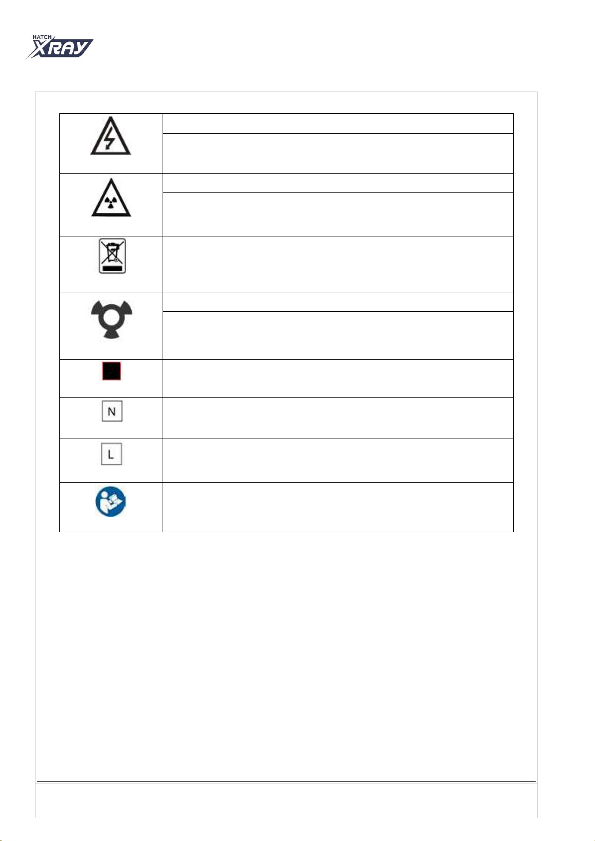
2.2 Safety Symbols
•The following safety related symbols are found on the equipment.
Page 4 of 34
Scissor arm can open out during installation of the unit which may cause injury
to persons / patient standing close to the equipment Always make sure to lock
the movement of the scissor arm in folded condition
Caution Symbol
This symbol indicates the user to be cautious and refer to the user manual
for safe operating instructions.
Protective Earth Ground
Mains Earth Ground is required for continued protection against shock
hazards.
Type of Insulation
Class 1, Type B Insulation. Protection against electric shock
(UL60601-1:2003). Requires protective Earth Connection.
2.3 Labels on Production
•Refer to User Manual for the list and location of each label used on the equipment.
Page 5 of 34
High Voltage
Dangerous voltages present.
Caution: X-Ray
X-Ray Source Assembly / Tube-head capable of generating X-Rays. This
X-Ray unit may be dangerous to patient & operators unless safe exposure
factors and operating instructions are observed.
WEEE Symbol
Indicates that the unit conforms with WEEE Directive 2002/96/EC and must
be disposed of only at the appropriate facilities for recovery and recycling.
X-Ray Emission Status
X-Ray Emission /ON
Focal Spot
Mains Neutral Connection
Mains Line Connection
Follow Instructions for use

3Product Overview
3.1 HATCH X-RAY System Components
Table 3-1 HATCH X-RAY System components
Page 6 of 34
Description
Part No.
Hatch X-Ray X-RAY, FS04,Wall Mount, 15” Extension arm
303-002381-0
Hatch X-Ray X-RAY, FS04,Wall Mount, 24” Extension arm
303-002382-0
Hatch X-Ray X-RAY, FS04,Wall Mount, 33” Extension arm
303-002383-0
15 Inches Long
24 Inches Long
33 Inches Long
Note: The Tube-head is shipped attached to the Scissor Arm
Scissor Arm Assembly (includes cables)
70kVp 8mA Tube-head Assembly
Control Console with Cable
Base Unit Assembly
Exposure switch with cable
Template for Wall Plate Installations
Template for Remote Wall Plate Installations
Remote Keypad Console (Optional)
Remote Doorbell Switch (Optional)
Extension Arm Assembly
(one only)

4Pre-Installation Requirements
4.1 Tools and Consumable Material
Given below is the consolidated list of the Service Tools & Consumables which are required
for executing the procedure in this manual.
4.2Site Preparation
Site Survey
Make sure that the wall for mounting is strong enough for the installation and meet the support load
requirements of paragraph 4.3.
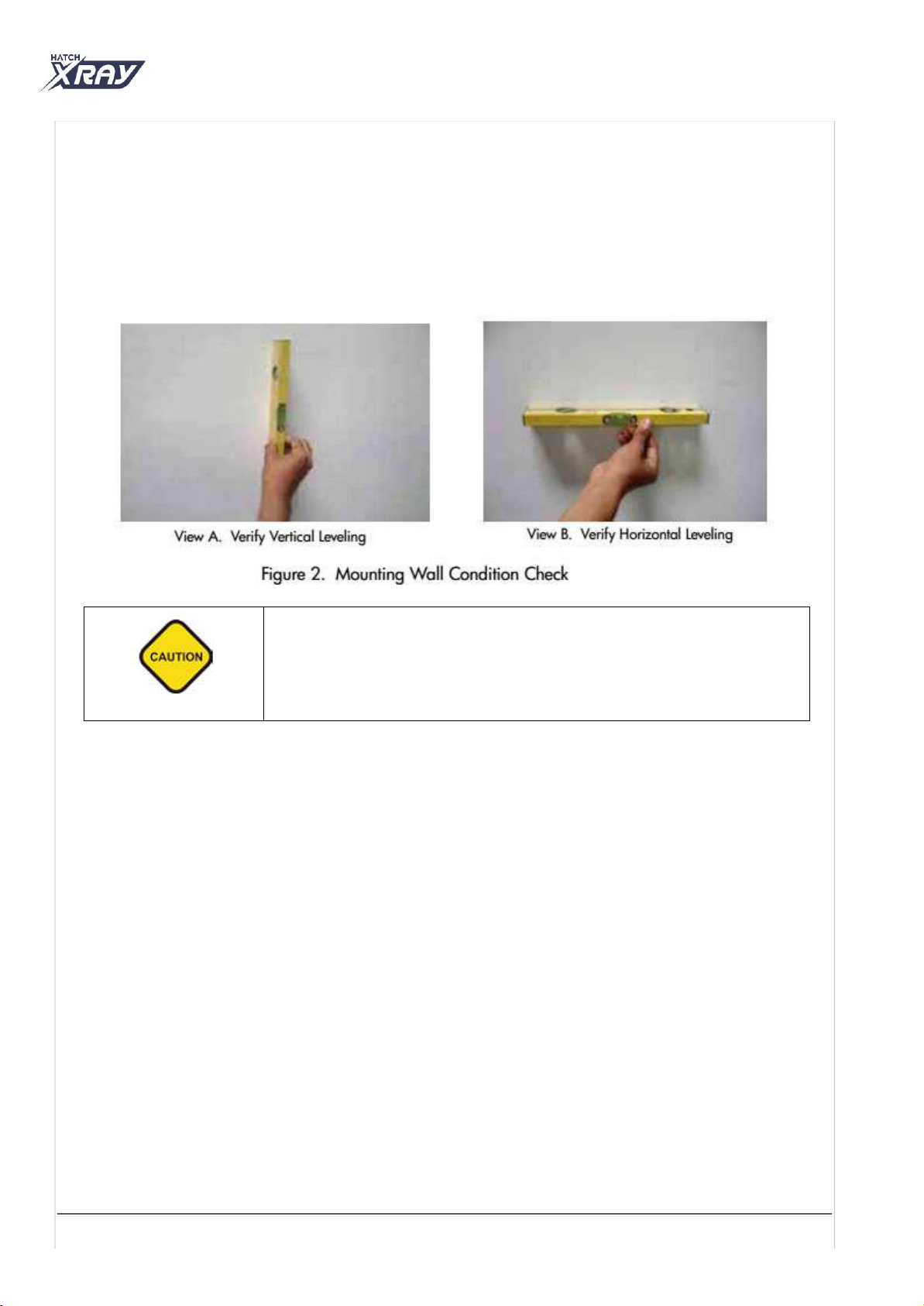
Make sure wall is levelled in both vertical and horizontal direction using a level indicator as shown
in Figures below. If the wall is not level, unit to be installed using additional wall plate(optional)
and to be levelled by inserting shims as required between wall plate and base unit plate.
Make sure there shall be no electrical wiring conduits running around the area to be drilled for the
installation bolts.
Make sure that Base Unit to be mounted on the wall at a height of 40" for two stud mounting and
32" for single stud mounting from the floor (Above finished floor). However this can change based
on site condition without affecting the functionality of the system.
Make sure the location allows sufficient space for movement of the arms in the extended condition.
Make sure that the location allows the Dental X-ray Unit to be used with ease for all possible
imaging procedures on the patient with respect to the patient chair location.
Site Environment Requirements
The unit is designed for indoor usage.
It should not be subjected to direct sunlight for any extended duration.
Mount it away from sources of liquid ingress.
If The X-ray unit is stored below 50° F, time must be allowed for X-ray unit to reach room
temperature before connecting it to the mains voltage.
Page 7 of 34
Tools
Hand-held Power Drill
Long nose Pliers w/Cutter / Tweezers
5/32” or 4mm wood drill bit
Jeweler's Screwdrivers (Phillips & flat)
Screwdrivers (Phillips & flat)
ESD Wrist Wrap
Crimping tool with Dies 2035
Digital Multi-meter
Soldering Iron
Lead Cup for Blocking Cone
Measuring Tape
1/2” Drive Socket Wrench with 17mm socket
A Long Spirit Level with 3 indications
L type Allen key set
Nylon Tube with Hook wire for routing wire(cable)
Circlip Plier 90 degree
T type Allen key set
Nut Driver 5.5mm, 5mm nut Driver or Spanne
Measuring Tape (3 mtr)
Consumable Material
Consumable Material
Insulation Tape (if required for Trouble shooting)
Non-insulated Ferrule/Dowel Stud for wiring
Solder (Lead) (if required for Trouble shooting)
Electrical Outlets & Requirements
The mains outlet should have a ground connection. Grounding of the electrical system must be
checked before connecting Hatch X-Ray.
Additional wiring required for the site must done by a qualified electrician. All wiring should
conform to requirements provided by the User manual and in accordance with local codes.
The mains outlet should be capable of supplying 16A (110V) of current. It shall have fuse protection
or provided with a circuit breaker of 20A (110V).
It is recommended to have an ELCB (Earth Leakage Circuit Breaker) for protection against earth leakage
4.3 Support Load Requirements
The HATCH X-RAY is designed to mount on either a single 4” x 4” wood stud or two 2” x 4” wood studs that
are spaced 16-inch on center and drywall or equivalent wall finish.
The wall support and mounting hardware for the HATCH X-RAY must withstand 150(68 kgs) pounds shear load,
and a withdrawal force at each of the mounting bolts of 800(363 kgs) pounds.
The wall fabrication and attachments to the building structure must be capable of withstanding a load
moment of 1100(499kgs) pounds.
4.4 Electrical Power Requirements
The system requires a three-wire power supply. The three-wires provide two power lines (L) Line and
(N) Neutral and a Ground.
Line Voltage: 100-110V / 230-240VAC +/- 10% Exposure Current: 11A @100 V /4A @230V
Standby Current: 0.25 Amp Max. Main Fuse Rating: 10 Amp
Page 8 of 34
The scissor arm with tube head attached is shipped tied close Do not remove
the locking system holding the scissor arm in folded position until directed
during installation Always make sure to hold both arms of the assembly
simultaneously while lifting or moving the Scissor Arm
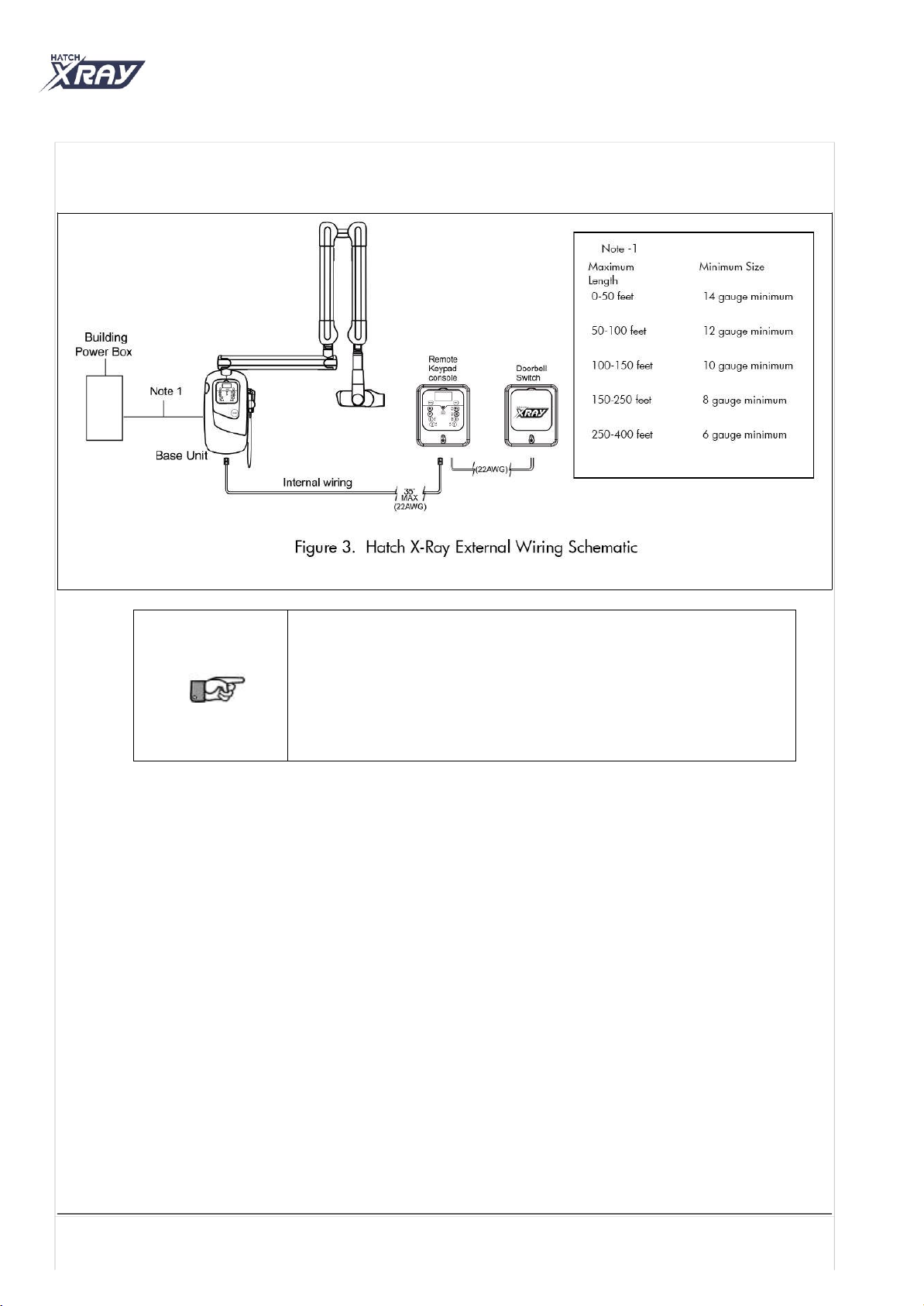
4.5 Wiring Length and Gauge Requirements
Maximum length of wire and minimum gauge wire (AWG) from the power panel box to the Base Unit.
Page 9 of 34
When using Remote console configurations recommended cable length (for
RJ45 (8P8C), RJ11 (6P4C) z and 3 wire) is 35' maximum.
No crossover in any of the RJ45 and RJ11 connector cables used for remote
console configuration (i.e,.1 to 1 connections).
Use CAT6 cable for all applicable configurations where RJ45 is used.
Recommemded specification for the wires used in all 3-wire configuration and
wires used between two remote console is “Belden cable PVC 3X22 AWG(Part
#Belden 88463)or equivalent” .
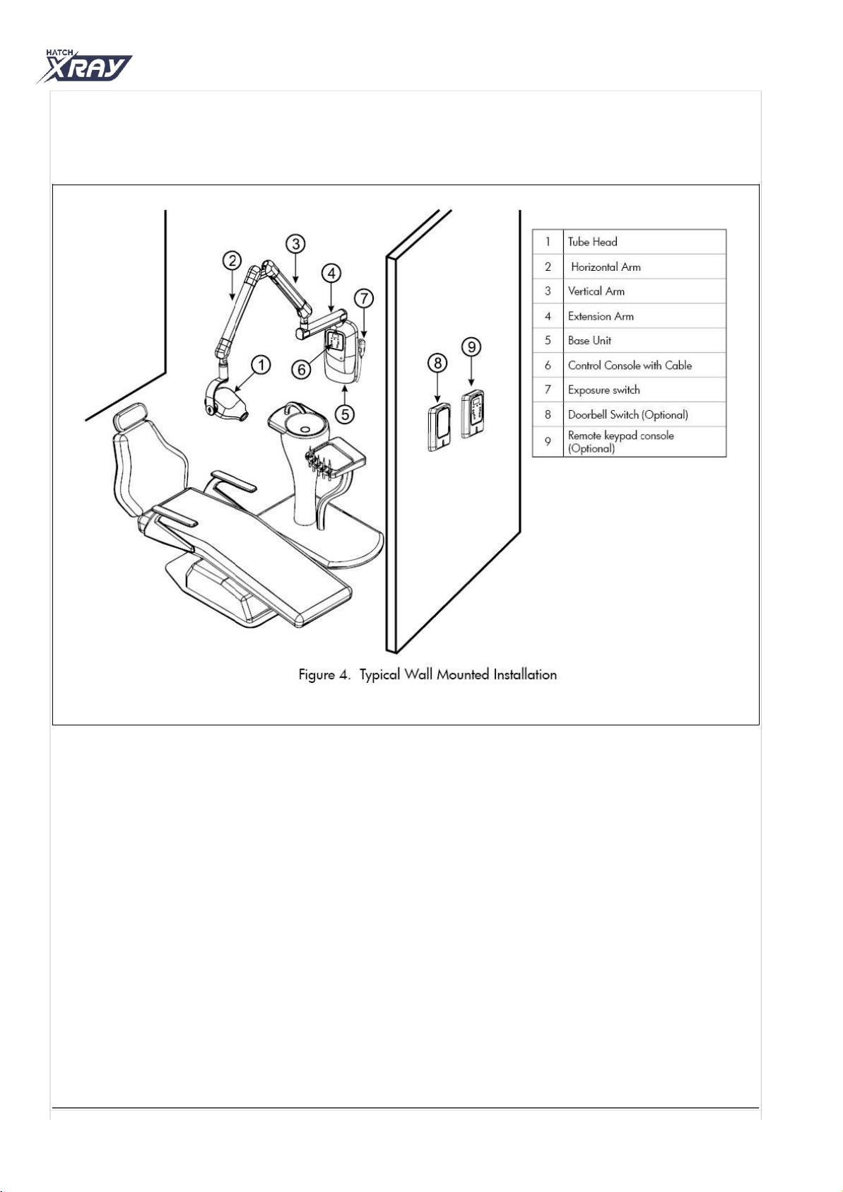
4.6 Included System Components
•As shown by Figure 4 below, the major components and accessories included with a wall mounted Hatch
X-Ray. Verify that all listed items were received for the unit. If any item is missing, take appropriate action
to get the missing parts.
5Installation of HATCH X-RAY
Installation Procedure Summary
This section provides the instructions necessary to install the Wall Mounted HATCH X-RAY.
Install the HATCH X-RAY wall mount by performing the tasks summarized below and provided
by the following pages.
�Unpacking.
�Base Unit Installation using Wall Mounting Options.
1. 16 Inch on Center Mount Installation/Two stud mounting.
2. Single stud Mounting (4 x 4 inch post).
3. Base unit mounting with Optional wall plate(If applicable).
�Input wiring.
�Installing the Straight Arm onto the Base Unit.
�Installing the Scissor Arm with Tube Head onto the Straight Arm.
�Connecting the Scissor-arm cables.
�Remote console Configuration (If applicable).
�Performing the operational check procedures.
Page 10 of 34
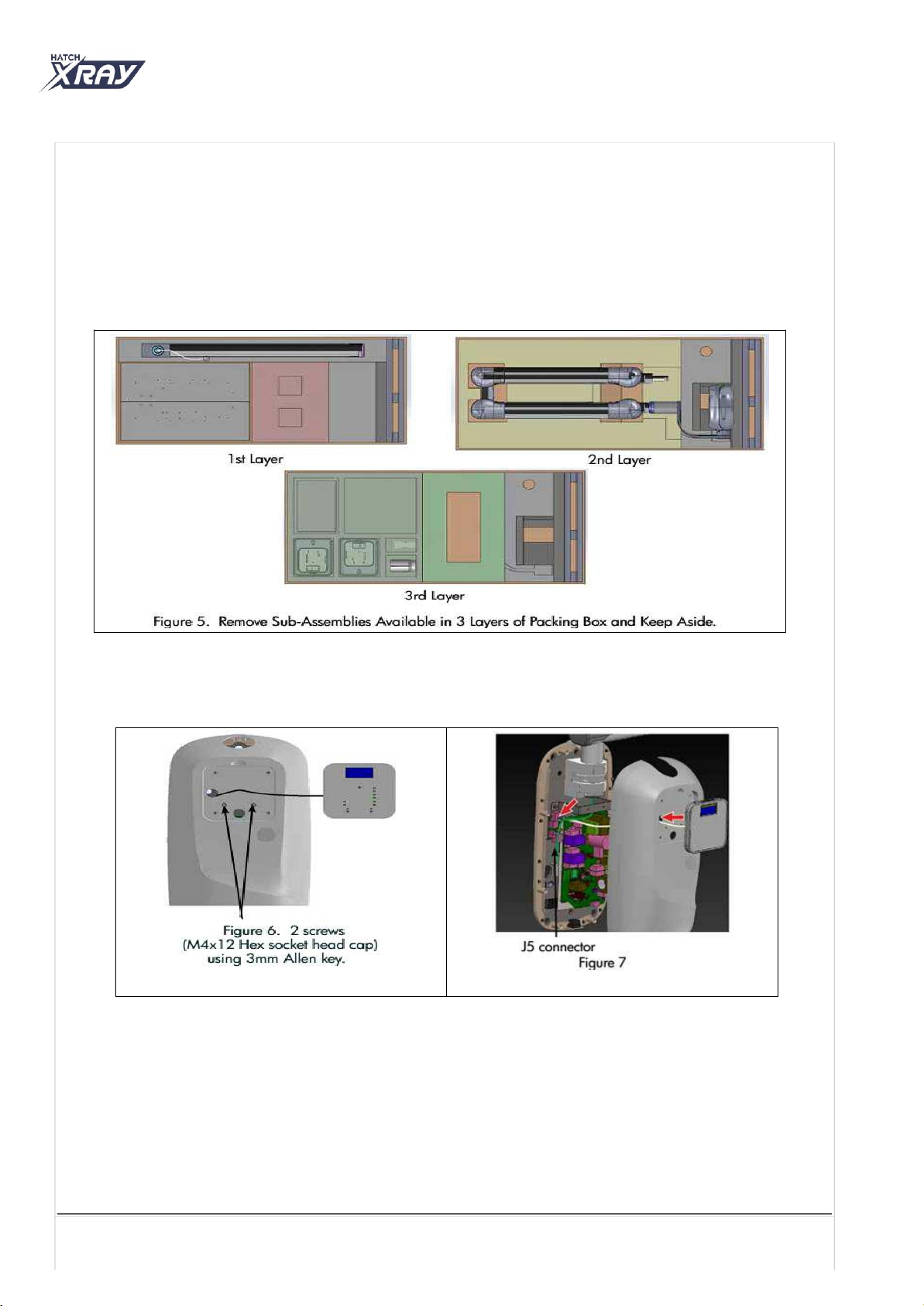
5.1 Unpacking
•HATCH X-RAY is shipped in a corrugated box with each sub assembly packed in designated location
positioned by foams.
•Unpack the X-ray system and inspect each component for physical damage such as scratched panels, damaged
connectors etc. In case of any damages observed, appropriate action has to be taken to get the replacement parts
before starting the Installation. Open the box by cutting the straps and keep all the parts outside on a cushioned
surface as shown in Figure 5 .
•Pull out the console assembly from the base unit cover and remove 2 Screws (M4x12 Hex socket head cap) using
3 mm Allen key as shown in Figure 6 .
•Lift the base unit cover slowly and disconnect the Console cable (if connected) from J5 connector of Console
extension board-internal located beside the power board as shown in Figure 7 and keep it separately.
5.2 Base Unit Mounting
•HATCH X-RAY Wall mount Unit comes packed in Single stud mounting configuration. In order to convert the unit for
Two stud installation configurations follow the procedure provided below.
Page 11 of 34
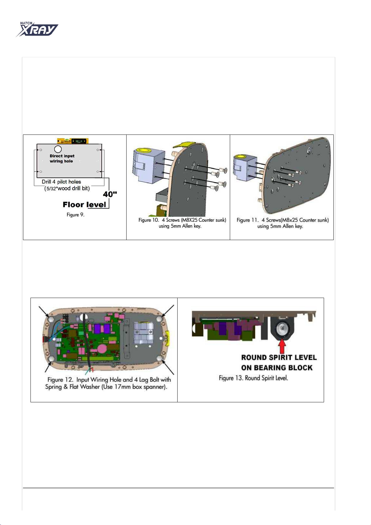
5.2.1 Two Stud Mounting / 16” On Center Mounting
Install the HATCH X-RAY using the 16-inch on center mounting configuration method by following procedure
below.
•Locate the 2 wood studs (2“x4“ inch) to mount the base unit plate and mark template holes and drill 5/32” holes
to depth of 3½ “ as shown in Figure 9 .
•Install power and control wiring, following all local codes for electrical work.
•Remove the bearing block from the base unit plate by removing 4 screws (M8x25-Counter sunk) using 5 mm Allen
key as shown in Figure 10 .
•Install the bearing block to the base unit plate aligning to the other 4 holes using 4 screws (M8x25-Counter sunk)
using 5 mm Allen key as shown in Figure 11 .
•Take the base unit plate and route the input wires and communication cables (if remote console is used) through
the hole provided on the base unit plate as shown in Figure 12 .
•Install the base unit plate on two 1½” x 3½” studs aligning to the 4 drilled holes using 4 lag bolts (M10x80) with
M10 plain washers at the 4 corner holes as shown in Figure 12 (Do not tighten fully).
•Check and confirm the level of the base unit by placing the round spirit level on the bearing block and then
tightening the bolts using 17 mm box spanner as shown in Figure 13 .
•Continue with the procedure, section “5.3 Procedure for Input wiring:”
5.2.2 Single Stud Mount Installation
•Locate the wood stud (4”x4”) to mount the base unit plate and mark template holes as shown in Figure 14 (Ensure
that the template is level on the wall using spirit level). Drill 5/32” pilot holes to the depth of 3½”.
•Install power and control wiring, following all local codes for electrical work.
•On the base unit plate, disconnect the RJ-25(6P6C) cable from the J4 connector on the power board and disconnect
the line and neutral wires from J5 connector on the power board using screw driver as shown in Figure 15.
•Remove the base unit cover clamp by removing 2 screws (M3x6-Hex socket head cap) using 2.5mm Allen key as
shown in Figure 16 .
Page 12 of 34

•Remove 1 screw (M3x6-Hex socket head cap) with plain washer used for locking the power board using 2.5mm
Allen key as shown in Figure 17 and swing the power board assembly towards right.
•Carefully lift the base unit and route the input power cable and communication cables (if remote console is used
from the hole provided for wiring as shown in Figure 18 .
•Mount the base unit plate on the wall using 4 lag bolts (M10x80) with M10 plain washer at mounting holes
using 17 mm box spanner as shown in Figure 18 (Do not tighten fully).
•Verify the level by placing round spirit level on the bearing block and then tighten the 4 lag bolts using 17mm
box spanner as shown in Figure 19 .
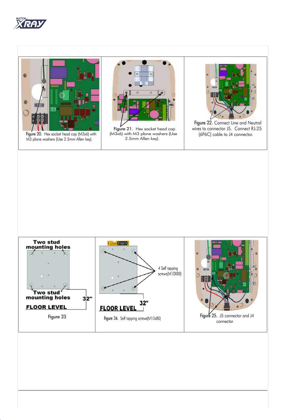
•Swing the power board assembly close and lock with 1 screw (M3x6 Hex socket head cap) with M3 plain washer
using 2.5mm Allen key as shown in Figure 20 .
•Install the “base unit cover clamp” with 2 screws (M3x6 Hex socket head cap) with M3 plain washers using
2.5mm Allen key as shown in Figure 21 .
•Refer to Figure 22 and using a screwdriver make the following connections.
1) Connect back the RJ-25(6P6C) cable to the J4 connector
2) Connect the line and neutral wires coming from switch to the J5 connector on the power board.
Note: Refer to 5.3 / 5.4 Procedure for Input Wiring for additional wire connections.
Page 13 of 34
5.2.3 Base Unit Mounting with Optional Wall Plate (Applicable only for Two Stud Mounting)
Note: Optional wall plate can be used for ease of input cables routing if hole on the wall is not at the required location.
•Locate the 2 wood studs (2” x 4” studs) to mount the additional wall plate.
•Mark template holes and drill 5/32” diameter holes to depth of 3½” as shown in Figure 23.
•Drill the direct wiring hole ( >1.5”diameter).
•Install power and control wiring, following all local codes for electrical work
•Remove the four rubber plugs from the corner screw holes of the wall plate and set aside for reuse.
•If the external console is used, route the input wires and communication cables through the hole provided for
wiring.
•Secure the plate onto the wood wall studs by using 4 Lag bolts (M10×80) along with M10 plain washers at the
drilled locations using 17mm Box spanner (Do not tighten fully) as shown in Figure 24 .
•Check and confirm the level using spirit level and then tighten the bolts.
•Install the four rubber plugs to the corner screw holes of the wall plate.
•Take the base unit assembly and disconnect the RJ-25(6P6C) cable from the J4 connector on the power board and
disconnect the line & neutral wires from J5 connector on the power board using screw driver as shown in Figure 25
•Remove1 screw (M3x6 Hex socket head cap) with plain washer used for locking the power board using 2.5mm
Allen key as shown in Figure 26 and swing the power board assembly.
•Remove the base unit cover clamp by removing 2 screws (M3x6 Hex socket head cap) using 2.5mm Allen key
as shown in Figure 27.
•Install the base unit plate assembly on the optional wall plate with 6 bolts (M10x20 Hex head) along with M10
plain and spring washers using 17mm box spanner as shown in Figure 28.
Page 14 of 34

•Secure the “base unit cover clamp” with 2 screws (M3x6 Hex socket head cap) with M3 plain washers
using 2.5mm Allen key as shown in Figure 27.
•Continue with the procedure “5.3 Procedure for Input wiring:” towards right.
5.3 Procedure For Input Wiring (Direct Wiring)
•Remove the cable clamp (located near the input wiring hole) by removing 2 screws (M3x6 Hex socket head cap)
using 2.5 mm Allen key as shown in Figure 29 .
•Strip the insulation on each input wire for a length of approximately 5 mm.
•Using the Paladin Crimping Tool with Dies 2035 or equivalent as shown in Figure 30 , crimp the three wire
terminal to the Line, Neutral and Ground wires of the Input power cable from wall.
•Using screwdriver install the line and neutral wires coming from the wall to the terminal block such that Line
wire matches with label “L”, Neutral wire matches with label “N” as shown in Figure 31.
•Connect the Ground wire on the power board plate near grounding label with screw (M3x6 Hex socket head
cap) using 2.5 mm Allen key as shown in Figure 31.
•Secure the input cable with the input cable holding clamp by routing the input cable through the clamp and
tightening with 2 screws (M3x6 Hex socket head cap) using 2.5 mm Allen key as shown in Figure 31.
Page 15 of 34


•Connect back the RJ-25(6P6C) cable to the J4connector and line & neutral wires coming from switch to the J5
connector on the power board using screw driver as shown in Figure- 37.
•Remove the cable clamp(located near the input wiring hole) by removing 2 screws (M3x6 Hex socket head
cap) using 2.5 mm Allen key as shown in Figure- 38.
•Using screw driver fix the line and neutral wires coming from behind the Power board to the terminal block
such that Line wire matches with label “L”, Neutral wire matches with label “N” as shown in Figure- 39.
•Fix the Earth wire on the power board plate near earthing label with screw(M3x6 Hex socket head cap)using
2.5 mm Allen key as shown in Figure- 39.
•Fix back the cable clamp routing the input cable through the clamp with 2 screws(M3x6 Hex socket head cap)
using 2.5 mm Allen key as shown in Figure- 39.
5.5 Extension Arm Installation (ForAll Variants)
•Remove the M6 stopper screw from the Extension arm guide rod using 5mm Allen key as shown in Figure 40 .
•Refer to Figure 41 and loosen the 2 no’s of M4x20 Hex socket head cap screws of the bearing block using a 3mm
Allen key.
•Route the guidewire and ground wire through the slot of the bearing block and mount the Extension arm on the base
unit bearing block and install the M6 stopper screw to the Extension arm guide rod using 5mm Allen key as
shown in Figure 42.
•Check and confirm the level of the extension-arm using spirit level by rotating the arm to all directions.
•Tighten the 2 no’s of M4x20 Hex socket head cap screws at the location shown in Figure 43 using 3mm Allen key
ensuring the smooth movement of the Extension arm.
•Route the grounding wire of the Extension arm on the rear side of the power board assembly and fix it at the
grounding label location on the power board plate using 2.5mm allen key as shown in Figure 39 .
Page 17 of 34
Figure- 37
Figure- 38
Figure- 39
Figure 40
Figure 41
Figure 42
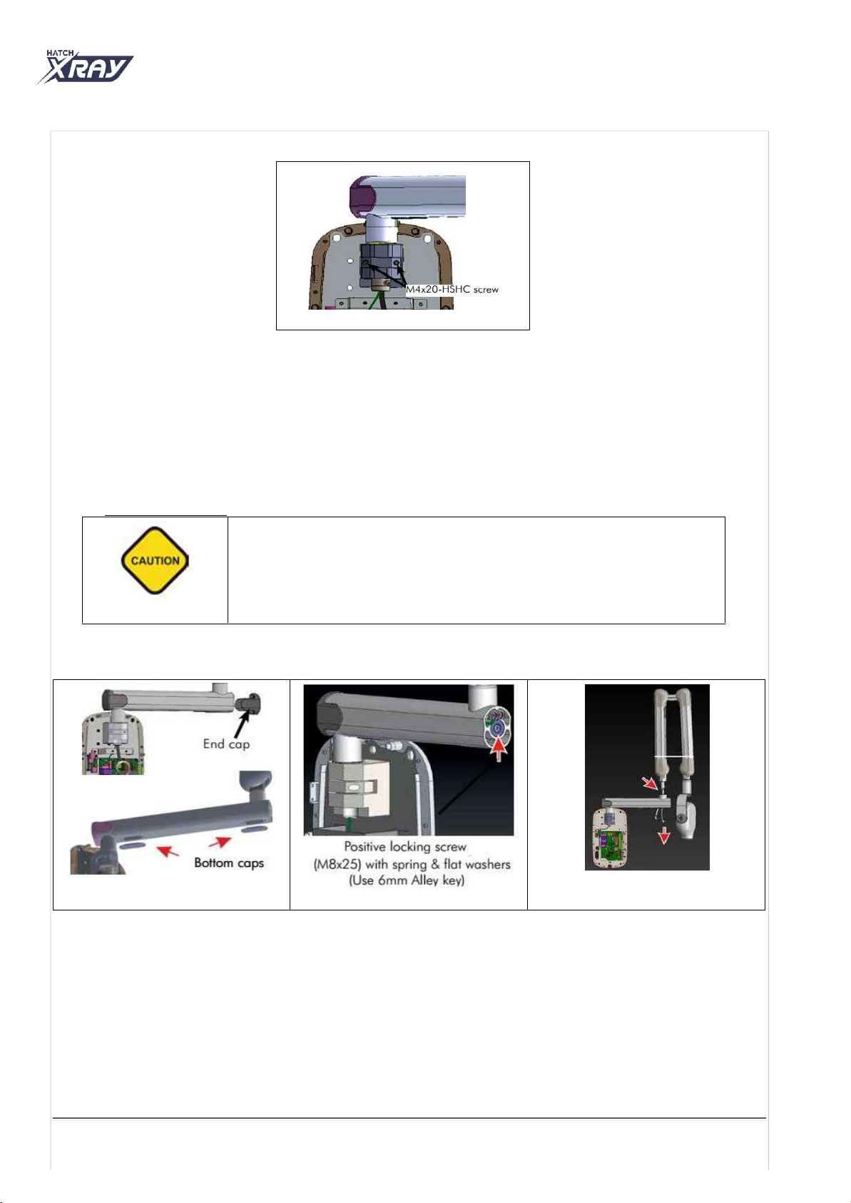
Figure 43
5.6 ScissorArm Installation
•Using a screwdriver remove the M3x6 Counter sunk screw securing the end cap to the Extension arm. Remove the
end cap as shown in Figure 44.
•Remove the 2 bottom caps of the Extension arm by removing the two M3x6 Counter sunk screws securing each cap
on the Extension arm. Remove the each bottom cap as shown in Figure 44.
•Remove the Positive locking screw (M8x25) along with M8 plain and spring washers using 6 mm Allen key as
shown in Figure 45.
•Route scissor arm cables through the coupler on top of the Extension arm.
•Using the guide wire for routing wires, slide the scissor arm with attached tube head into the Extension arm as
shown in Figure 46.
•Cut the cable tie holding the scissor arm.
•Install the Positive locking screw (M8x25) along with M8 plain and spring washers using a 6mm Allen key
as shown in Figure 45.
5.7 ScissorArm Cable Connections
•Lock the scissor arm cables to the end of the guide wire with magic twister provided with cables as shown in Figure
47 .
Note: Do not pull the guide wire and it is to be used only for aligning and routing cables.
•Push the scissor arm cables from the free end of the Extension arm till it comes inside the base unit.
•Separate the guide wire from scissor arm cables and remove the magic twister and insulation tape from the cables
gently without damaging the crimping connections as shown in Figure 48.
•Using a 2.5 mm Allen key, connect the GND wires of both scissor arm cables to the Power Board ground point
screw (M3x6 Hex socket head cap) as shown in Figure 48.
Page 18 of 34
The scissor arm with tube head attached is shipped tied close. Remove the securing
cable tie only when directed during installation. The scissor arm can spring open
causing injury.
Always make sure to hold both arms of the assembly simultaneously while lifting or
moving the scissor arm.
Figure 44
Figure 45
Figure 46
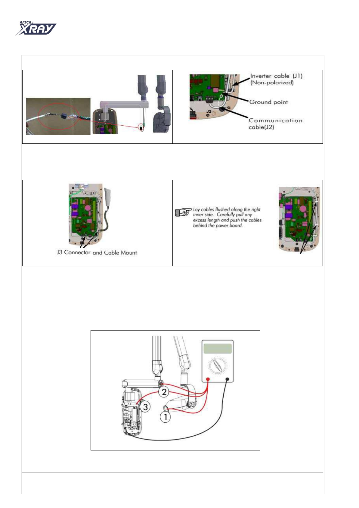
•Connect the exposure switch cable to the J3 connector on the power board. Leave 3 coils and tie the exposure
switch cable along with scissor-arm cables at the bottom cable mount using cable tie as shown in Figure 49.
•Lock the scissor-arm cables on the cable mounts available beside the power board using cable ties at the
locations shown in Figure 50.
5.8 Ground Connection Test
Using a Multimeter, check the continuity between the following points as shown in Figure 51.
•Between Ground point of power board and Tube Head inner Cone metal part.
•Between Ground point of power board and Extension arm end.
•Between Ground point of power board and Base Unit Wall mounting plate.
If any of the test fails then check the Ground connections inside Base Unit & Tube Head for Cable fault.
Figure 51
Page 19 of 34
Figure 47
Figure 48
Figure 49
Figure 50
5.9 Remote Console Installation (Optional)
•Take the remote console template from packing box and tape it at the desired location on the wall stud.
•Use the Spirit level and make sure that the template is level.
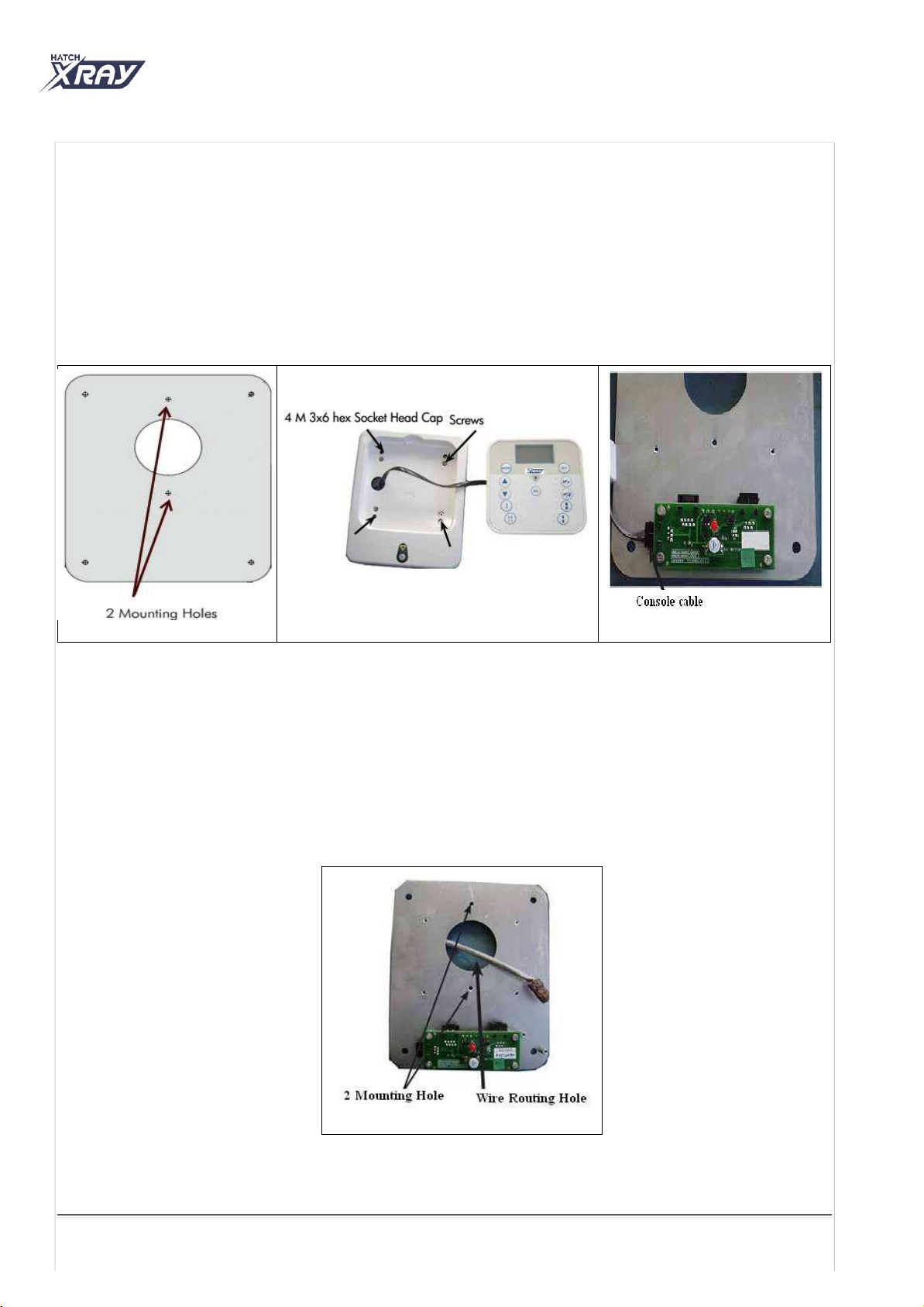
•Mark the locations for the 2 mounting holes on the template.
•Drill the holes marked using 9/64-inch drill bit to the depth of 0.84” as shown in Figure 52.
•Take the remote console assembly and pull out the console from the slot.
•Remove the plastic cover by removing 4 ( M3x6 Hex socket head cap) screws with M3 plain washers using a 2.5
mm Allen key as shown in Figure 53 .
•As shown in Figure 54 , lift the cover along with console assembly and disconnect the console cable from the
board. Keep the parts aside for reuse.
•Take the remote console and route the remote console communication cable through the hole provided on the
plate as shown in Figure 55.
•Secure the remote console plate on the stud by inserting the 2 no’s of 6.3 x 32mm Self Tap Wood Screw at the
locations shown in Figure 55. Tighten using an 8 mm box spanner.
•Connect the remote console communication cable as per the connections shown below in 5.9 HATCH X-RAY
Console Configurations.
•Follow the same steps for the second console as above if double doorbell switch is used.
•Connect the external console cable to J8 connector and close the cover of the remote console by installing 4 (M3x6
Hex socket head cap) screws using a 2.5 mm Allen key as shown in Figure 53.
•Secure the remote keypad console in the slot of the cover.
Figure 55
Page 20 of 34
Figure 52
Figure 53
Figure 54
This manual suits for next models
3
Table of contents


