HATRIA FUSION BATT YXC1 Instruction Manual
FUSION BATT
CODE YXC1
Circuit version “SB39”
Flush when moving away
ELECTRONIC FLUSHING SYSTEM
FOR URINAL POD
ALKALINE BATTERIES (3X1,5V) OPERATED
FUSION BATT
VT 04/10
Rev. 2
A
ENG
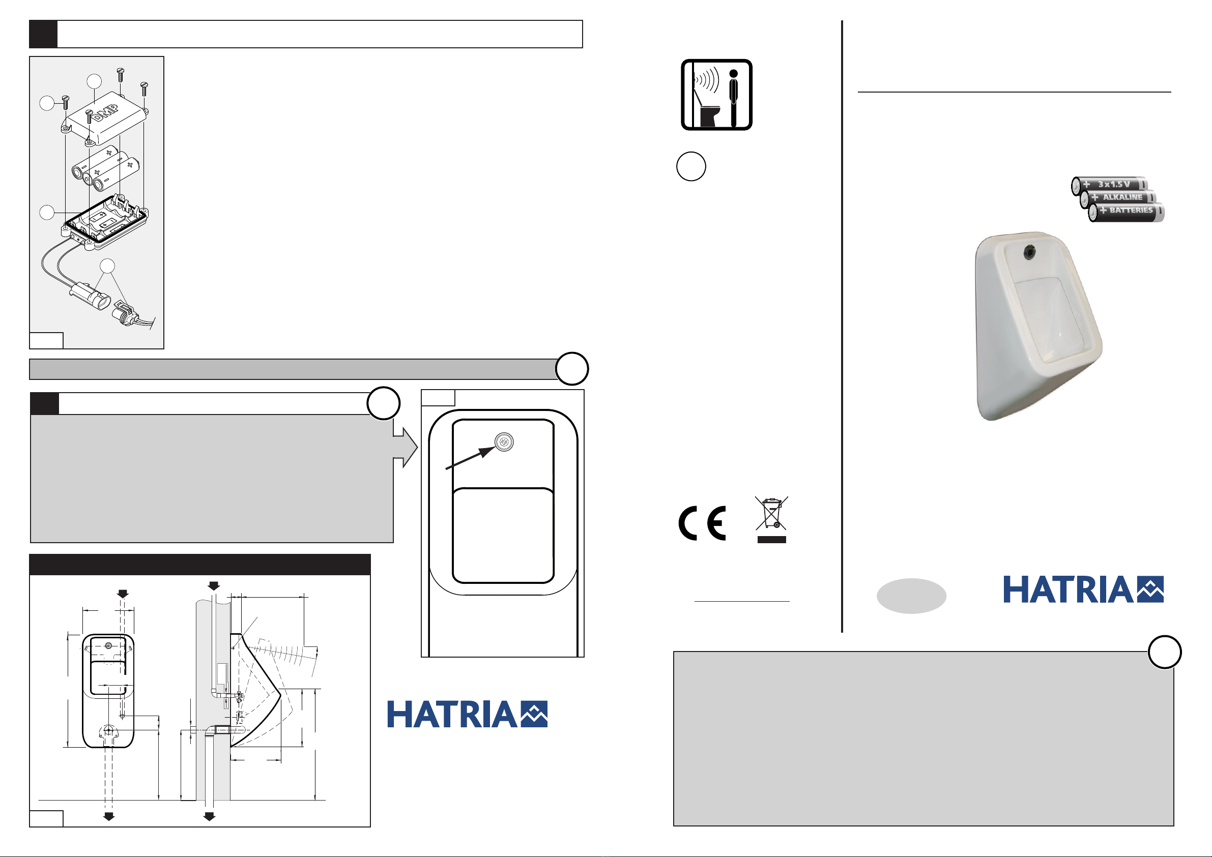
CLEANING RULES
5
Th urinal pod s nsor’s boady is in STAINLESS STEEL AISI 316
th r for v ry r sisitant to corrosiv products. How v r it is
r comm nd d, for cl aning th urinal pod to us warm wat r
and do not us abrasiv d t rg nts. To avoid damaging th
s nsors do not us corrosiv products or m tallic, abrasiv
spong s.
OTHERWISE THE WARRANTY WILL BE INVALID !
FIG.
• BEFORE USING THE PRODUCT READ CAREFULLY THE INSTALLATION INSTRUCTION AS WELL AS
THE ENCLOSED DRILLING DIAGRAM FOR MOUNTING THE CERAMIC URINAL POD TO THE WALL.
• HATRIA DECLINES ALL LIABILITY FOR DAMAGE OR INJURY CAUSED BY THE FAILURE TO FOLLOW ALL
THE INSTRUCTIONS PROVIDED IN THIS INSTRUCTION BOOKLET.
• THE PRODUCT'S OVERALL RELIABILITY AND DURATION ARE ENSURED BY CORRECTLY PERFORMING
ALL THE OPERATIONS PROVIDED IN THIS BOOKLET.
• KEEP THIS BOOKLET IN A SAFE PLACE.
• THIS PRODUCT MUST BE INSTALLED BY PROFESSIONALLY QUALIFIED PERSONNEL.
• THE PLUMBING SYSTEMS CONNECTED TO THE EQUIPMENT MUST COMPLY WITH THE STANDARDS
IN FORCE.
!
!
INSTRUCTIONS FOR CHECKING AND REPLACING BATTERIES
4
CHECK
The electronic flushing system FUSION BATT is fed by 3 low-cost and readily available
batteries • The batteries used are of alkaline type of 1.5 V-Size AA • The operation voltage is 4,5
Vdc (3 x 1.5V). • The batteries durability is approx. 4 years for 200 operations per day • Do not
us r charg abl batt ri s • Purchase only batteries that have a stamped expiry date which is
a minimum of 4 years after the date of your purchase. This will ensure a long durability of batteries
and a correct use of your electronic flushing system FUSION BATT. • Do not replace the
batteries with wet or damp hands, in damp places or with damp tools. • Wat r must n v r b
insid th batt ry pack otherwise batteries will be immediately discharged!
REPLACEMENT
When the red LED (2) (Fig. 2) starts to flash at regular intervals of 2 sec., it means that batteries
are being used up. However they will keep a residual period of operation which varies according
to the number of operations. To replace the batteries effect the following operations :
A) Disconnect (16) the battery pack and the circuit.
B) Remove the cover (19) of the battery pack by unscrewing 4 screws (20). Take the batteries out.
C) Insert the new batteries in the battery pack by paying attention to the polarity +and -.
D) Remount the cover of the battery pack paying attention at the gasket (21) in its seat.
E) At this point it may be reset the connection (16) between the battery pack and the circuit.
19
20
21
16
FIG. 7
OUT
ø40
405
360
650
305
325
405
685
10°
G1/2
MAX
FISSAGGI
IN
53
80
OVERALL DIMENSIONS
mm
fasteners
FIG. 9
IT IS RECOMMENDED TO EFFECT THE DISPOSAL OF THE USED UP BATTERIES ACCORDING TO THE NORMS IN FORCE
!
INSTALLATION AND MAINTENANCE
INSTRUCTIONS
AND DRILLING DIAGRAM FOR
MOUNTING THE URINAL POD TO WALL
Cod. 0935.ENG
Hatria S.p.A
tel. +39 059 3 4556 • fax +39 059 3 4212
[email protected] • www.hatria.com
HATRIA thank you for choosing the
FUSION BATT
electronic system for urinal pod. To obtain the optimum performance,
please read and follow carefully the instructions contained in this leaflet.
INSTALLATION AND MAINTENANCE INSTRUCTIONS
1
IMPORTANT - BEFORE INSTALLING THE ELECTRONIC SYSTEM
FUSION BATT
min.
180 cm
B for installing th l ctronic flushing syst m
FUSION BATT
,
v rify that th ntranc door to toil t or th front wall (FIG. 6) do
not int rf r with th s nsors b am which is s t to 30 cm.
Th r for , it is r comm nd d to install th
FUSION BATT
in locals
having th m asur m nts shown in FIG. 6.
FIG. 6
ATTENTION - BEFORE INSTALLING
OPERATION AND NOTE FOR ADJUSTING THE SENSORS BEAM
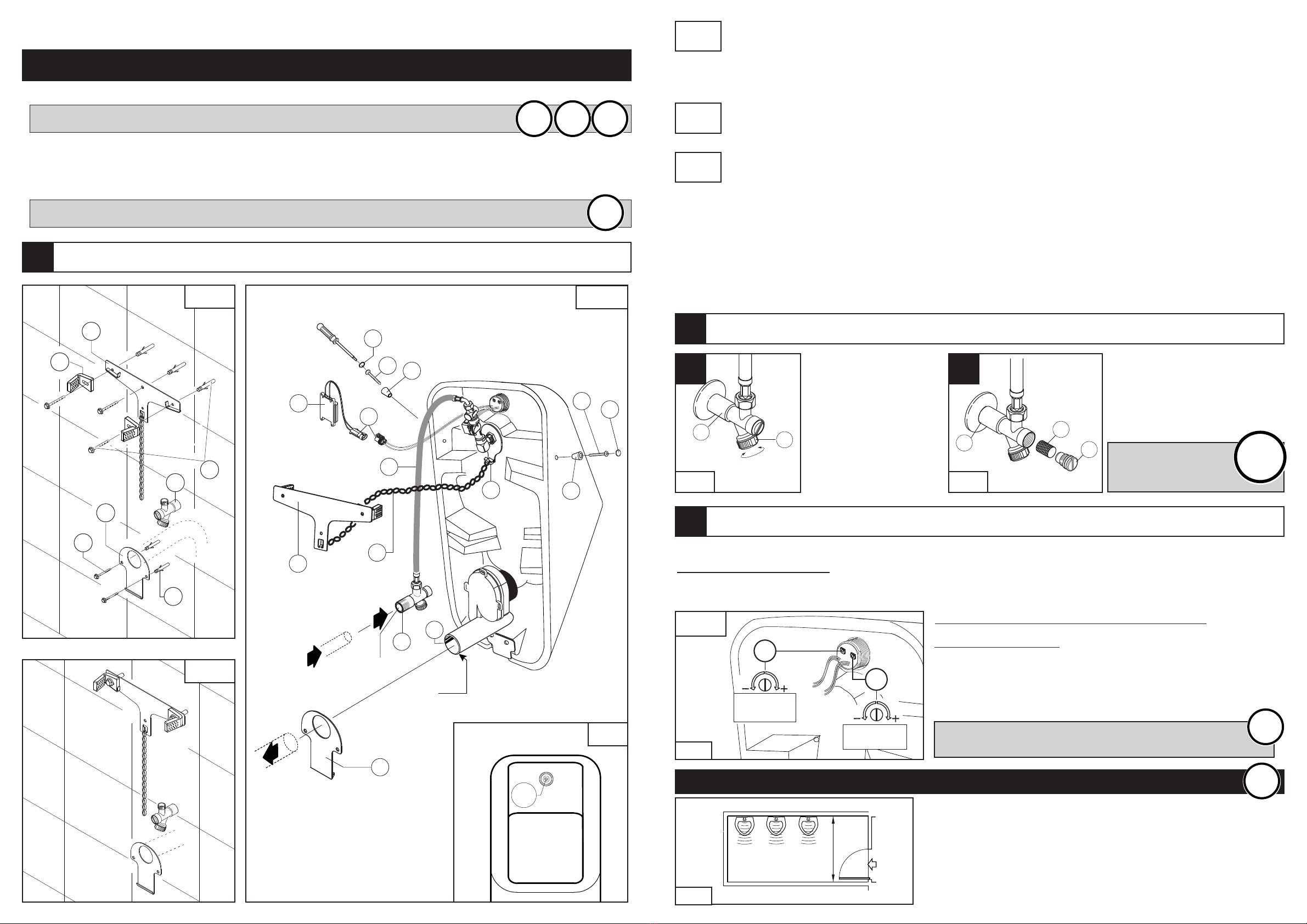
3
Fix the drilling diagram to the wall in order to centre the holes. Ensur that th c ntr of th drainag
hol is at approx. 40,5 cm from th floor according to fig. 9. Fix to the wall the upper plate (1)
through the parts (1 ) and the supplied 3 nogs and 3 screws (2). Then mount the lower plate (17)
using 2 nogs and 2 screws (2).
Screw the shut-off tap (3) to the ½ G plumbing outlet on the wall.
The installation should be according to the drawing Fig. 1/B
Insert the drainage siphon (4) in the wall; ensure that the pipe is perfectly watertight. Hook FUSION BATT
to the lower plate (17) and carefully connect the siphon black rubber ring (4); hook the chain (5) to the
upper plate (1).
Connect the flexible hose ( ) to the shut-off valve (3) then open the water flow on the shutt-off tap (3)
(see Fig. 3 an Fig. 4). Fasten the connectors (16) between the battery pack (22) and the electronic circuit
through a screw driver. Close FUSION BATT and screw the screws (7) together with the plastic
spacers (15). Be careful not to break the screws. Cover the screws with the supplied covers (14).
The circuit is activated when the user is in front of the sensor; wh n h has b n d t ct d a r d LED
(LR) is on in th circuit (fig. 2). Onc th us r has l ft, th flush will start and continu s for an
adjustabl tim (s par. 3 fig. 5).
Th circuit will activat an automatic flush ach 12 hours
for approx. 30 s c. aft r th last op ration.
!
!
•Wat r f d pip s must b of minimum 1/2 G
and a min. wat r flow of 15/20 litr s p r minut at 3 bar.
1)
B for conn cting th wat r supply nsur that th pip work is blown cl an of any d bris which
could damag th l ctrovalv s
2)
Th wat r t mp ratur must not xc d 60°C.
3)
Th pr ssur supply rang must b b tw n 0.4
÷
7 bar.
4)
In hard wat r ar as, i. . wat r producing lim scal d posits, an appropriat wat r soft n r or purifi r must b fitt d to
avoid harmful d posits in th l ctrovalv s. Pl as not that any failur s du to d bris or lim scal d posits will not b
cov r d by warranty.
IMPORTANT: FOR THE INSTALLATION FOLLOW CAREFULLY (WATER DRAINAGE CONNECTION)
THE DIMENSIONS SHOWN AT FIG. 9.
!
15
14
1
715
14
8
16
22
G1/2 G1/2
ø 40
IN
OUT
17
3
4
6
5
7
LR
FIG. 2
2
3
2
2
18
1
17
FIG. 1/C
FIG. 1/A
FIG. 1/B
1 t STEP
Fig.1/A
3rdSTEP
Fig.1/C
2nd STEP
Fig.1/B
It is possible to adjust the sensor beam (max 70 cm) by turning the POTENTIOMETER(12). The sensor beam is pre-set at 30 cm.
CHANGE OF PRE–SET BEAM:
1 - Take the screw covers (14) out, unscrew the screws (7) and plastic spacers (15) with the screwdriver (see fig. 1/C)
2 - Unhook and carefully incline the urinal pod towards the floor (see fig. 9).
12
REGOLAZIONE
RAGGIO
D’AZIONE
REGOLAZIONE
TEMPO
13
CIRCUIT “SB39”: FLUSH WHEN MOVING AWAY:
TIME AND WATER FLOW:
When the user is in front of the sensors water does not flow. The flush
starts after approx 2 sec. the user has left. The water flow time is
adjustable from approx. 2 to 12 sec. by turning the potentiometer (13).
FIG. 5
SB39
A) Through the lever (9) it
is possible to adjust the
water flow or to stop it
completely.
NOTES FOR ADJUSTING THE WATER FLOW
2
9
Chiuso
Aperto
3
10
11
3
A B
FIG. 3
OPEN CLOSED
FIG. 4
B) By unscrewing the cap (11) it is
possible to clean the filter (10) from
deposits and impurities that could
damage the electrovalves.
It is r comm nd d to
p riodically ff ct
this op ration.
!
!
SENSORS BEAM
SETTING
TIME SETTING
!
!
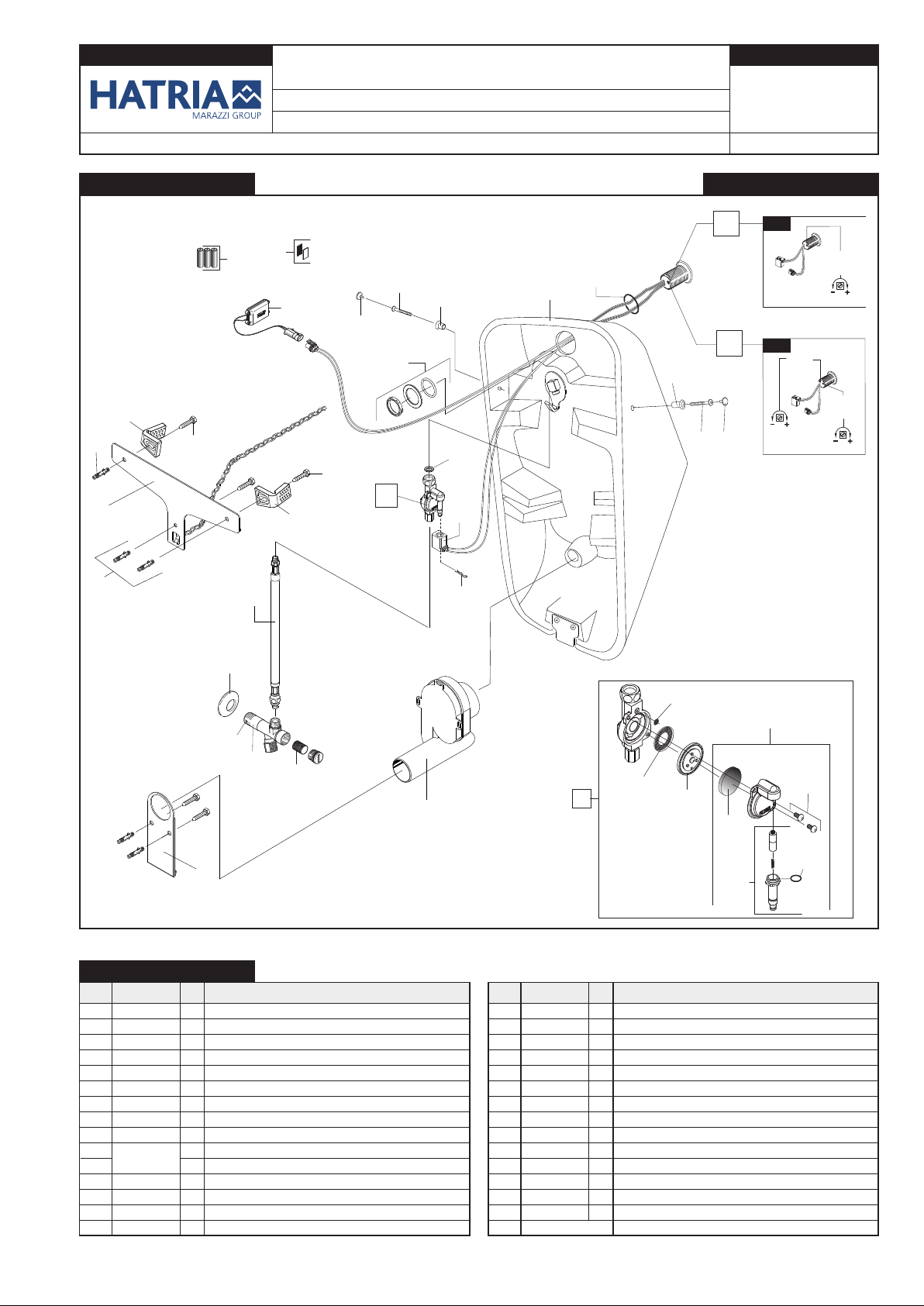
FUSION BATT
ORINATOIO ELETTRONICO IN CERAMICA CON CIRCUITO COMPATTO
dal N° di matricola 732.340 del 16-12-2009
SCHEDA RICAMBI
CODICE
YXC1
VT 01/11
REV. 3
RIF. COD. DMP PZ. DESCRIZIONE RIF. COD. DMP PZ. DESCRIZIONE
ELENCO RICAMBI
11
7
12
8
11.2
11.5
11.4
11.1
11.3
11.6
11.7
11
5
19
15
16
2
3
3
4
4
4
4
4
14
18
17
1
4
10
9.1
9.3
1/2G
15
16
13
13
MAX
MIN
MAX
MIN
Tempo
uscita
acqua
MAX
MIN
Sensibilit
Raggio
d’azione
Sensibilit
Raggio
d’azione
SB39
SB38
EURO
DMP
EURO
DMP
6.1
6.2
11.8
9.2
DISEGNO ESPLOSO
11.2 R/61982 1 Filtro inox a pasti lia Ø25
11.3 R/61186 1 Filtro inox ø23 per elettrovalvola
11.4 R/61511 2 Vite TCC M3x6 inox
11.5 R/22212 1 O-Rin 1,5 x 1,8
11.6 R/09102 1 Pistoncino completo EURO-DMP
11.7 R/09100 1 Kit trasf. coperchio elettrovalvola EURO-DMP
11.8 R/09073 1 O-Rin 7 x 1
12 R/61506 1 Scatoletta portapile DMP con connettore
13 R/62219 1 Tappo bianco coprivite FISCHER
14 R/61526 1 Guarnizione da 3/8 G
15 R/62214 2 Vite autofilettata 4,8x40 c/foro
16 R/62215 2 Boccola plastica per vite fissa io orinatoio HATRIA
17 R/62032 1 O-Rin 42,52 x 2,62
18 R/62033 1 Kit fissa io circuito LEO - TD
19 Non disponibile Bobina incorporata al circuito
CON EURO-DMP
ALIMENTAZIONE 3 PILE ALKALINE SIZE-AA - 3 x 1,5V
1 R/62205 1 Orinatoio ceramico FUSION
2 R/61602 1 Scarico plastico ø 40 mm
3 R/62206 1 Piastra sup.+inf. per fissa io a muro FUSION
4 R/62207 5 Tasselli più viti SLM 10 - inox + 2 anci an olari
5 R/61653 1 Clip per fissa io bobina
6.1 R/09115 1 Circuito “SB38” AVVICINAMENTO
6.2 R/62216 1 Circuito “SB39” ALLONTANAMENTO
7 R/23052 1 Adesivo a strappo per portapile
8 R/61518 3 Pila alkalina Size “AA” LR6 - 1,5 V
9.1 R/62220 1 Rubinetto d’arresto DMP senza valvola di non ritorno
9.2 1 Rosone con foro 1/2
9.3 R/61553 1 Filtro per rubinetto d’arresto - ø 15x16
10 R/62078 1
Tubo flex cm 40 con O-Rin + dado 3/8 innesto - Fil. SIN
11 R/62212 1 Elettrovalvola FUSION con filtro
11.1 R/61513 1 Membrana senza foro
Popular Toilet manuals by other brands


Glacier bay
Glacier bay N2430E Use and care guide

WinZo
WinZo WZ5028 installation instructions

Toto
Toto WASHLET SW3084T40 instruction manual

Villeroy & Boch
Villeroy & Boch 9M33 quick start guide

American Standard
American Standard Homestead VorMax owner's manual

Thetford
Thetford Campa Potti Excellence user manual