Hatteland HT 416 User manual

User Manual HT 216 / HT 416
Updated: 02 May 2012 Doc Id: INB100084-1 (Rev 14)
Created: 363
Approved: 6987
HT 216 xxx-Ayyy
HT 416 xxx-Ayyy
xxx=standard or customized
yyy=conguration dependent
USER MANUAL
HT 216 / HT 416 - Maritime Rack Computers
Hatteland Display AS, Åmsosen, N-5578 Nedre Vats, Norway
Tel: (+47) 4814 2200 - mail@hatteland-display.com - www.hatteland-display.com
Please visit www.hatteland-display.com for the latest electronic version of this manual.

Copyright © 2012 Hatteland Display AS
Aamsosen, N-5578 Nedre Vats, Norway
Information in this manual is copyrighted to the respective owners. All rights are reserved by
Hatteland Display AS. This information may not, in whole or in part, be copied, photocopied, reproduced,
translated or reduced to any electronic medium or machine-readable form without the prior written consent
of Hatteland Display AS.
The products described, or referenced, herein are copyrighted to the respective owners.
The products may not be copied or duplicated in any way. This documentation contains proprietary
information that is not to be disclosed to persons outside the user’s company without prior written consent
of Hatteland Display AS.
The copyright notice appearing above is included to provide statutory protection in the event of
unauthorized or unintentional public disclosure.
All other product names or trademarks are properties of their respective owners !
WARNING: This is a class A product. In a domestic environment this product may cause radio interference
in which case the user may be required to take adequate measures.

3
IND100206-22
INB100084-1 (Rev 14)
Contents
Contents.................................................................................... 3
Contents of package ..........................................................................5
General ...................................................................................... 7
About this manual...............................................................................8
About Hatteland Display.....................................................................8
www.hatteland-display.com ................................................................8
Contact Information............................................................................8
Computers introduction ......................................................................9
Basic Construction ...........................................................................10
Product Labels (Examples) ..............................................................12
Serial Number Label Placement and Layout (external) ...............12
Operating System Serial Number Label Placement (external) ....12
Installation............................................................................... 13
Installation and mounting of computers............................................14
Cables ..............................................................................................15
Conguring DC power input housing connector...........................15
Ferrites .............................................................................................15
Sliding Rails - HT 00250 OPT-A1.....................................................16
Computer Upgrade Precaution Note................................................17
Operation .........................................................................................18
Front area - HT 216 computer......................................................18
Front area - HT 416 computer......................................................18
Physical Connections.......................................................................20
Connector area - HT 216 computer .............................................20
Connector area - HT 416 computer .............................................20
Specications ......................................................................... 23
Specications - HT 216 ....................................................................24
Specications - HT 416 ....................................................................25

Contents
4
IND100206-22
INB100084-1 (Rev 14)
Technical Drawings ................................................................ 27
Technical Drawings - HT 216 ...........................................................28
Technical Drawings - HT 416 ...........................................................29
Technical Drawings - Accessories........................................ 31
Technical Drawings - HT 00250 OPT-A1.......................................... 32
Appendixes ............................................................................. 33
Pinout Assignments - Common Connectors.....................................34
Pinout Assignments - HT 216/HT 416 Additional COM Ports...........36
Trouble-shooting ..............................................................................37
Declaration of Conformity.................................................................38
Return Of Goods Information ...........................................................39
Terms................................................................................................40
Revision History ...............................................................................43

5
IND100207-10
INB100084-1 (Rev 14)
Item Description Illustration
FS-CABLE EU
1 pcs of power cable European Type F “Schuko” to IEC.
Length 1.8m
EUR TYPE F
IEC
80099
1 pcs of power cable US Type B plug to IEC.
Length 1.8m US TYPE B IEC
MEDIA STD01
Documentation and Driver DVD for factory installed components like
mainboard, IDE, network etc.
Note: To use this DVD disc you will need an external USB CD/DVD drive or
provide means of getting contents copied over via USB memory stick/network
to the operating system. You can alternatively download the drivers from our
website www.hatteland-display.com
Menu and Driver
browser for
Microsoft®
Windows®
1 pcs of cable relief bracket including screws.
Test Reports papers:
1 pcs of Product Declaration
1 pcs of Computer Checklist
1 pcs of Burn-In Test Certificate
This product is shipped with:
Contents of package
Package may also include: (based on accessories/options ordered)
Item Description Illustration
HT 00215 OPT-A1
Recovery Kit (USB Flash)
For reverting back to factory/customized installations.
Note: Only applicable for factory delivered units with HDD/SSD hardware.
HT 00250 OPT-A1
Mounting rails kit
2 x 20 inch long ball bearing sliding rails. 19 inch Rack compatible.
?For computers that include 3rd party hardware; the package /
accessories box may also include additional CD / HW / Information from
3rd party supplier(s).

6INB100084-1 (Rev 14)
This page left intentionally blank

7INB100084-1 (Rev 14)
General

8
Hatteland Display AS
IND100077-1
INB100084-1 (Rev 14)
General
About this manual
The manual contains electrical, mechanical and input/output signal specications. All specications in this manual,
due to manufacturing, new revisions and approvals, are subject to change without notice. However, the last update
and revision of this manual are shown both on the frontpage and also in the “Revision History” chapter at the end of
the manual.
Furthermore, for third party datasheet and user manuals, please see dedicated Documentation and Driver DVD
delivered with the product or contact our sales/technical/helpdesk personnel for support.
About Hatteland Display
Hatteland Display is the leading technology provider of specialized display and computer products, delivering high
quality, unique and customized solutions to the international maritime, naval and industrial markets.
The company represents innovation and quality to the system integrators world wide. Effective quality assurance and
investment in sophisticated in-house manufacturing methods and facilities enable us to deliver Type Approved and Mil
tested products. Our customer oriented approach, technical knowledge and dedication to R&D, makes us a trusted
and preferred supplier of approved solutions, which are backed up by a strong service network.
www.hatteland-display.com
You will nd our website full of useful information to help you make an informed choice as to the right product for your
needs. You will nd detailed product descriptions and specications for the entire range on Displays, Computers and
Panel Computers, Military solutions as well as the range of supporting accessories. The site carries a wealth of
information regarding our product testing and approvals in addition to company contact information for our various
ofces around the world, the global service centers and the technical help desk, all ensuring the best possible
support wherever you, or your vessel, may be in the world.
Contact Information
Head ofce, Vats / Norway:
Hatteland Display AS
Åmsosen
N-5578 Nedre Vats, Norway
Tel: +47 4814 2200
Fax: +47 5276 5444
mail@hatteland-display.com
Sales ofce, Frankfurt / Germany:
Hatteland Display GmbH
Werner Heisenberg Strasse 12,
D-63263 Neu-Isenburg, Germany
Tel: +49 6102 370 954
Fax: +49 6102 370 968
Sales ofce, Oslo / Norway:
Solbråveien 20
N-1383 Asker
Norway
Tel: +47 4814 2200
Fax: +47 5276 5444
Sales ofce, Aix-en-Provence / France:
Hatteland Display SAS
ACTIMART, 1140 RUE AMPERE, BP 50 196
13795 AIX-EN-PROVENCE, CEDEX 3
France
Tel: +33 (0) 4 42 16 47 57
Fax: +33 (0) 4 42 16 47 00
Sales ofce, San Diego / USA:
Hatteland Display Inc.
11440 W. Bernardo Court, Suite 300
San Diego, CA 92127, USA
Tel: +1 858 753 1959
Fax: +1 858 430 2461
For an up-2-date list, please visit www.hatteland-display.com/locations

9
Computers
IND101057-2
INB100084-1 (Rev 14)
General
Computers introduction
Hatteland Display’s range of type-approved computers is designed to
perform in harsh environments while providing the performance and
flexibility you expect. We offer rack mount and black box/standalone
computer solutions for every need. Our computers are used by system
integrators, boat builders and end-users and can be found on all vessel
types, all over the world.
If you are looking for a high quality computer for navigation, monitoring
or entertainment solutions, Hatteland Display can fulfil your high
expectations at a reasonable cost.
Our computer range covers all eventualities and requirements. We offer
a wide range of processor choices, HDD and power options, and solid
state technology, neatly engineered within industry standard form factors
such as 19” rack mount, 2U, 3U and 4U.
We continually develop our computers portfolio to make the best use of
emerging computer technology so you can be sure that your Hatteland
Display computer offers the power needed to run modern applications,
with the flexibility to be installed wherever you want, for any marine use.
Designed to perform in harsh environments...
Winner of Red Dot awards 2009 / 2007
In 2009 the Hatteland Display HT C01 standalone computer won
a prestigous Red Dot Award with Honourable Mention distinction,
sucessfull detail solution.
The Design Zentrum Nordrhein Westfalen in Germany has been marking
outstanding international product design with its famous and highly
regarded dot since 1955. The Red Dot Product Design Award is an
annual international awards scheme where products from all industries
are chosen for their innovative visual and industrial design.
In 2007 the Hatteland Display Series 2 Display/Panel Computers
range won the Red Dot Award for the overall design and modular
backpack concept, which docks into the screen at the back, comprises
either the typical display connections or a fully equipped panel computer.
Even the computer backpack can operate on its own as a stand-alone
computer.
10
IND100077-89
INB100084-1 (Rev 14)
General
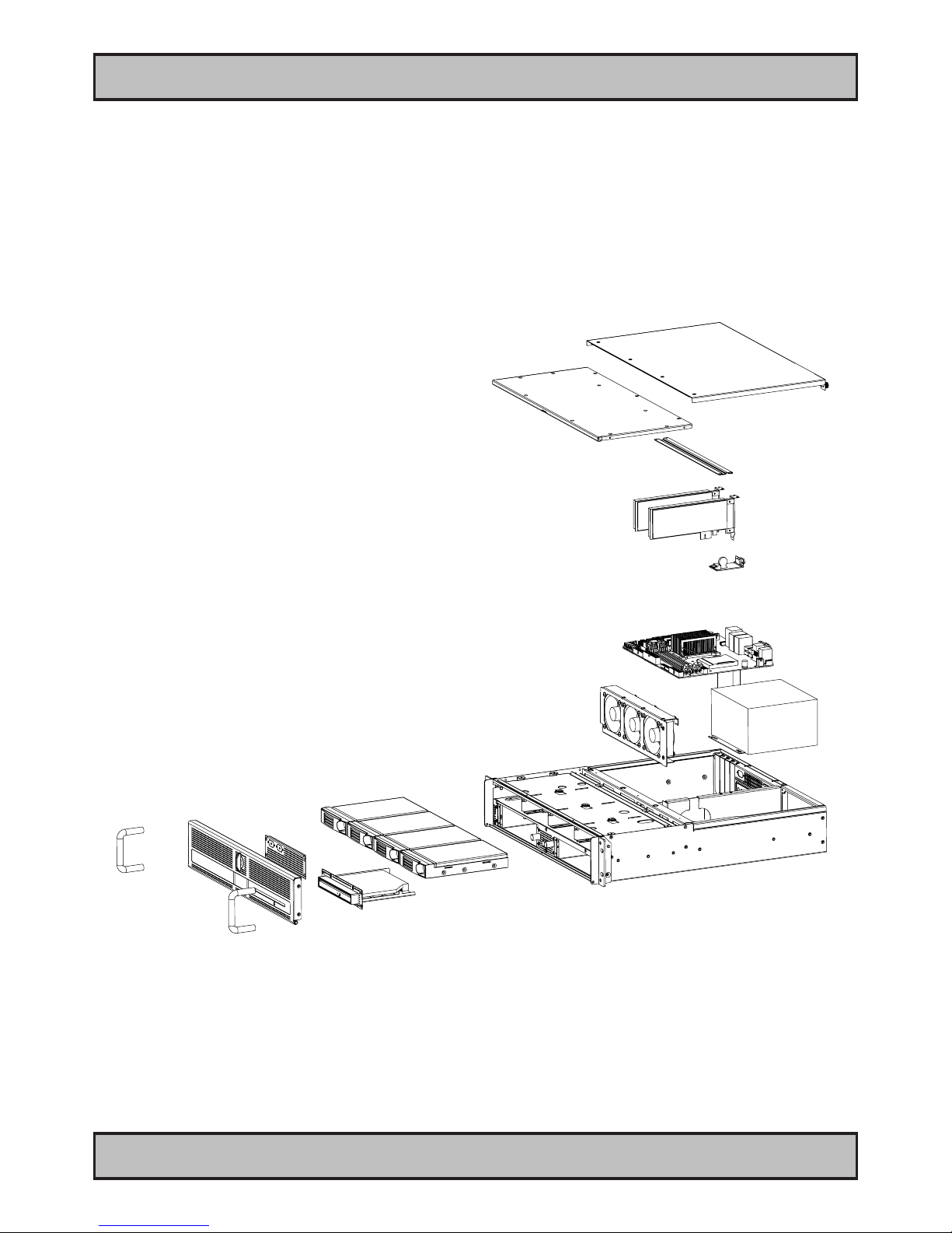
Basic Construction
Exploded View HT 216
General illustration

11
Basic Construction
IND100077-89
INB100084-1 (Rev 14)
General
Exploded View HT 416
General illustration
12
Product Labels (Examples)
IND100240-6
INB100084-1 (Rev 14)
General
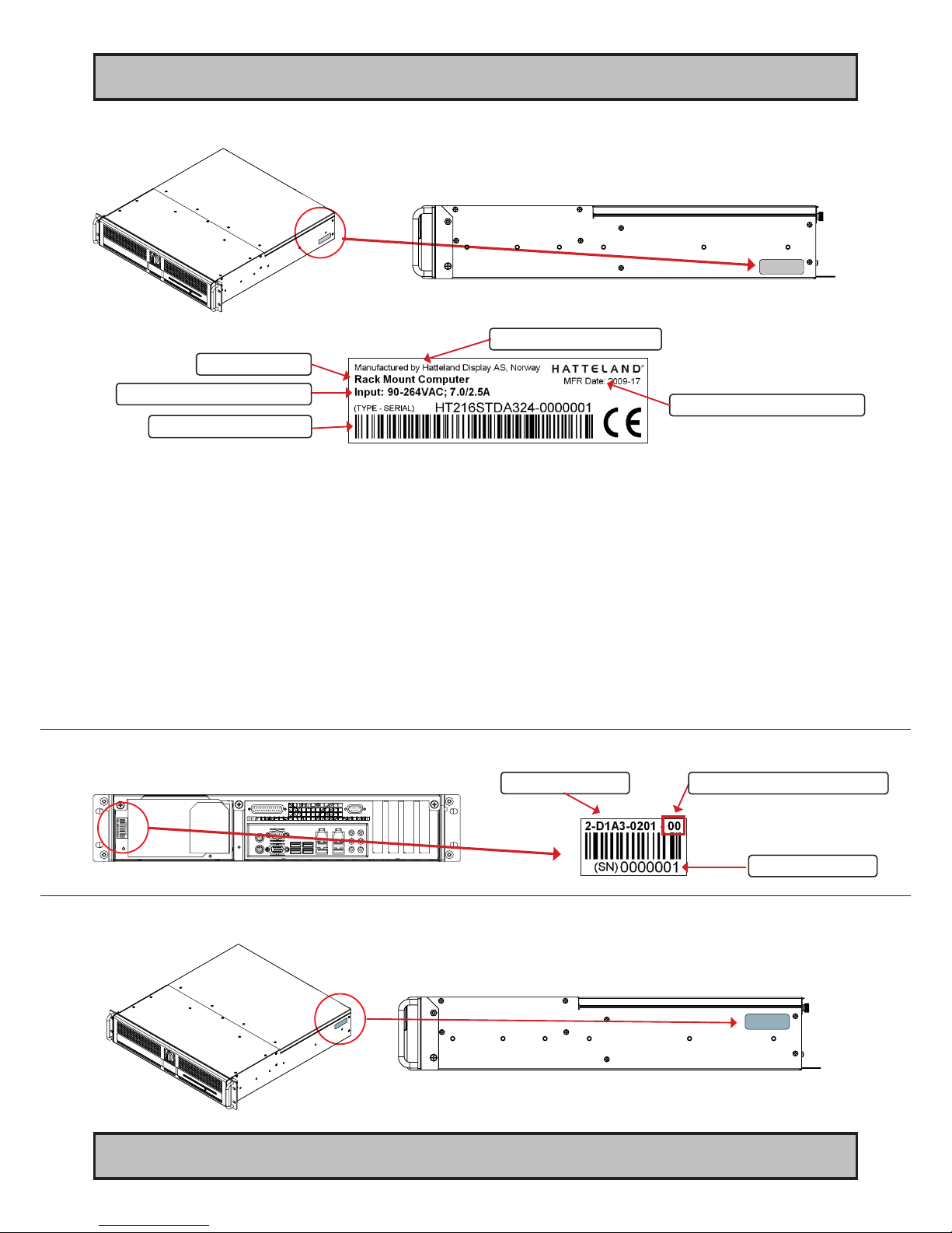
Product Labels (Examples)
Serial Number Label Nomenclature
Product Type
Manufacturer & Country
Input Voltage & Power Rating Manufactured Date yyyy-ww
Serial Number Label Placement and Layout (external)
Operating System Serial Number Label Placement (external)
Note: This location also apply
for HT 416 units.
Note: This location also apply
for HT 416 units.
AA XXX AAA-Axxx-XXXXXX NOMENCLATURE - A=Letters, X=Numbers
HT 216 STD-A111-000005 Example
|| ||| ||| |||| ||||||
|| ||| ||| |||| ¤----- Serial Number, 7 digits
|| ||| ||| |¤¤¤------- Conguration ID (for components like memory, storage etc.)
|| ||| ||| ¤---------- Power Input ID (A=90-264VAC)
|| ||| ||¤------------ Installed Operating System ID / No Installed OS ID
|| ||| ¤¤------------- Abbreviation for Standard (ST) or reserved customer ID
|| ||¤---------------- Chassis Revision ID
|| |¤----------------- Electronics / Mainboard / Technology Revision ID
|| ¤------------------ Chassis Form Factor (2=2U, 4=4U)
¤¤-------------------- Manufacturer ID / Product Series ID
Revision Label
Barcode 128 (SNO)
Barcode 128 (TYP+SNO)
Hardware Revision (HWcode)
Production Code
Label Size: 6cm x 2cm
Label Size: 7cm x 2.8cm

13 INB100084-1 (Rev 14)
Installation

14
IND100210-1
INB100084-1 (Rev 14)
Installation
Installation and mounting of computers
1. Units may be intended for various methods of installation or mounting (rack mounting, panel mounting,
bracket mounting, ceiling/wall mounting); for details, please see the relevant mechanical drawings.
2. Adequate ventilation is a necessary prerequisite for the life of the unit. The air inlet and outlet openings must
denitely be kept clear; coverings which restrict ventilation are not permissible. The product might be without
any ventilation aperatures which means pt.2 does not apply.
3. Exposure to direct sunlight can cause a considerable increase in the temperature of the unit, and might under
certain circumstances lead to overtemperature. This point should already be taken into consideration when
the bridge equipment is being planned (sun shades, distance from the windows, ventilation, etc.)
4. Space necessary for ventilation, for cable inlets, for the operating procedures and for maintenance, must be
provided.
5. To further improve the cooling of the unit we recommend installing Cooling Fans underneath blowing upwards
into the unit air inlet. This may be required in high temperature applications and also when there is reason to
expect temperature problems due to non-optimal way of mounting.
6. For DC powered computer units proper grounding must be achieved by connecting a wire from the unit’s
ground (GND) screw (as indicated on the unit with a icon) to the grounding in your installation setup.
The wire should have a cross sectional area of at least 6mm2. The GND screw is located near the other I/O
connectors. Please review the “Physical Overview” chapter for further help.
7. Expose to heavy vibration and acoustic noise might under certain circumstances affect functionality and
expected lifetime. This must be considered during system assembly and installation. Mounting position must
carefully be selected to avoid any exposure of amplied vibration.
General mounting instructions
1. The useful life of the components of all Electronics Units generally decreases with increasing ambient
temperature; it is therefore advisable to install such units in air-conditioned rooms. If there are no such
facilities, these rooms must at least be dry, adequately ventilated and kept at a suitable temperature in order
to prevent the formation of condensation inside the unit.
2. With most Electronic Units, cooling takes place via the surface of the casing. The cooling must not be
impaired by partial covering of the unit or by installation of the unit in a conned cabinet.
3. In the area of the wheel house, the distance of each electronics unit from the magnetic standard compass or
the magnetic steering compass must not be less than the permitted magnetic protection distance. This
distance is measured from the centre of the magnetic system of the compass to the nearest point on the
corresponding unit concerned. The exact distance is often mentioned in the specic product specications.
4. Transportation damage, even if apparently insignicant at rst glance, must immediately be examined and be
reported to the freight carrier. The moment of setting-to-work of the equipment is too late, not only for
reporting the damage but also for the supply of replacements.
5. The classication is only valid for approved mounting brackets provided by Hatteland Display. The unit shall
be mounted stand-alone without any devices or loose parts placed at or nearby the unit. Any other type of
mounting might require test and re-classication.
General Installation Recommendations

15
IND100210-1
INB100084-1 (Rev 14)
General Installation Recommendations
Installation
Cables
Use only high quality shielded signal cables. For RGB/DVI cables use only cables with separate coax for Red, Green
and Blue.
Conguring DC power input housing connector
Note: Only applicable for certain models!
For installations that require DC power input, use the provided
2-pin DC Power Input housing with internal cable screw terminal.
1: Open the housing
2: Unmount the fasteners. (FIG 1)
3: Mount power cables to screw terminal (FIG 2). Note polarity!
4: Secure the cable tightly with fasteners (FIG 3, FIG 1)
5: Close the housing
Note: Please check polarity before connecting any cables
to the screw terminal.
Ferrites
On selected products, the ferrites prevent high frequency
electrical noise (radio frequency interference) from exiting or
entering the equipment. To verify if your product require this,
please see the “Physical Overview” chapter in this manual. The
ferrites are part of the contents of the package also specied in the
“Contents Of Package” chapter early in this manual. The ferrites
must be mounted on specic cables to fully comply with the
Type Approvals!
The ferrites should be mounted (clipped in place on the cable as
shown in illustration) as close as possible to the cable connector
on the rear side of the computer product. Open up the ferrite,
place the cable inside as shown in FIG1, and then gently close it
until a click can be heard (FIG2).
Screw terminal
FIG 1
FIG 2
FIG 3
+ -
+ -
+
-
FIG1
To computer
FIG2
To computer

16
IND100210-7
INB100084-1 (Rev 14)
General Installation Recommendations
Installation
Sliding Rails - HT 00250 OPT-A1
Suitable for use with 19 Inch rack mounting. Load rating up to 52kg, 9.6mm slide thickness. Lock-out. Front
Disconnect. Optional enclosure mounting brackets. Note: Manufactured by 3rd party. Sliding rails representation
below are simplied in terms of visual appearance.
1: Pull out the rails to extend it fully
2: Note the locations of suitable mounting holes on the 2U/4U cabinet for the sliding rails
3: Mount the rails on left and right side of the 2U/4U cabinet. You may need to align the entire slide construction to
discover the suitable mounting holes. M4 screws are suitable (included in kit).
4: Mount the additional bracket kit into your 19 Inch rack if needed. Comes complete with brackets, gaskets and
mounting screws.

17
IND100210-4
INB100084-1 (Rev 14)
General Installation Recommendations
Installation
Computer Upgrade Precaution Note
Users who needs to open the computer to change PCI cards, install more memory, or set internal jumpers can do so
without voiding the warranty. Before opening a unit’s housing to remove or touch a board, proper ESD measurements
must be taken!
1. Operator should ground himself by using a wrist band.
2. The wrist band should be connected to ground via a ground cord.
3. A one megaohm resistor, installed in the wrist connection end of the ground cord, is a safety
requirement.
4. Alternatively an Static-dissipative ESD work mat could be positioned at the workplace.
The 3M™ 8501 Portable Field Service Kit is a good choice for this purpose.
All assisting persons who might come into contact with the endangered boards must also use the ESD equipment.
CAUTION
This unit contains electrostatic sensitive devices.
Observe precautions for handling.
18 INB100084-1 (Rev 14)
IND100133-38
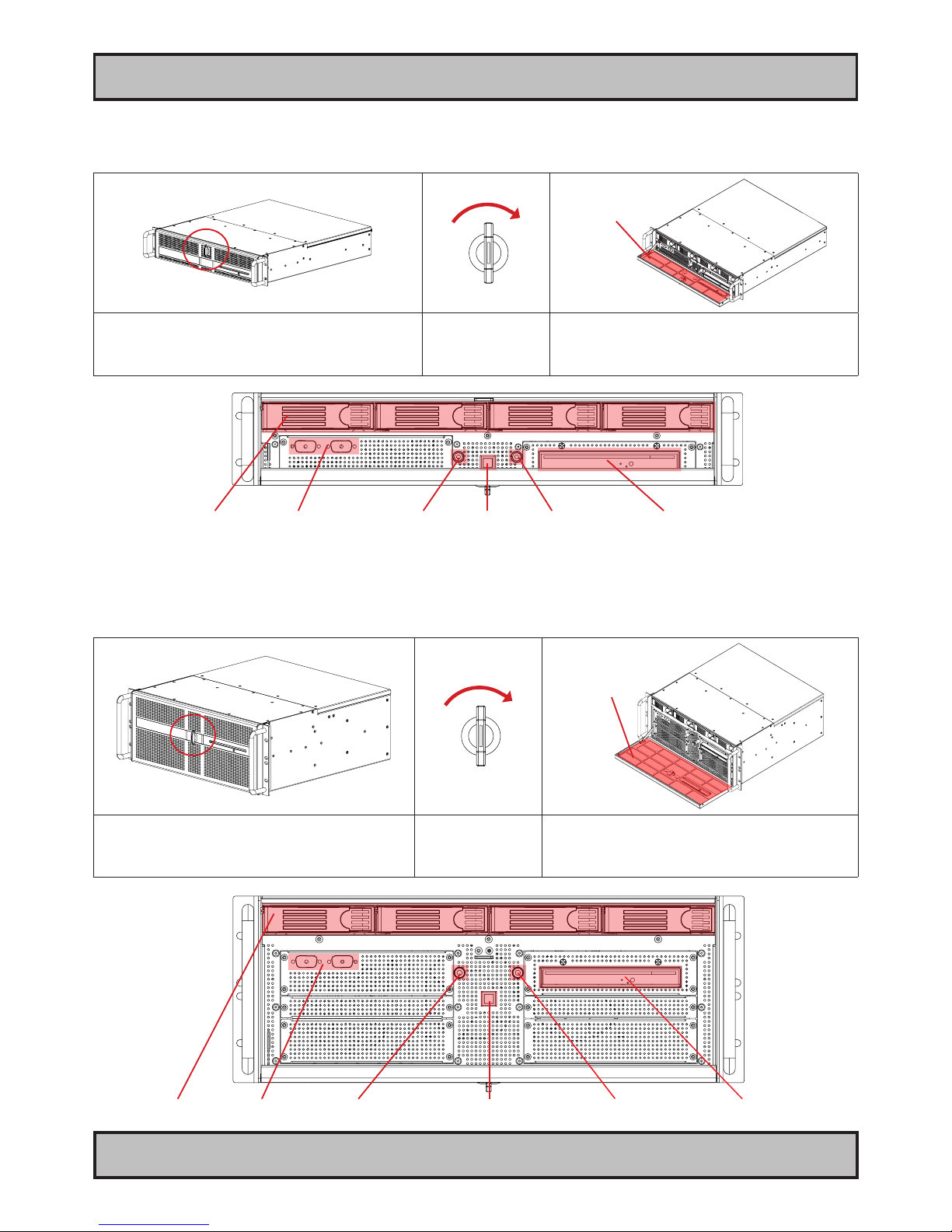
Front area - HT 216 computer
The unit’s operational controls and air lter are located behind the lockable front hatch.
Air Filter
1: Showing unit with hatch closed and front lock. 2: Press gently the
front lock inwards and
turn clockwise at the
same time to unlock.
3: Showing unit with hatch open to reveal both user
controls and air lter. See next page for details.
Operation
Front area - HT 416 computer
The unit’s operational controls and air lter are located behind the lockable front hatch.
Air Filter
1: Showing unit with hatch closed and front lock. 2: Press gently the
front lock inwards and
turn clockwise at the
same time to unlock.
3: Showing unit with hatch open to reveal both user
controls and air lter. See next page for details.
Reserved Power LED Media Drive
Power Button HDD LED
HDD
Reserved Power LED Media Drive
Power Button HDD LED
HDD

19 INB100084-1 (Rev 14)
IND100133-38
Operation
HDD TRAY 1,2,3,4:
Replaceable HDD tray bay which supports 3.5” SATA hard drives. The amount of HDD available and installed is
conguration dependent. By factory default, 1 x HDD is installed. Any HDD should not be replaced or dismounted from
the unit while the operating system is running and the computer unit is turned on. Doing so may cause loss of data or
software crashes upon reboot.
RESERVED:
These D-SUB shaped blinded holes are reserved for future applications.
POWER LED:
The Power LED will illuminate static green when the computer unit is powered and turned on.
Power Button:
To turn ON the computer, press down button and release it immediately. The Power LED will illuminate green and any
operating system installed will automatically boot. To turn OFF the computer, press down this button and hold it for 3
seconds. The operating system may require additionally tasks to be performed before computer shuts down and turns
off the unit. You can also turn off the computer by using the operating system own “shut down” feature. Either to stand-
by mode, hibernation or sleep is also possible from most operating systems.
HDD LED:
The HDD LED will illuminate red when there is read/write activity on any of the installed HDD in the HDD trays. When
there is no HDD activity the LED will be off.
MEDIA DRIVE:
By factory default a DVD/CD-RW recorder/player is installed. The drive features an eject button, a read/write activity
LED and a small hole to eject any media even if the computer unit is not powered on.
AIR FILTER:
The computer unit features an cleanable / replaceable air lter. This is located onto the front hatch as seen in the
previous page. Clean this regulary (based on environmental factors) to allow the unit to continuously cool properly and
to prolong the unit’s lifetime and the components inside.

20 INB100084-1 (Rev 14)
IND100133-38
Physical Connections
Connector area - HT 216 computer
Note: PCI slots may provide DVI-I or other functionality not visible in the general illustration below.
Power Input
Keyboard PortMouse Port
Network GBLAN
USB 9,8,7,6,5,4,2,0 Mic In, Front Out, Line in
COM 2 PCIe X16 (add2)
LPT
VGA RGB
PCI
PCIe X4
PCI
Connector area - HT 416 computer
Note: PCI slots may provide DVI-I or other functionality not visible in the general illustration below.
COM 1 Center Out, Side Out, Rear Out
Power Input Network GBLAN COM 2
PCIe X16 (add2)
LPT PCI
PCIe X4
PCI
PCI
PCI
PCI
Keyboard PortMouse Port
USB 9,8,7,6,5,4,2,0 Mic In, Front Out, Line in
VGA RGB
COM 1 Center Out, Side Out, Rear Out
Table of contents
Other Hatteland Desktop manuals

Hatteland
Hatteland HT B17 Series User manual

Hatteland
Hatteland HT 405P4 STD User manual

Hatteland
Hatteland JH 23T02 MMC User manual

Hatteland
Hatteland JH 15T17 MMC series User manual

Hatteland
Hatteland HT 221 User manual

Hatteland
Hatteland HT 405P4 STD User manual

Hatteland
Hatteland JH I2TOI MMC User manual

Hatteland
Hatteland 1 Series User manual

Hatteland
Hatteland HT B17 Series User manual

Hatteland
Hatteland HT 403XE STD User manual


