Hatteland JH 15T17 MMC series User manual
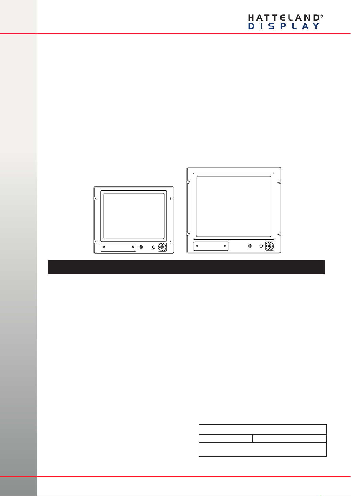
JH 15T17 MMC-xxx-Axxx - 15.0 inch Maritime Multi Computer
JH 15T17 MMC-xxx-Axxx - 15.0 inch Maritime Multi Computer (LED version)
JH 19T14 MMC-xxx-Axxx - 19.0 inch Maritime Multi Computer
JH 19T14 MMC-xxx-Axxx - 19.0 inch Maritime Multi Computer (LED version)
Series 1 - Maritime Multi Computer Models
USER MANUAL
Hatteland Display AS, Stokkastrandvegen 87B, N-5578 Nedre Vats, Norway
Tel: (+47) 4814 2200 - mail@hatteland-display.com - www.hatteland-display.com
Please visit www.hatteland-display.com for the latest electronic version of this manual.
User Manual MMC Series 1
Updated: 09 Apr 2015 Doc Id: INB100216-1 (Rev 13)
Created: 363
Approved: 6405

Copyright © 2015 Hatteland Display AS
Stokkastrandvegen 87B, N-5578 Nedre Vats, Norway.
All rights are reserved by Hatteland Display AS. This information may not, in whole or in part, be
copied, photocopied, reproduced, translated or reduced to any electronic medium or machine-
readable form without the prior written consent of Hatteland Display AS. Review also:
www.hatteland-display.com/pdf/misc/doc100703-1_permission_to_create_user_manuals.pdf
The products described, or referenced, herein are copyrighted to the respective owners.
The products may not be copied or duplicated in any way. This documentation contains proprietary
information that is not to be disclosed to persons outside the user’s company without prior written consent
of Hatteland Display AS.
The copyright notice appearing above is included to provide statutory protection in the event of
unauthorized or unintentional public disclosure.
All other product names or trademarks are properties of their respective owners !
WARNING: This is a class A product. In a domestic environment this product may cause radio interference
in which case the user may be required to take adequate measures.
Last revised 6 Jan 2015

3
IND100130-37
Contents.......................................................................................... 3
Contents of package.......................................................................................... 5
General ............................................................................................ 7
About this manual.............................................................................................. 8
About Hatteland Display .................................................................................... 8
www.hatteland-display.com ............................................................................... 8
Contact Information ........................................................................................... 8
Maritime Multi Computer (MMC) - Introduction ................................................. 9
Basic Construction........................................................................................... 10
Product Labeling...............................................................................................11
Front Hatch Logo Label .............................................................................. 14
Touch screen products .................................................................................... 15
Introduction to products with touch screen ................................................. 15
Touch Screen Drivers and Documentation ................................................. 16
Installation..................................................................................... 17
Installation and mounting................................................................................. 18
Ergonomics...................................................................................................... 19
Cables ............................................................................................................. 20
Cable Entries & Connectors (Marked area) - Illustration only..................... 20
Maximum Cable Length .............................................................................. 20
Conguring DC power input housing connector ......................................... 20
Rotary Bracket and Mounting Bracket (15 inch) combined assembling .......... 21
Rotary Bracket and Mounting Bracket (17-26 inch) combined assembling..... 22
Physical Connections - MMC / xxC based units.............................................. 23
Operation....................................................................................... 25
User Controls................................................................................................... 26
Status LED Overview ...................................................................................... 28
For ECDIS Calibrated Products....................................................................... 28
Specications ............................................................................... 29
Specications - JH 15T17 MMC-xxx-Axxx (CCFL version) ............................. 30
Specications - JH 15T17 MMC-xxx-Axxx (LED version) ............................... 31
Specications - JH 19T14 MMC-xxx-Axxx (CCFL version) ............................. 32
Specications - JH 19T14 MMC-xxx-Axxx (LED version) ............................... 33
Contents

Contents
4
IND100130-37
Technical Drawings ...................................................................... 35
Technical Drawings - JH 15T17 MMC-xxx-Axxx.............................................. 36
Standard Version ........................................................................................ 36
Technical Drawings - JH 19T14 MMC-xxx-Axxx.............................................. 37
Standard Version ........................................................................................ 37
Technical Drawings - Accessories.............................................. 39
Sun Visor - 15” ................................................................................................ 40
Sun Visor - 19” ................................................................................................ 41
Rotary Bracket - 15” ....................................................................................... 42
Rotary Bracket - 17” to 26” ............................................................................. 43
Bracket - 15” ................................................................................................... 44
EN60945 Bracket - 19” ................................................................................... 45
RACK Adapter - 15” TFT to 19” ...................................................................... 46
CRT Adapter - 15” TFT to 17” ......................................................................... 47
CRT Adapter - 19” TFT to 21” ......................................................................... 48
CRT Adapter Custom - 19” TFT to 21” ........................................................... 49
VESA Bracket - 15”.......................................................................................... 50
VESA Bracket - 19”.......................................................................................... 51
Water Cover - 15” ............................................................................................ 52
Water Cover - 19” (HW01)............................................................................... 53
Appendixes ................................................................................... 55
Pinout Assignments - Common Connectors.................................................... 56
Basic Trouble-shooting .................................................................................... 59
Declaration of Conformity ................................................................................ 60
Return Of Goods Information .......................................................................... 61
General Terms and Conditions ........................................................................ 62
Pixel Defect Policy........................................................................................... 63
Notes ............................................................................................................... 64
General Notes: (For all products)................................................................ 64
Revision History............................................................................................... 65
5
IND100131-22
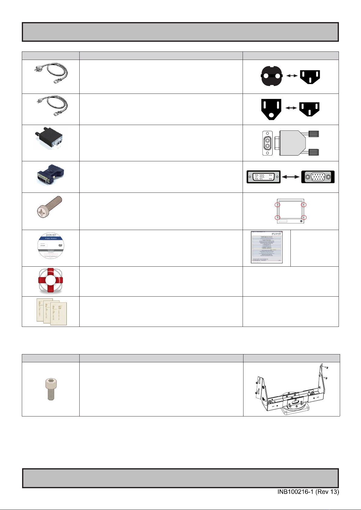
Contents of package
Item Description Illustration
FS-CABLE EU
1 pcs of power cable European Type F “Schuko” to IEC.
Length 1.8m
Note: Included in package for models with AC input.
EUR TYPE F
IEC
80099
1 pcs of power cable US Type B plug to IEC.
Length 1.8m
Note: Included in package for models with AC input.
US TYPE B IEC
FCE17-E2W2SS-2NO &
L17DPPK09JSU (cover)
1 pcs of DC Power Input housing with internal cable screw terminal.
Note: Included in package for models with DC input.
DVI-4
1 pcs of DVI > RGB/VGA adapter
DVI 12+5P Male to DSUB 15P Female
1P06025 (screw) &
16M06012150 (washer)
4 pcs of M6X25 pan screws.
Suitable for securing the display unit into a console cut-out. See illustration to the
right.
DO NOT USE THESE TO MOUNT BRACKETS ONTO THE UNIT.
Use the provided and dedicated screws for accessories (see next table below)
MEDIA STD01
Documentation and Driver DVD for factory installed components like mainboard,
IDE, network etc. It also includes the Touch Screen driver for units delivered with a
factory mounted touch screen.
Note: To use this DVD disc you will need an external USB CD/DVD drive or provide
means of getting contents copied over via USB memory stick/network to MMC unit.
Menu and Driver
browser for
Microsoft® Windows®
Recovery Image
(located on hidden partition on SSD)
Note: Only applicable for factory delivered units with SSD hardware.
Test Report
Item Description Illustration
4 pcs of M6X12 Unbraco bolts. These are included with mounting bracket, if ordered
(review technical drawings chapter).
Should only be used to secure the bracket onto display.
If you prefer your own bolts, make sure they do not exceed 12mm in length. Use any
longer is not possible due to mechanical limits.
Package may also include:

6
This page left intentionally blank

7
General
8
Hatteland Display AS
IND100077-1
General
About this manual
The manual contains electrical, mechanical and input/output signal specications. All specications in this manual,
due to manufacturing, new revisions and approvals, are subject to change without notice. However, the last update
and revision of this manual are shown both on the frontpage and also in the “Revision History” chapter at the end of
the manual.
Furthermore, for third party datasheet and user manuals, please see dedicated Documentation and Driver DVD
delivered with the product or contact our sales/technical/helpdesk personnel for support.
About Hatteland Display
Hatteland Display is the leading technology provider of specialized display and computer products, delivering high
quality, unique and customized solutions to the international maritime, naval and industrial markets.
The company represents innovation and quality to the system integrators world wide. Effective quality assurance and
investment in sophisticated in-house manufacturing methods and facilities enable us to deliver Type Approved and Mil
tested products. Our customer oriented approach, technical knowledge and dedication to R&D, makes us a trusted
and preferred supplier of approved solutions, which are backed up by a strong service network.
www.hatteland-display.com
You will nd our website full of useful information to help you make an informed choice as to the right product for your
needs. You will nd detailed product descriptions and specications for the entire range on Displays, Computers and
Panel Computers, Military solutions as well as the range of supporting accessories. The site carries a wealth of
information regarding our product testing and approvals in addition to company contact information for our various
ofces around the world, the global service centers and the technical help desk, all ensuring the best possible
support wherever you, or your vessel, may be in the world.
Contact Information
Head ofce, Vats / Norway:
Hatteland Display AS
Stokkastrandvegen 87B
N-5578 Nedre Vats, Norway
Tel: +47 4814 2200
Fax: +47 5276 5444
mail@hatteland-display.com
Sales ofce, Frankfurt / Germany:
Hatteland Display GmbH
Werner Heisenberg Strasse 12,
D-63263 Neu-Isenburg, Germany
Tel: +49 6102 370 954
Fax: +49 6102 370 968
Sales ofce, Oslo / Norway:
Solbråveien 20
N-1383 Asker
Norway
Tel: +47 4814 2200
Fax: +47 5276 5444
Sales ofce, Aix-en-Provence / France:
Hatteland Display SAS
ACTIMART, 1140 RUE AMPERE, BP 50 196
13795 AIX-EN-PROVENCE, CEDEX 3
France
Tel: +33 (0) 4 42 16 47 57
Fax: +33 (0) 4 42 16 47 00
Sales ofce, Vista / USA:
Hatteland Display Inc
380 South Melrose Drive,
Suite 349
Vista, CA 92081
USA
Tel: +1 760-643-4061
Fax: +1 858-408-1834
For an up-2-date list, please visit www.hatteland-display.com/locations

9
Panel Computers Series 1
IND101057-1
General
Maritime Multi Computer (MMC) - Introduction
All Series 1 panel computers are based around the high quality,
rugged Series 1 displays. With a panel computer though, the displays
come with a ‘built-in’ computer, instantly transforming them into
navigation and automation powerhouses, ideal for a whole range of
different systems and solutions.
Of course, with Series 1 panel computers you immediately get the
benefits from the Series 1 displays, such as unmatched viewing
clarity and long life, but with the additional flexibility of a computer.
They follow the same form and fit as Series 1 displays too, making
them an ideal match for common system design requirements or as a
replacement computer.
The computer itself is specified to ensure that it is capable of running
all marine applications, from ECDIS software through to engine
monitoring and automation applications. It has power to spare too, so
software developers can be sure that Hatteland Display Series 1 panel
computers can handle the latest applications being designed for bridge
and engine room systems in addition to other, more custom uses.
Series 1 panel computers offer the ultimate in convenience for
systems integrators and boat builders. This is backed up by the
inherent qualities of Series 1 displays and the flexibility of the powerful
integrated computer. Series 1 panel computers are a single flexible
solution, designed only for the marine environment and built to last.
A computer and display, all in one...
- COST EFFECTIVE
- TYPE APPROVED
- ECDIS COMPLIANT
- FORM, FIT, FUNCTION
- SUPERIOR BONDING TECHNOLOGY
10
IND100077-75
General
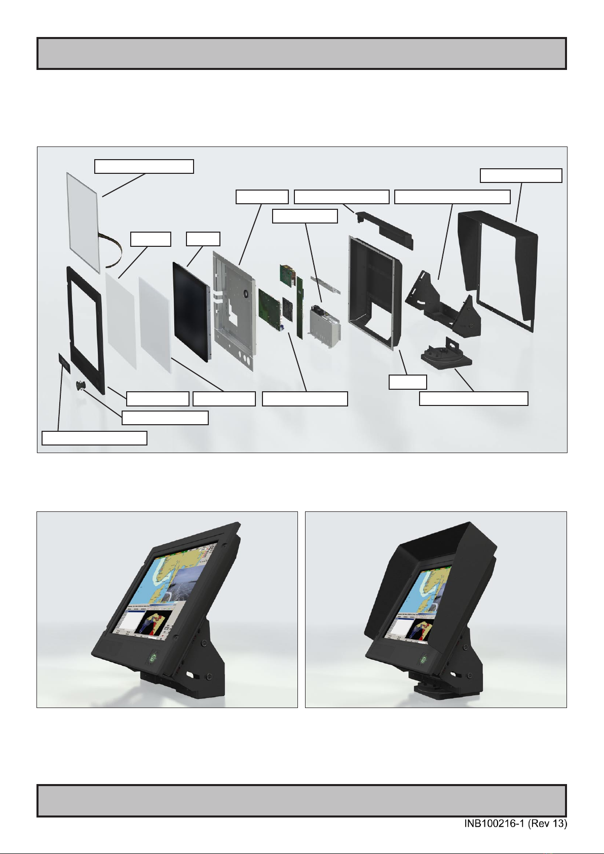
Basic Construction
Basic Construction - Series 1
TFT
Centerbox
Casing
Touch Screen (option)
Logo label (option)
Front Frame
User Controls
Electronics / PCB’s
Glass
Mechanics
Rotary Bracket (option)
Mounting Bracket (option)
Sun Visor (option)
Example with mounting bracket Example with sun visor, mounting bracket and rotary bracket
Bonding
Water Cover (option)
11
IND100077-140
Product Labeling
Introduction
This section details the locations, content details and specications for factory mounted labels for all currently
available standard Hatteland Display Maritime Multi Computer (MMC) - Series 1 models. This information will in most
cases also apply for most Customized Models as well, but may differ based on customer requirements, in that case,
please refer to the customized User Manual (paper or electronic version, dependent on customer requirements).
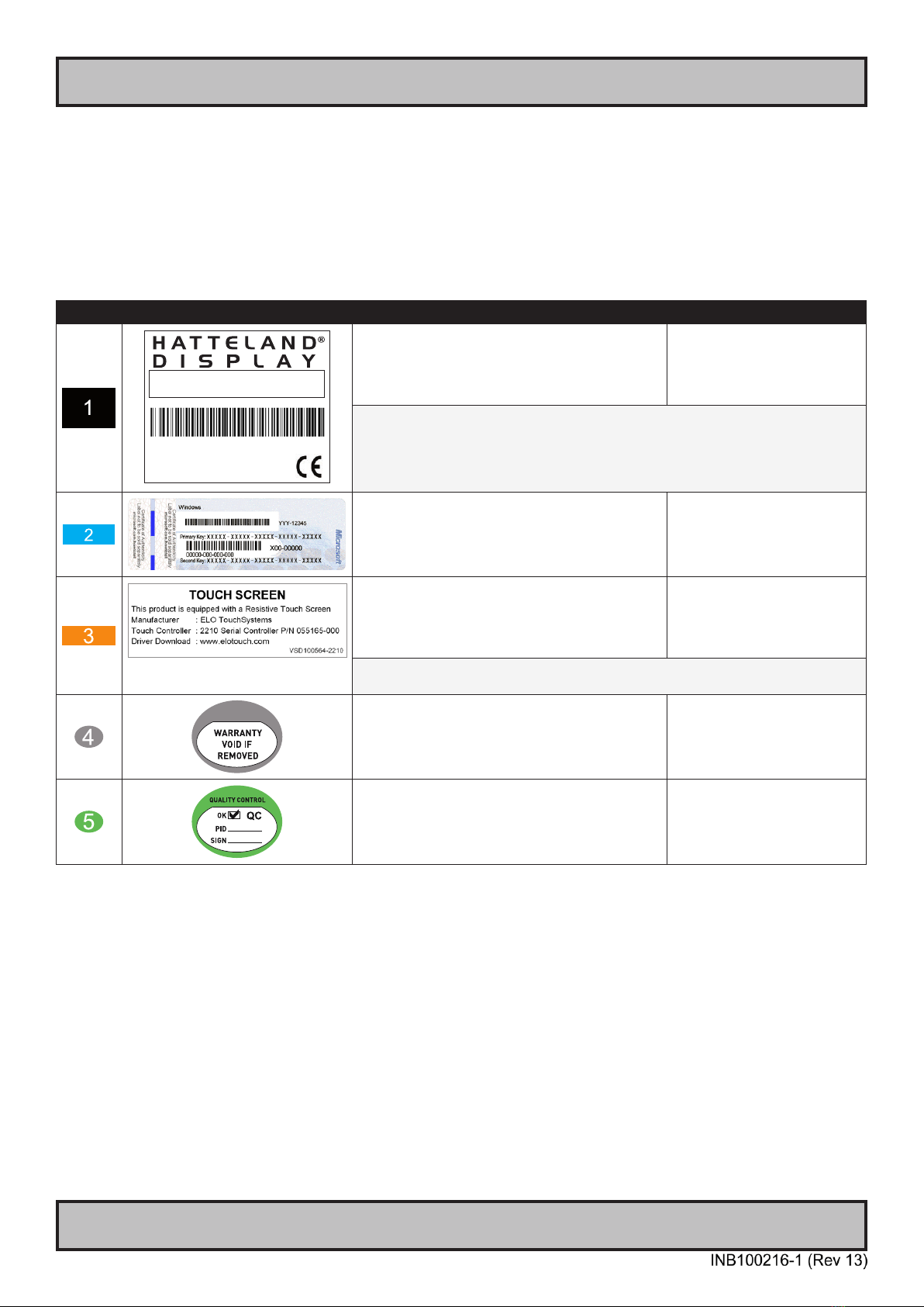
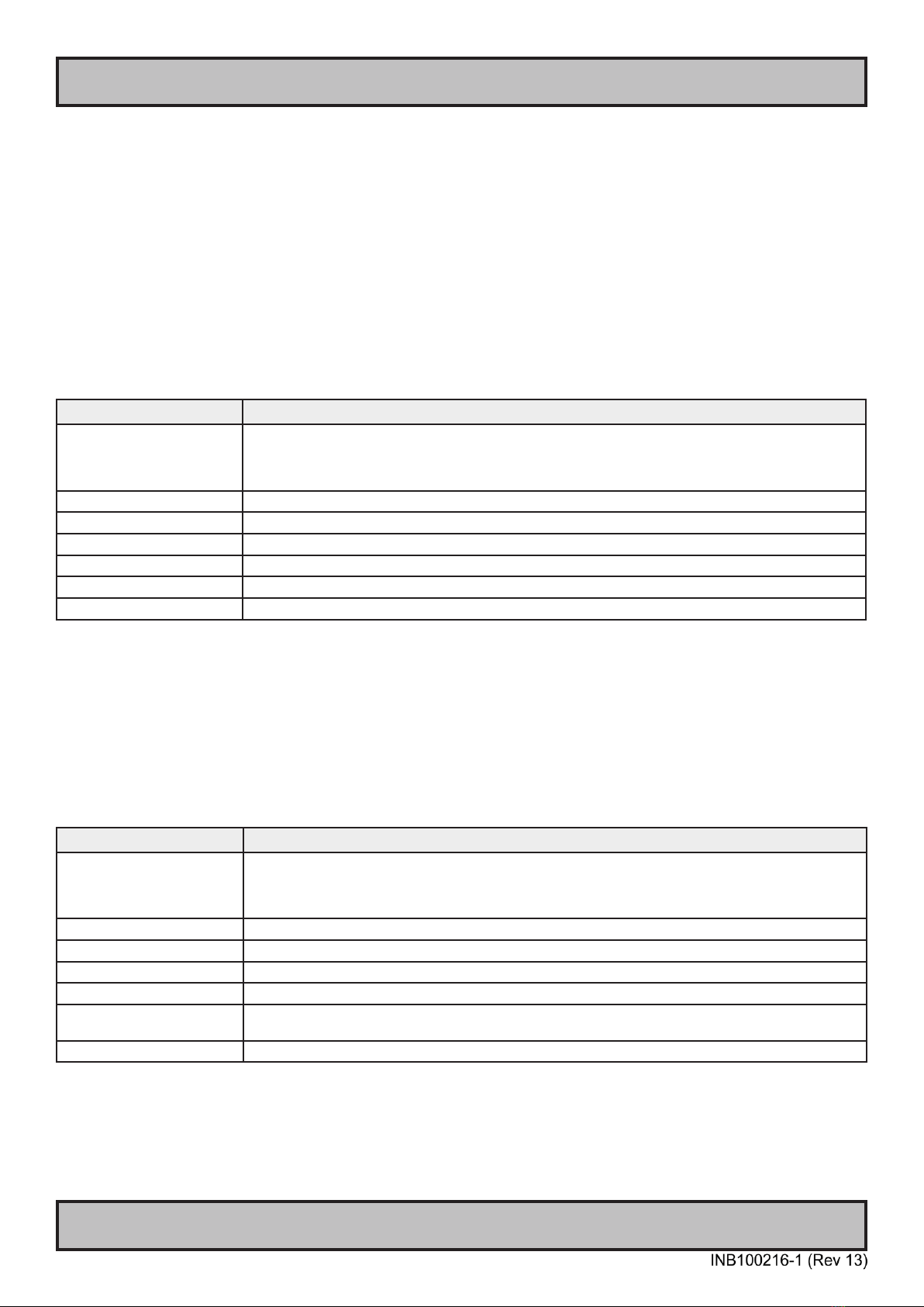
Label Size and Types
ID Label Layout Description Specication
Manufacturer: Product: 100W 115VAC/60Hz
Hatteland Display Maritime 230VAC/50Hz
NORWAY Multi
Computer Date: 20110526
Serial Number:
JH 19T14 MMC-AA1-AAAA-000256
Type : Serial Number Label
Name : Label D
Size : 75mm wide x 60mm high (square size)
Note: Text content of label will match specications
derived from Data Sheet.
Silver with glue on back, non-
tearable and made for thermal
transfer printing.
Barcode type: CODE128 (used extensively world wide in shipping and packaging
industries. The symbology was formerly dened as ISO/IEC 15417:2007.)
Type : Operating System (OS) label.
Microsoft® Windows® Embedded Enterprise only.
Size : 70mm wide x 28mm high (rectangle size)
Note: Label only present if OS was part of factory
option order. Linux OS does not have any label.
As per delivered from supplier.
Type : Touch Screen Label
Name : Label B
Size : 60mm wide x 22mm high (rectangle size)
Note: Only present if Touch Screen was part of factory
option order.
Silver with glue on back, non-
tearable and made for thermal
transfer printing.
Note: Content on label will vary based on Touch Screen type and/or Touch Screen
Controller. Label shown to the right is for illustration purposes only!
Type : Warranty Label
Size : 30mm wide x 23mm high (oval size)
Tampering proof sticker with glue
on back.
Type : Quality Control (QC) Label
Size : 30mm wide x 23mm high (oval size)
Ordinary sticker with glue on
back.
12
Product Labeling
IND100077-140
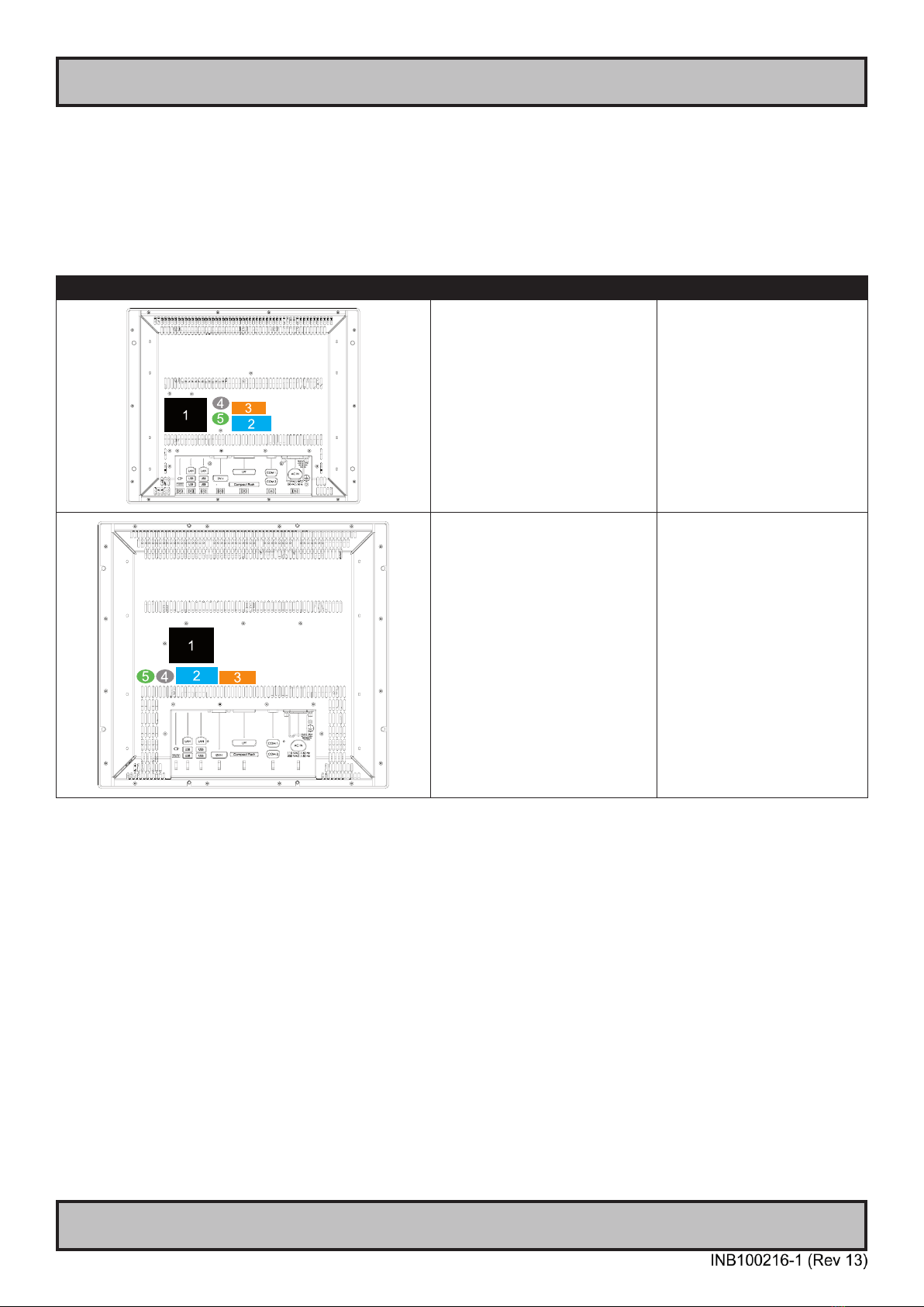
Label Locations
Number ID and coloring based on “Label Size and Types“ table from previous page. All illustrations below is seen
from rear (and side where needed) with connectors facing down. Actual labels regarding its size and text orientation
vs product size is drawn in. Due to space restrictions on selected units, some labels will be rotated 90 degrees to t
properly. The arrangement of labels may be shifted/stacked differently as it is based on factory options, such as; Touch
Screen, but they will be grouped together where possible.
Label Positions Notes Applies for Product Range
Warranty label covers screw.
Labels placed on rear.
JH 15T17 MMC-xxx-Axxx
Warranty label covers screw.
Labels placed on rear.
JH 19T14 MMC-xxx-Axxx
13
Product Labeling
IND100077-139
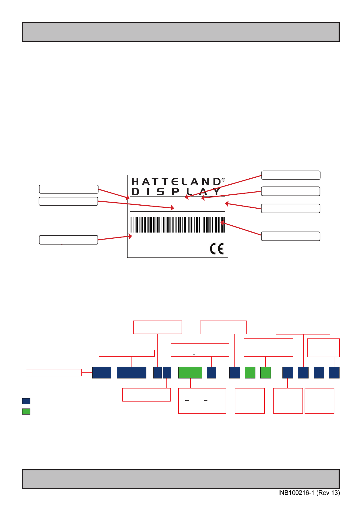
Typenumber Structure (example)
Type Number shown below may not match your actual unit, but structure ID description applies for the entire product
range. Reference: http://www.hatteland-display.com/pdink/ind100780-2.php
Serial Number Label Layout (example)
Warranty Label
If you are to perform service on a unit still under warranty, any warranty will be void if this label show signs of removal
attempts (re-gluing) or removed completely*. This label is located on the back of the product and covers a key screw.
This is to aid service departments to determine if there has been any unauthorized service on a unit still under
warranty.
*Note, however that replacing / installing additional HDD, RAM, CPU or add-on cards is not affected by this warranty.
Quality Control (QC) Label
This label indicates that the unit is produced, tested and packed according to manufacturer’s QA specications. It will
include a Personal ID and signature by the personnell responsible for approving the unit in production, test and
warehouse departments.
Manufacturer: Product: 100W 115VAC/60Hz
Hatteland Display Maritime 230VAC/50Hz
NORWAY Multi
Computer Date: 20110526
Serial Number:
JH 19T14 MMC-AA1-AAAA-000256
Manufacturer/Country
Product Description
Date of Production
Power Rating
Input Voltage
Type+Serial Number Barcode (TYP+SNO)
Series 1 Panel Computers - Typenumber Overview
Page 1 of 2
IND100780-2 - Rev 04 - 29 Sep 2011
Hatteland Display AS, Åmsosen, N-5578 Nedre Vats, Norway
Tel: (+47) 4814 2200 - mail@hatteland-display.com - www.hatteland-display.com
This document explains the type number structure for the
Hatteland Display Series 1 Maritime Multi Computer product range
- Example standard typenumber:
JH 19T14 MMC-AA1-AAAA
- Example standard description:
19.0” Maritime Multi Computer Core2Duo 1.5GHz 30GB SSD 2x1GB RAM WinOS RAL9011 AC Buttons (IP66)
= Locked elements for factory standards.
= Custom/options - Can be customized by customer.
TFT Panel Size in inches
Product Range ID
PCB Electronics
Revision ID
Abbreviation for
Maritime Multi or
reserved for customer
company name ID
Product Type ID
for Panel Computer Range
JH 19T 1MM C-
Power Input ID
AC or DC / AC & DC
Frame Color
or reserved
for customer
speci c ID
1
Standard Con gs or
reserved for customer
speci c ID
-
Frame or
Mechanical
Design ID
Optical Enhancement ID
User Control
Functionality
ID
Touch Screen
Technology ID
TFT Panel Generation
Revision ID
4 A A A A AA

14
Product Labeling
IND100077-139
Front Hatch Logo Label
The Hatteland Display MMC front frame design offers an area for customized logo hatch label. This hatch/label can be
ordered and customized with your own logo delivered from us. The hatch is IP66 rated to protect the front mounted
connector(s) behind the hatch.
The measurements are as follows.
WxH = 181.66 x 44.16mm / 7.15” x 1.74”. R4.10 - 4 places in each corner. Depth of area is 0.5mm.
15
IND100110-1
Touchscreen
Introduction to products with touch screen
Both Resistive and Capacitive touch screen solutions are used for our products. Please review specications found in
this manual or our website (www.hatteland-display.com) to nd your exact type number and then determine if it uses
Resistive or Capacitive.
Capacitive Touch screen
The glass overlay has a coating that stores the charge deposited over its surface electrically. It will not operate with
either a gloved hand or with a mechanical stylus. Capacitive touch screens operate by applying a small amount of
voltage to each corner of the touch screen. When the screen is touched by a human nger it draws a minute amount
of current to the X,Y point of contact. This location is calculated by the touch screen controller and transmitted back to
the computer connected to the touch screen controller.
CAPACITIVE - Brief Specications
Subject Details
Construction Top: ClearTek protective overcoat protects the sensors and increase durability.
Inside: Electrode X/Y grid pattern and conductive coating.
Bottom: Glass and conductive coating.
Small amount of voltage is applied to the four corners for measuring X and Y coordinates of the touch point.
Positional Accurancy Reported touch coordinates are within 1.0% of true position. (Based on viewing area dimensions)
Touch Contact Requirements 3 ms for nger input.
Enduarance Tested More than 225 million touches in one location without noticable degradation to the surface.
Cleaning Water, isopropyl, alcohol, and similar non-abrasive cleaners.
Liquid Resistance Liquids on screen does not impede touchscreen performance.
Light Transmission Up to 88% at 550 nm; dependant on specic surface nish chosen.
Resistive Touch screen
It generally uses a display overlay composed of layers, each with a conductive coating on the interior surface. Special
separator “dots” are distributed evenly across the active area and separate the conductive interior layers. The
pressure from using either a mechanical stylus or nger produces an internal electrical contact at the “action point”
which supplies the controller with vertical and horizontal analog voltages for data input. The resistive touch screens
are anti-glare to reduce reective shine intensity, which will slightly diffuse the light output throughout the screen.
Resistive technology activation can be initiated by; a gloved hand, ngernail, mechanical stylus or an ungloved nger.
RESISTIVE - Brief Specications
Subject Details
Construction Top: Polyester with outside hard-surface coating with clear or anti-glare nish.
Inside: Transparent conductive coating.
Bottom: Glass substrate with uniform conductive coating.
Top and bottom layers separated by separator dots.
Positional Accurancy Standard deviation of error is less than +- 0.080-inch (2mm).
Touch Activation Force Typically 57 to 133 g
Expected Life Performance More than 35 million touches in one location without failure, using a stylus similar to a nger.
Cleaning Water, isopropyl, alcohol, and similar non-abrasive cleaners.
Chemical Resistance
(Exposed for one hour)
Acetone, Common food and beverages, Hexane, Isopropyl alcohol, Methylene chloride, Methyl ethyl ketone,
Mineral spirits, Turpentine
Light Transmission Typically 75% over visible light spectrum.
Touch screen products
16
IND100110-11
Touch screen
Touch screen products
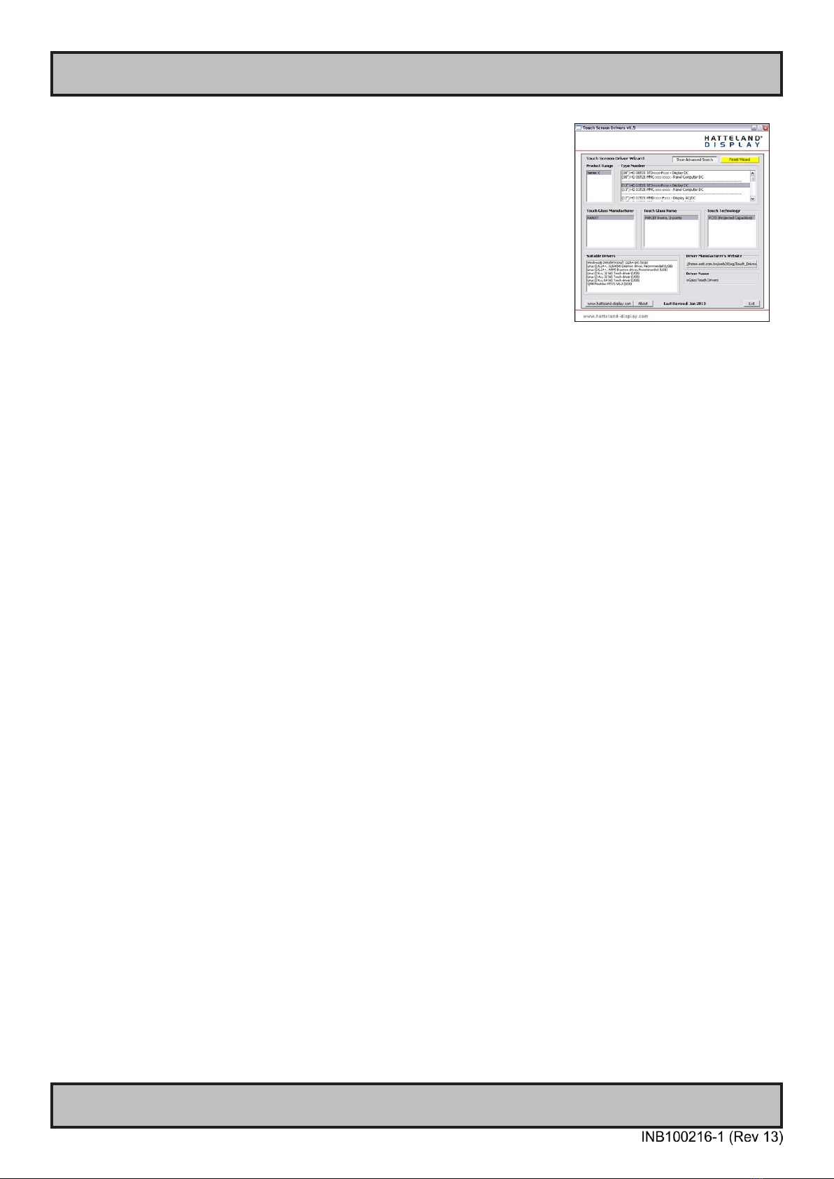
Touch Screen Drivers and Documentation
All units are shipped with a Documentation and Drivers DVD or CD which
contains suitable drivers for touch screens. (Named MEDIA STD01).
You can also visit our website www.hatteland-display.com to view the same
list (or even recently new added products) for our models with touch screen.
Before using the touch screen, it should be calibrated for your system.
Please install the 3rd party software and use the Calibrate function.
For additional touch controller/screen documentation and updated drivers, please
visit the 3rd party manufacturer website as found in the Touch Screen Wizard CD
menu.

17
Installation

18
IND100078-24
Installation
Installation and mounting
1. Most of our products are intended for various methods of installation or mounting (panel mounting, bracket
mounting, ceiling/wall mounting etc.); for details, please see the relevant mechanical drawings.
2. Adequate ventilation is a necessary prerequisite for the life of the product. The air inlet and outlet openings must
denitely be kept clear; coverings which restrict ventilation are not permissible.
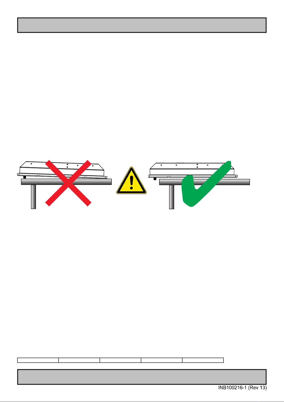
3. Generally, do not install the unit in a horizontal position (laying down), as this will cause heat to build up inside the
unit which will damage the LCD Panel. To prevent this problem we recommend installing the unit in a vertical
position (±30 degrees) to improve the airow through the unit.
4. To further improve the cooling of the unit we recommend installing Cooling Fans underneath blowing upwards into
the unit air inlet. This may be required in high temperature applications and also when there is reason to expect
temperature problems due to non-optimal way of mounting.
5. Exposure to extreme direct sunlight can cause a considerable increase in the temperature of the unit, and might
under certain circumstances lead to overtemperature. This point should already be taken into consideration when
the bridge equipment is being planned (sun shades, distance from the windows, ventilation, etc.)
6. Space necessary for ventilation, for cable inlets, for the operating procedures and for maintenance, must be
provided.
7. If the push buttons of the product are not illuminated, an external, dimmable illumination (IEC 60945 Ed. 4, 4.2.2.3,
e.g. Goose neck light) is required for navigational use. The illumination shall be dazzle-free and adjustable to
extinction.
8. Information about necessary pull-relievers for cables is indicated in the Physical Connection section of this manual.
Attention must be paid to this information so that cable breaks will not occur, e.g. during service work.
9. Do not paint the product. The surface treatment inuences on the excess heat transfer. Painting, labels or other
surface treatments that differ from the factory default, might cause overheating.
10. Expose to heavy vibration and acoustic noise might under certain circumstances affect functionality and expected
lifetime. This must be considered during system assembly and installation. Mounting position must carefully be
selected to avoid any exposure of amplied vibration.
General mounting instructions
1. The useful life of the components of all Electronics Units generally decreases with increasing ambient temperature;
it is therefore advisable to install such units in air-conditioned rooms. If there are no such facilities these rooms
must at least be dry, adequately ventilated and kept at a suitable temperature in order to prevent the formation of
condensation inside the display unit.
2. With most Electronic Units, cooling takes place via the surface of the casing. The cooling must not be impaired by
partial covering of the unit or by installation of the unit in a conned cabinet.
3. In the area of the wheel house, the distance of each electronics unit from the magnetic standard compass or the
magnetic steering compass must not be less than the permitted magnetic protection distance. This distance is
measured from the centre of the magnetic system of the compass to the nearest point on the corresponding unit
concerned.
4. Units which are to be used on the bridge wing must be installed inside the “wing control console” protected against
the weather. In order to avoid misting of the viewing screen, a 25 ... 50 W console-heating (power depending on the
volume) is recommended.
5. When selecting the site of a display unit, the maximum cable lengths have to be considered.
General Installation Recommendations
19
IND100078-24
General Installation Recommendations
Installation
6. When a product is being installed, the surface base or bulkhead must be checked to ensure that it is at in order to
avoid twisting of the unit when the xing screws are tightened, because such twisting would impair mechanical
functions. Any unevenness should be compensated for by means of spacing-washers.
7. This Product shall be grounded to protective Earth. For AC Power cables this is done trough the ground wire in the
connector, for DC input the ground bolt shall be used. A shorter and thicker cable gives better grounding. A 6mm²
is Recommended, but a 4mm² or even 2.5mm² can be used for this purpose.
8. Transportation damage, even if apparently insignicant at rst glance, must immediately be examined and be
reported to the freight carrier. The moment of setting-to-work of the equipment is too late, not only for reporting the
damage but also for the supply of replacements.
9. The classication is only valid for approved mounting brackets provided by Hatteland Display. The unit shall be
mounted stand-alone without any devices or loose parts placed at or nearby the unit. Any other type of mounting
might require test and re-classication.
Brightness knob precaution
Applies for models with potmeter knob. Please be aware of the risk of breaking or bending the brightness knob. The
brightness knob should be free of any obstruction.
Ergonomics
1. Adjust the unit height so that the top of the screen is at or below eye level. Your eyes should look slightly
downwards when viewing the middle of the screen.
2. Adjust screen inclination to remain gaze angle to the centre of the screen approximately perpendicular to the line of
gaze.
3. When products are to be operated both from a sitting position and from a standing position, a screen inclination of
about 30° to 40° (from a vertical plane) has turned out to be favourable.
4. The brightness of displays is limited. Sunlight passing directly through the bridge windows - or its reection - which
falls upon the screen workplaces must be reduced by suitable means (negatively inclined window surfaces,
venetian blinds, distance from the windows, dark colouring of the deckhead). However, Series 1 can be offered
with optical enhanced technology to reduce reections and are viewable in direct sun light, but as a general rule
the units at the bridge wing area is recommended to be installed or mounted by suitable alignment or bulkhead /
deckhead mounting in such a way that reections of light from the front pane of the display are not directed into the
observer’s viewing direction.
5. The use of ordinary commercial lter plates or lter lms is not permitted for items of equipment that require
approval (by optical effects, “aids” of that kind can suppress small radar targets, for example).
6. For ECDIS applications, the minimum recommended viewing distance are as follows:
(IEC62288, Part 7.5 Screen resolution)
19 inch = 1011mm
20
IND100078-24
General Installation Recommendations
Installation
Cables
Use only high quality shielded signal cables.
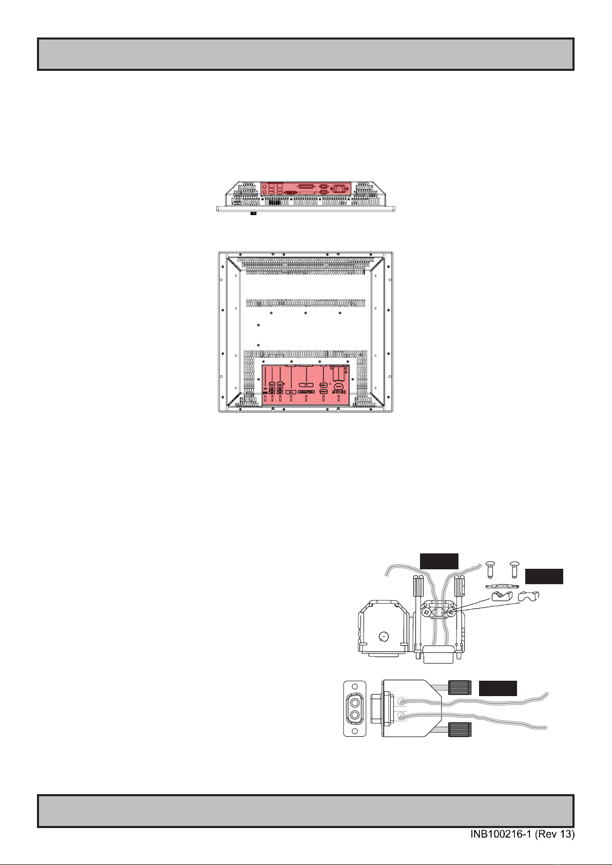
Cable Entries & Connectors (Marked area) - Illustration only
Bottom View
Back View
Maximum Cable Length
Any cable should generally be kept as short as possible to provide a high quality input/output. The maximum signal
cable length will depend on the signal resolution and frequency, but also on the quality of the signal output from the
computer/radar.
Conguring DC power input housing connector
Note: Only applicable for DC models!
For installations that require DC power input, use the provided
2-pin DC Power Input housing with internal cable screw terminal.
1: Open the housing
2: Unmount the fasteners. (FIG 1)
3: Mount power cables to screw terminal (FIG 2). Note polarity!
4: Secure the cable tightly with fasteners (FIG 3, FIG 1)
5: Close the housing
Note: Please check polarity before connecting any cables
to the screw terminal. Screw terminal
FIG 1
FIG 2
FIG 3
+ -
+ -
+
-
This manual suits for next models
1
Table of contents
Other Hatteland Desktop manuals

Hatteland
Hatteland HT C01 Series User manual

Hatteland
Hatteland HT 403XE STD User manual

Hatteland
Hatteland HT 405P4 STD User manual

Hatteland
Hatteland JH 23T02 MMC User manual

Hatteland
Hatteland HT 416 User manual

Hatteland
Hatteland HT B17 Series User manual

Hatteland
Hatteland HT 205P4 STD User manual

Hatteland
Hatteland HT B17 Series User manual

Hatteland
Hatteland HT 221 User manual

Hatteland
Hatteland 1 Series User manual


