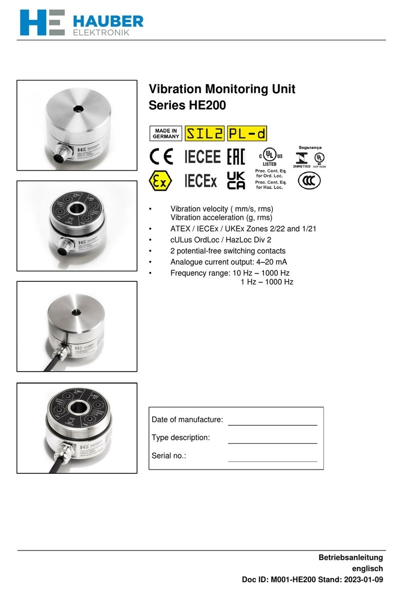
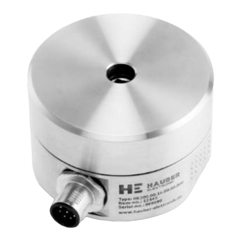
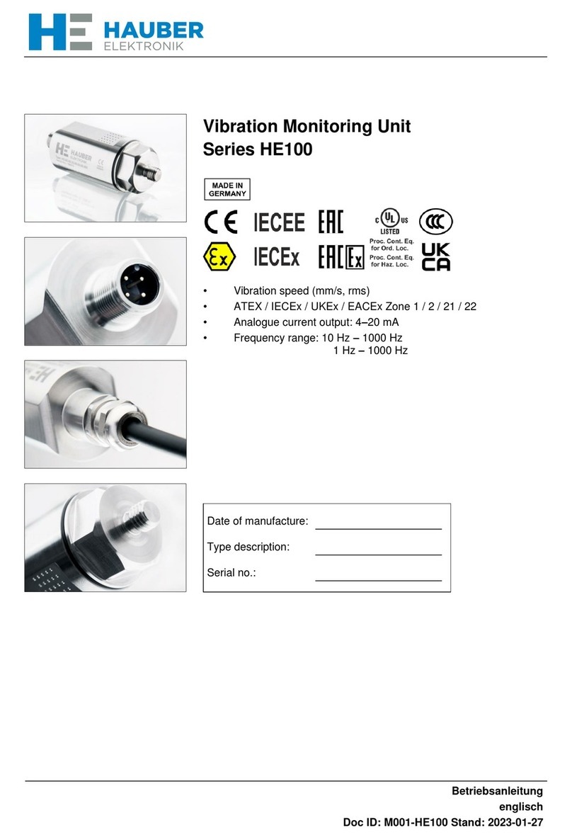
Hauber Elektronik HE205 Series User manual

Betriebsanleitung
englisch
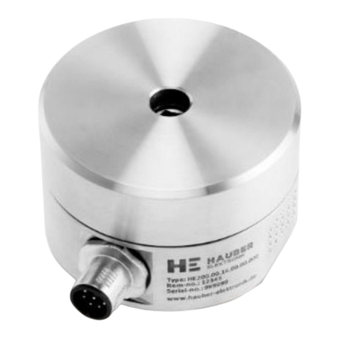
Vibration Monitoring Unit
Series HE205
IECEE
IECEx
•Vibration acceleration (g rms)
•ATEX / IECEx / EACEx Zone 2 / 22 and 1 / 21
•cULus OrdLoc / HazLoc Div 2
•2 potential-free switching contacts (Window
function)
•Analogue current output: 4–20 mA
•Frequency range: 10 Hz –1000 Hz
1 Hz –1000 Hz
Date of manufacture:
Type description:
Serial no.:

HAUBER-Elektronik GmbH
Operating instructions
Vibration Monitoring Unit
Type HE205
Standard and ATEX / IECEx / EACEx
HE205
Version: 2021-02-05
Attention!
Prior to commissioning the product, the instruction manual must be read and
understood.
All rights reserved, including rights to translation.
Subject to modifications.
Please contact the company with any questions:
HAUBER-Elektronik GmbH
Fabrikstraße 6
D-72622 Nürtingen
Germany
Tel.: +49 (0) 7022 / 21750-0
Fax: +49 (0) 7022 / 21750-50
info@hauber-elektronik.de
www.hauber-elektronik.de

HAUBER-Elektronik GmbH
3
1 Contents
1Contents...................................................................................................................................................3
2Safety information....................................................................................................................................4
2.1 General .................................................................................................................................................4
2.2 Symbols used .......................................................................................................................................4
3Scope of this instruction manual..............................................................................................................5
4Vibration monitoring HE205.....................................................................................................................5
5Intended Use............................................................................................................................................5
6Scope of supply .......................................................................................................................................5
7Documents and Certificates.....................................................................................................................6
8Transfer of liability when operating in potentially explosive atmospheres...............................................6
9Overview of application areas..................................................................................................................7
10 Example labels.........................................................................................................................................9
11 Information on the cULus validity range ................................................................................................10
12 Functional safety instructions ................................................................................................................11
12.1 Safety level / key indicators ................................................................................................................11
12.2 General notes .....................................................................................................................................11
12.3 Instructions for the Fail Safe State......................................................................................................11
13 Technical data........................................................................................................................................12
13.1 General data.......................................................................................................................................12
13.2 Electrical data .....................................................................................................................................12
13.3 Operating range of the vibration monitoring unit ................................................................................13
13.4 Typical frequency response................................................................................................................14
13.5 Mechanical data..................................................................................................................................15
13.6 Housing dimensions............................................................................................................................15
14 Connection.............................................................................................................................................16
15 Functional description............................................................................................................................17
15.1 Operating conditions...........................................................................................................................17
15.2 Alarm and limit setting ........................................................................................................................18
15.3 Limit values and delay times...............................................................................................................19
16 Assembly and disassembly ...................................................................................................................21
16.1 General notes .....................................................................................................................................21
16.2 Fixing the vibration monitoring unit to the mounting surface..............................................................21
16.3 Tamper protection...............................................................................................................................22
17 Installation and commissioning..............................................................................................................23
17.1 General notes .....................................................................................................................................23
18 Maintenance and repair.........................................................................................................................25
18.1 General notes .....................................................................................................................................25
18.2 Troubleshooting Table........................................................................................................................25
19 Transport, storage and disposal ............................................................................................................26
20 Coding HE205........................................................................................................................................27
21 EU declaration of conformity..................................................................................................................28
HAUBER-Elektronik GmbH
4
2 Safety information
2.1 General
The safety instructions are intended to protect people and property from damage and hazards
that could arise as the result of improper use, incorrect operation or other misuse or devices,
especially in explosive areas. Therefore, please read the operating instructions carefully before
working on the product or operating it. The operating instructions must be accessible to
operating personnel at all times.
Please make sure that all documents are present and complete before commissioning or
performing other work on the product. If the documents have not all been delivered in full or if
further copies are necessary, they can also be obtained in other languages.
The product is built according to the latest state of the art. However, hazards to people,
machinery and systems can still arise as the result of improper handling, unintended use or
operation and maintenance by persons inadequately trained on the product.
All those who are involved in the installation, operation and maintenance of the product in the
operator’s plant must read and understand the operating instructions.
The product may only be assembled, disassembled, installed and repaired by instructed,
sufficiently trained and authorised personnel.
2.2 Symbols used
This symbol indicates an explosion hazard.
This symbol indicates a hazard from electrical current.
This symbol indicates safety-related information.
This symbol indicates information unrelated to safety.

HAUBER-Elektronik GmbH
5
3 Scope of this instruction manual
This instruction manual for the HE205-type vibration monitoring unit applies to the following
versions:
HE205.00, HE205.02 and HE205.01
The variants are functionally identical. The variants HE205.02 and HE205.01 have
additional certifications and labels which permit use in potentially exclusive atmospheres.
4 Vibration monitoring HE205
The HE205 type vibration monitoring unit is used to measure and monitor the vibration
acceleration of machinery. It offers the following features:
•Two limit values and associated delay timings can be adjusted separately.
•The two potential-free switching contacts will signal any exceeding of the relevant defined
limit values. This can be used to generate an alarm.
•Measurement parameter: vibration acceleration (g rms).
•Analogue current output: Interference-free DC signal from 4-20 mA, proportional to the
measuring range of the monitoring unit.
•A break on the monitoring cable can be detected by the subsequent evaluation device:
DC signal value < 3.5 mA.
5 Intended Use
The HE205 is used to protect machines and mechanical equipment against undue strong
vibrations. It may only be used in accordance with the specifications listed in the data sheet. It is
used exclusively for measuring mechanical vibrations.
Main fields of application: Conveyors, screening equipment, drying and cooling equipment and
similar oscillating mechanical equipment.
If the equipment is used in a manner not specified by the manufacturer, the
protection provided by the equipment may be impaired.
6 Scope of supply
All versions include:
•Vibration monitoring
•Cylinder head screw with hex socket, M8 x 20 mm
•Spring washers for M8
•Seal label
•Operating instructions

HAUBER-Elektronik GmbH
6
7 Documents and Certificates
You can find the following documents and certificates for HE205 type at www.hauber-
elektronik.de where they can be viewed and downloaded:
•EU type examination certificate ATEX, no.: UL 20 ATEX 2421X
•EU type examination certificate IECEx, no.: IECEx ULD 20.0022X
•EACEx certificate, No.: %PLACEHOLDER%
•EAC Declaration
•Functional safety certificate (SIL 2)
•Safety manual SIL2
8 Transfer of liability when operating in potentially explosive atmospheres
The owner of the system is exclusively liable for the appropriate configuration of the electrical
connections with respect to explosion protection regulations and correct commissioning.
If the system is installed by a sub-contractor on behalf of the owner, the system may only be
commissioned after the sub-contractor has issued written confirmation in the form of a certificate
of installation that the system has been installed correctly and professionally in accordance with
the applicable legal regulations.
The operator is obliged to notify the responsible authorities of the initial commissioning of
explosion-protected systems or system components and their re-commissioning following
extensive changes or maintenance.

HAUBER-Elektronik GmbH
7
9 Overview of application areas
Version
1
2
3
4
5
6
Coding
HE205.00.xx.xx.xx.00.xxx
HE205.00.xx.xx.xx.01.xxx
HE205.02.xx.xx.xx.00.xxx
HE205.02.xx.xx.xx.01.xxx
HE205.01.xx.xx.xx.00.xxx
HE205.01.xx.xx.xx.02.xxx
Connection
M12 connector
x
x
Integrated cable
x
x
x
x
Measuring head temperature TM
Ambient temperature TA
Limitation for application area
cULus:
-30 °C ≤ TM≤ 80 °C
-30 °C ≤ TA≤ 60 °C
-40 °C ≤ TM≤ 85 °C
-40 °C ≤ TA≤ 60 °C
x
x
x
-35 °C ≤ TM≤ 125 °C
-35 °C ≤ TA≤ 60 °C
x
x
-20 °C ≤ TM≤ 125 °C
-20 °C ≤ TA≤ 60 °C
x
IEC
x
x
x
x
x
x
Proc. Cont. Eq. Ord. Loc
E507077
x
x
x
x
Ex Zone 2 and 22
II 3G Ex ec IIC T4 Gc
II 3D Ex tc IIIC 135°C Dc
UL 20 ATEX 2421 Rev. 0X
x
x
IECEx
Ex ec IIC T4 Gc
Ex tc IIIC 135°C Dc
IECEx ULD 20.0022 Issue 0X
x
x
Proc. Cont. Eq. Haz. Loc.
Class I, Division 2, Groups A, B, C and D, T4
Class II, Division 2 Groups F and G, T4
E507077
x
x
?
?
x
x
Segurança
OCP-0029
Ex ec IIC T4 Gc
Ex tc IIIC 135°C Dc
UL-BR 20.1667X
x
x
CCC
?
?
x
x
Ex Zone 1 and 21
II 2G Ex db IIC T4 Gb
II 2D Ex tb IIIC 135°C Db
UL 20 ATEX 2421 Rev. 0X
x
x
IECEx
Ex db IIC T4 Gb
Ex tb IIIC 135°C Db
IECEx ULD 20.0022 Issue 0X
x
x
?
?
x
x
Segurança
OCP-0029
Ex db IIC T4 Gb
Ex tb IIIC 135°C Db
UL-BR 20.1667X
x
x
CCC
?
?
x
x

HAUBER-Elektronik GmbH
8

HAUBER-Elektronik GmbH
9
10 Example labels
Variant 1 - HE205.00.xx.xx.xx.00.000
Variant 2 - HE205.00.xx.xx.xx.01.xxx
Variant 3 - HE205.02.xx.xx.xx.00.000
Variant 4 - HE205.02.xx.xx.xx.01.xxx
Variant 5 - HE205.01.xx.xx.xx.00.xxx
Variant 6 - HE205.01.xx.xx.xx.02.xxx

HAUBER-Elektronik GmbH
10
11 Information on the cULus validity range
In order to install the device according to the UL/CSA/IEC standard, the following information
must be observed.
Electrical protection
Devices must be protected by means of fuses, circuit breakers, overheating
protection, impedance-limiting switches or similar to ensure protection against
excessive power output if there is a fault in the device. Protection must be
applied to supply lines and switching lines.
A circuit breaker suitable for 30V/3A according to UL Standard 489/CSA
Standard (C22.2) no. 5/IEC 60947-2 must be installed near the device.
A fuse suitable according to UL Standard 248/CSA Standard (C22.2) no.
248/IEC 60127 must be installed near the device. The fuse must have a slow
triggering characteristic (“T”).
Limited temperature range
The following temperature ranges apply for variants with integrated cable:
Measuring head
temperature
-30 °C ≤ TM≤ +80° C
Ambient temperature
-30 °C ≤ TAmb ≤ +60° C

HAUBER-Elektronik GmbH
11
12 Functional safety instructions
12.1 Safety level / key indicators
The HE205 vibration monitoring hardware was tested by TÜV Süd. The results meet the criteria
according to SIL2 and Pl-d.
Safety marking placeholder1
….
Safety marking placeholder2
….
12.2 General notes
A reboot of the vibration monitoring unit must be performed annually in order to
test the switching of potential-free switching contacts.
12.3 Instructions for the Fail Safe State
When the power supply is switched on, the vibration monitoring unit will perform a self-test.
During operation, self-tests are performed automatically in cycles. If a self-test fails, the vibration
monitoring unit switches to the Fail Safe State.
In the Fail Safe State all status LEDs are lit, all potential-free switching contacts are open and
the analogue current output supplies 0 mA.

HAUBER-Elektronik GmbH
12
13 Technical data
13.1 General data
Each sensor has one of the listed measuring and frequency ranges. Further
ranges on request.
Please indicate the measuring and frequency range in your request.
Measuring range:
0 –1 g rms
0 –2 g rms
0 –4 g rms
0 –6 g rms
0 –8 g rms
0 –10 g rms
Measuring accuracy:
± 10% (as per DIN ISO 2954)
Transverse sensitivity:
< 5%
Frequency range:
10 Hz–1,000 Hz (standard)
1 Hz–1000 Hz
Calibration point:
159.2 Hz and 90% amplitude of measuring range
Maximum acceleration:
±16.5 g
Lifetime:
10 years
MTTF value:
%placeholder%
Tab. 1: General data
13.2 Electrical data
Output signal:
1 x 4-20 mA (proportional to the measuring range)
Switching contact:
2 x potential-free switching contacts (pre- and main alarm)
Switching contact switching
load:
1A / 30 V DC
Power supply:
24 V DC ± 10%
Power input (max.):
100 mA
Load/output load (max.):
500 Ω
Automatic:
As soon as the vibration values fall below the limit values, the
potential-free switching contacts automatically re-energize.
Tab. 2: Electrical data

HAUBER-Elektronik GmbH
13
13.3 Operating range of the vibration monitoring unit
The operating range is independent from the measuring range. It can be derived from the
maximum acceleration, which is 16.5 g across all frequencies. The maximum measurable
vibration velocity is based on the formula
For sinusoidal vibration,
applies
Fig. 1: shows the operating range of the vibration monitoring unit, which is limited by the
maximum measurable vibration velocity in mm/s depending on the frequency in Hz.
Fig. 1: Operating range diagram
1 Frequency in Hz
2 Vibration velocity in mm/s
3 Operating range of the vibration monitoring unit
Reading example:
Frequency
(Hz)
Maximum measurable
Vibration velocity
(mm/s)
250
103
400
64
1000
25
Tab. 3: Reading example of operating range
0
20
40
60
80
100
120
140
160
180
200
0100 200 300 400 500 600 700 800 900 1000
2→
1→
3

HAUBER-Elektronik GmbH
14
13.4 Typical frequency response
10 Hz–1,000 Hz (standard)
The frequency response is recorded using a reference sensor.
• 4 Hz. . . 1200 Hz acceleration sensor
Fig. 2: Typical frequency response 10 Hz–1000 Hz
1 Frequency in Hz
2 Amplification in dB
1 Hz–1000 Hz
The frequency response is recorded using two reference sensors.
• 1 Hz. . . 10 Hz laser sensor
• 10 Hz. . . 1200 Hz acceleration sensor
Fig. 3: Typical frequency response 1 Hz–1000 Hz
1 Frequency in Hz
2 Amplification in dB

HAUBER-Elektronik GmbH
15
13.5 Mechanical data
For more information see Section "Coding" on page 27.
Housing material:
Stainless steel V2A, material no.: 1.4305 (standard)
Fastening:
Cylinder head Allen screw M8 x 20 mm
Thread pitch: 1.25 mm (standard)
Mounting:
Housing must be earthed via the M8 fastening
Cover tightening torque
5 Nm
Measuring direction:
Along the fastening axis
Weight:
approx. 500 g
Protection class:
Cover and plug connection closed:
IP 66/67
NEMA Type 4X Enclosure
Product is suitable for outdoor applications
Max. humidity:
100%
Tab. 4: Mechanical data
13.6 Housing dimensions
Fig. 4: Housing with M12 connector
Fig. 5: Housing with
integrated cable
All measurements
in mm
1 M12 connector
2 Measuring direction
1 Cable gland
2 Connecting cable
3 Measuring direction

HAUBER-Elektronik GmbH
16
14 Connection
Version:
M12 connector
Pin 1:
24 V DC
Pin 2:
GND
Pin 3:
4-20 mA output signal
Pin 4:
NC (Not connected)
Pin 5:
Potential-free switching contact 1
Pin 6:
Potential-free switching contact 1
Pin 7:
Potential-free switching contact 2
Pin 8:
Potential-free switching contact 2
Version:
Integrated cable
Pin 1:
white
24 V DC
Pin 2:
brown
GND
Pin 3:
green
4-20 mA output signal
Pin 4:
yellow
NC (Not connected)
Pin 5:
grey
Potential-free switching contact 1
Pin 6:
pink
Potential-free switching contact 1
Pin 7:
blue
Potential-free switching contact 2
Pin 8:
red
Potential-free switching contact 2
Fig. 6: Wiring diagram
The wiring diagram shows the alarm status or the current status!
Potential-free switching contacts 1 and 2 are open.

HAUBER-Elektronik GmbH
17
15 Functional description
In an explosive atmosphere the vibration monitoring unit HE205 will only be
opened in a de-energized state.
The type HE205 is used for monitoring vibration acceleration.
If the acceleration value is below or above the adjustable window area,
an alarm will be triggered. The vibration monitoring contains two channels independent from
each other, LIM1 and LIM2. The lower limit value of the window area is adjusted on LIM1 and
the upper limit value is adjusted on LIM2 (see chart).
The HE205 type also has an analogue current output. This supplies direct current of 4-20 mA
proportional to the vibration amplitude.
Fig. 7: Window function
1 Alarm for values below LIM1
2 Window area
3 Alarm for values above LIM2
15.1 Operating conditions
Operating state
Reading
Switching
contacts
LED status
OK
Within limit values
Closed
green
WARNING
Outside of limit values, delay
time runs
Closed
green + yellow
ALARM
Outside of limit values, delay
time expired
Open
red
Fail Safe State
0 mA
Open
red + yellow + green
De-energized
0 mA
Open
All LEDs off
Tab. 5: Operating conditions

HAUBER-Elektronik GmbH
18
15.2 Alarm and limit setting
By pressing the "Save Config" button, the current configuration is displayed by the LEDs around
the HEX switches. For further information, see chapter "Limit values and delay times” on page
19.
The limit values and delay times are calibrated using the respective HEX switch. As soon as a
switch position is changed, the LEDs around the Hex switch start to blink. The number of
blinking LEDs represents the current position of the HEX switch. To save the configuration,
press and hold down the "Save Config" button for three seconds. Acceptance of the
configuration is signalled by steady lighting up of the LEDs in the selected HEX switch position.
After about five minutes the LEDs turn off automatically.

HAUBER-Elektronik GmbH
19
15.3 Limit values and delay times
SET
Position
Limit values (g)
Measuring
range
0-1 g
0-2 g
0-4 g
0-6 g
0-8 g
0-10 g
0
0
0
0
0
0
0
1
0.063
0.125
0.25
0.375
0.5
0.625
2
0.125
0.25
0.5
0.75
1
1.25
3
0.188
0.375
0.75
1.125
1.5
1.875
4
0.25
0.5
1
1.5
2
2.5
5
0.313
0.625
1.25
1.875
2.5
3.125
6
0.375
0.75
1.5
2.25
3
3.75
7
0.438
0.875
1.75
2.625
3.5
4.375
8
0.5
1
2
3
4
5
9
0.563
1.125
2.25
3.375
4.5
5.625
10
0.625
1.25
2.5
3.75
5
6.25
11
0.688
1.375
2.75
4.125
5.5
6.875
12
0.75
1.5
3
4.5
6
7.5
13
0.813
1.625
3.25
4.875
6.5
8.125
14
0.875
1.75
3.5
5.25
7
8.75
15
0.938
1.875
3.75
5.625
7.5
9.375
The SET rotary button has 16 positions, representing the limit value of an alarm. The
measuring range of the vibration monitoring unit is divided into 16 linear steps.
In general:
Example: Limit setting
Measuring range:
0–4 g
SET rotary button Pos.:
8 (9)
Limit value:
2 g (2.25 g)
Delay times
TIME Position
0
1
2
3
4
5
6
7
8
9
10
11
12
13
14
15
Delay time
(secs)
0
1
2
3
4
5
7.5
10
12.5
15
17.5
20
25
30
45
60
Tab. 6: Delay times

HAUBER-Elektronik GmbH
20
Table of contents
Other Hauber Elektronik Measuring Instrument manuals

Hauber Elektronik
Hauber Elektronik HE250 Series User manual

Hauber Elektronik
Hauber Elektronik HE200 Series User manual

Hauber Elektronik
Hauber Elektronik HE050 Series User manual

Hauber Elektronik
Hauber Elektronik HE255 Series User manual

Hauber Elektronik
Hauber Elektronik HE100 Series User manual

Hauber Elektronik
Hauber Elektronik HE050 Series User manual

Hauber Elektronik
Hauber Elektronik HE103 Series User manual