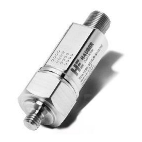
Hauber Elektronik HE050 Series User manual

Betriebsanleitung
englisch
Doc ID: M001-HE050 Stand: 2023-03-28
Vibration Monitoring Unit
Series HE050
•Vibration speed (mm/s, rms)
•Vibration acceleration (g, rms)
•Vibration acceleration (g, peak)
•Temperature (°C)
•Output 1: IO link or
digital switching output
•Output 2: Analogue current output 4-20 mA or
digital switching output
•Configurable frequency range: 10-1000 Hz
Date of manufacture:
Type description:
Serial no.:

HAUBER-Elektronik GmbH
Operating instructions
Vibration Monitoring Unit
Type HE050
HE050
Version: 2023-03-28
Attention!
Prior to commissioning the product, the instruction manual must be read and un-
derstood.
All rights reserved, including rights to translation.
Subject to modifications.
Please contact the company with any questions:
HAUBER-Elektronik GmbH
Fabrikstraße 6
D-72622 Nürtingen
Germany
Tel.: +49 (0) 7022 / 21750-0
Fax: +49 (0) 7022 / 21750-50
info@hauber-elektronik.de
www.hauber-elektronik.de

HAUBER-Elektronik GmbH
3
1 Contents
1Contents...................................................................................................................................................3
2Safety information....................................................................................................................................4
3Scope of this instruction manual..............................................................................................................4
4Vibration Monitoring Unit Type HE050 ....................................................................................................5
5Intended Use............................................................................................................................................5
6Scope of supply .......................................................................................................................................5
7Documents and Certificates.....................................................................................................................5
8Fields of application and example labels.................................................................................................6
9Information on the cULus validity range ..................................................................................................6
10 Technical data..........................................................................................................................................7
10.1 General data.........................................................................................................................................7
10.2 Electrical data .......................................................................................................................................8
10.3 Operating range of the vibration monitoring unit ..................................................................................9
10.4 Typical frequency response................................................................................................................10
10.5 Housing dimensions............................................................................................................................10
10.6 Mechanical data..................................................................................................................................11
11 Connection.............................................................................................................................................11
12 IO-Link description of functionality.........................................................................................................12
12.1 Introduction.........................................................................................................................................12
12.2 Software-parameterization service.....................................................................................................12
12.3 General data.......................................................................................................................................12
12.4 Measured values and process values ................................................................................................12
12.5 Outputs ...............................................................................................................................................12
12.6 Switching signal..................................................................................................................................13
12.7 Frequency ranges (Filter settings)......................................................................................................13
12.8 Maintenance Data...............................................................................................................................13
13 Installation and commissioning..............................................................................................................14
13.1 General notes .....................................................................................................................................14
13.2 Wiring diagram / earthing concept......................................................................................................14
14 Assembly and disassembly....................................................................................................................15
14.1 General notes .....................................................................................................................................15
14.2 Fixing the vibration monitoring unit to the mounting surface..............................................................15
15 Accessories............................................................................................................................................16
16 Maintenance and repair.........................................................................................................................17
16.1 General notes .....................................................................................................................................17
16.2 Troubleshooting Table........................................................................................................................17
17 Coding HE050........................................................................................................................................18
18 Transport, storage and disposal ............................................................................................................19
19 EU declaration of conformity..................................................................................................................19

HAUBER-Elektronik GmbH
4
2 Safety information
2.1 General
The safety instructions are intended to protect people and property from damage and hazards
that could arise as the result of improper use, incorrect operation or other misuse or devices,
especially in explosive areas. Therefore, please read the operating instructions carefully before
working on the product or operating it. The operating instructions must be accessible to operat-
ing personnel at all times.
Please make sure that all documents are present and complete before commissioning or per-
forming other work on the product. If the documents have not all been delivered in full or if fur-
ther copies are necessary, they can also be obtained in other languages.
The product is built according to the latest state of the art. However, hazards to people, machin-
ery and systems can still arise as the result of improper handling, unintended use or operation
and maintenance by persons inadequately trained on the product.
All those who are involved in the installation, operation and maintenance of the product in the
operator’s plant must read and understand the operating instructions.
The product may only be assembled, disassembled, installed and repaired by instructed, suffi-
ciently trained and authorised personnel.
2.2 Symbols used
This symbol indicates a hazard from electrical current.
This symbol indicates safety-related information.
This symbol indicates information unrelated to safety.
3 Scope of this instruction manual
This instruction manual for the HE050-type vibration monitoring unit applies to all variants of the
HE050.

HAUBER-Elektronik GmbH
5
4 Vibration Monitoring Unit Type HE050
Vibration monitoring unit type HE050 is a sensor that measures the vibration speed, vibration
acceleration and temperature and can be used for purposes such as monitoring the absolute
bearing vibrations of machinery in line with DIN ISO 10816. It offers the following features.
•Two freely configurable outputs
•Output 1: IO link or digital switching output
•Output 2: Analogue current output (4-20 mA) or digital switching output
•Configurable frequency range 10 Hz–1000 Hz. For all possible frequency ranges see
"Frequency ranges (Filter settings)" on page 13.
•Optional functional safety SIL 1 certification
Fehler! Kein e Dokum entvariab le verfügb ar.
5 Intended Use
The-type HE050 is used exclusively for measuring mechanical vibrations and temperatures in
machines and mechanical systems. It may only be used in accordance with the specifications
listed in the data sheet. Main fields of application: Fans, ventilators, blowers, electric motors,
pumps, centrifuges, separators, generators, turbines and similar oscillating mechanical
equipment.
If the equipment is used in a manner not specified by the manufacturer, the
protection provided by the equipment may be impaired.
6 Scope of supply
All versions include:
•Vibration monitoring
•Documentation
7 Documents and Certificates
You can find the following documents and certificates for HE050 type at www.hauber-elektro-
nik.de where they can be viewed and downloaded:
•cULus certificate
•CE declaration of conformity
•Operating instructions
•IO-link Description File

HAUBER-Elektronik GmbH
6
8 Fields of application and example labels
Coding
HE050.0.0.x.xxx
HE050.1.0.x.xxx
HE050.0.1.x.xxx
HE050.1.1.x.xxx
IEC
x
x
x
x
E507077
E507077
E507077
E507077
Functional
safety
SIL 1 classification
Example la-
bel
Standards applied
You can find a list of standards, including the related issue dates, in the EU type examination
certificate for the vibration monitoring unit.
9 Information on the cULus validity range
In order to install the device according to the UL/CSA/IEC standard, the following information
must be observed.
Electrical protection
Devices must be protected by means of fuses, circuit breakers, overheating
protection, impedance-limiting switches or similar to ensure protection against
excessive power output if there is a fault in the device. Protection must be ap-
plied to supply lines and switching lines.
A circuit breaker suitable for 30V/3A according to UL Standard 489/CSA
Standard (C22.2) no. 5/IEC 60947-2 must be installed near the device.
A fuse suitable according to UL Standard 248/CSA Standard (C22.2) no.
248/IEC 60127 must be installed near the device. The fuse must have a slow
triggering characteristic (“T”).

HAUBER-Elektronik GmbH
7
10 Technical data
10.1 General data
The measuring range and frequency range can be adjusted via IO link.
Measuring accuracy:
±10 % (according to DIN ISO 2954)
±0.5 % at calibration point
Calibration point:
without IO link: 90% measuring range @ 159.2 Hz
with IO link: 1g (rms) @ 159.2 Hz
Transverse sensitivity:
< 5%
Frequency range:
any can be selected between 10 and 1000 Hz. See also Fre-
quency ranges (Filter settings), page 13.
Maximum acceleration:
±15 g
Lifetime:
10 years
Tab. 1: General data

HAUBER-Elektronik GmbH
8
10.2 Electrical data
Power supply:
18 –30 V DC*
Power input (max.):
700 mA
Power input (max.)
without switching contacts:
120 mA
Output Out 1 (pin 4)
Output signal:
IO link or switching contact
Output Out 2 (pin 2)
Output signal:
4–20 mA (proportional to the measuring range) or switching
contact
Switching contacts
Output signal:
Switching signal
Electrical design:
PNP
Output function:
Contact maker/breaker (low-active/high-active)
Switching level:
0 V: Low
24 V: High
High level corresponds to supply voltage minus 2 V
Current rating for each out-
put:
100 mA (Out 1)
500 mA (Out 2)
Short-circuit protection:
yes*
Overload-proof:
yes*
* Ensure that the supply and bus lines are protected by a UL-approved fuse for UL-compliant
sensor operation.
Tab. 2: Electrical data

HAUBER-Elektronik GmbH
9
10.3 Operating range of the vibration monitoring unit
The operating range is independent from the measuring range. It can be derived from the maxi-
mum acceleration, which is ± 15 g across all frequencies. The maximum measurable vibration
speed is based on the formula
For sinusoidal vibration,
applies.
Fig. 1shows the operating range of the vibration monitoring unit, which is limited by the maxi-
mum measurable vibration speed in mm/s, rms depending on the frequency in Hz.
Fig. 1: Operating range diagram
1 Frequency in Hz
2 Vibration speed (mm/s, rms)
3 Operating range of the vibration monitoring unit
Reading example:
Frequency
(Hz)
Maximum measurable
vibration speed
(mm/s, rms)
250
93.6
400
58.5
1000
23.4
Tab. 3: Reading example of operating range

HAUBER-Elektronik GmbH
10
10.4 Typical frequency response
Fig. 2: Typical frequency response 10 Hz–1000 Hz
1 Frequency in Hz
2 Amplification in dB
10.5 Housing dimensions
Fig. 3: Housing with M12 connector
All dimensions in mm
1 M12 connector
2 Width A/F 24
3 Fixing
4 Measuring direction along the fixing axis

HAUBER-Elektronik GmbH
11
10.6 Mechanical data
Additional materials and fixings can be found in section "Coding HE050" on
page 18.
Housing material:
Stainless steel V2A, material no.: 1.4305 (standard)
Fastening:
Width across flats 24 (hexagonal)
M8 x 8 mm
Pitch: 1.25 mm (standard)
Installation type:
standing/vertical or lying/horizontal
Measuring direction:
Along the fastening axis
Tightening torque sensor
8 Nm
Max. torque of the M12
union nut on the connector
0.4 Nm
Weight:
approx. 90 g
Protection class:
When connected:
IP 66/67
Type 4X enclosure
Product is suitable for outdoor use
Ambient temperature TA:
-40 °C ≤ TA ≤ +80 °C
Measuring head tempera-
ture TM:
-40 °C ≤ TM≤ +85 °C
Max. humidity:
100%
Tab. 4: Mechanical data
11 Connection
Connector, M12, 4-pin
Pin 1:
L+
18 –30 V DC
Pin 2:
Out 2
4–20 mA or switching contact
Pin 3:
L-
0V / GND
Pin 4:
Out 1
IO link or switching contact
For the vibration monitoring unit HE050, Hauber cables type C and type F are suitable. They
have the conductor colours of a typical connection cable.

HAUBER-Elektronik GmbH
12
12 IO-Link description of functionality
12.1 Introduction
IO-Link is the first standardised IO technology worldwide (IEC 61131-9) for the communication
with sensors and also actuators. The powerful point-to-point communication is based on the
long established 3-wire sensor and actuator connection without additional requirements regard-
ing the cable material. So, IO-Link is no fieldbus but the further development of the existing,
tried-and-tested connection technology for sensors and actuators.
To write and read data via IO-Link, an IO-Link master is required, which you can purchase sep-
arately.
12.2 Software-parameterization service
We offer the creation and application of bespoke parameters within the frame of possibilities
which is given further on. Some sets of parameters can be found in chapter "Coding HE050" on
page 18.
12.3 General data
Meets standards for IO-Link system and interface 1.1 (V.1.1.3)
Compliance IO-Link 1.1. Version 1.1.3 / Package 2020
All parameters and adresses are listed comprehensively within the IO-Link description file avai-
lable in the download section of our homepage. This chapter only serves as an overview of the
products functions.
12.4 Measured values and process values
Following measured values and process values can be monitored via IO-Link continuously.
- Effective value vibration velocity (0,01 mm/s, rms)
- Effective value vibration acceleration (0,01 g, rms)
- Effective value vibration acceleration (0,01 g, peak)
- Temperature (1 °C)
- State of internal self test
- Error state
- State of all switching signals
12.5 Outputs
The two outputs can be configured as follows:
Output 1 acts, as soon as the sensor is connected to an IO-Link master, as the sensors IO-Link
interface. Alternatively (When not connected to an IO-Link master) output 1 can be left unoccu-
pied or act as a digital switching output.
Output 2 can either be configured as an analogue current output 4…20 mA or as a digital
switching output. It can also be configured as “disabled”. All measured values can be output as
an analogue signal. The measuring range of the analogue signal can be freely set within a
framework defined by the manufacturer.

HAUBER-Elektronik GmbH
13
12.6 Switching signal
Two configurable switching signals ("pre-alarm" and "main alarm") are available in the sensor
for each measured or process variable, which can be output via IO-Link or one of the two out-
puts configured as a switching contact.
The following settings can be configured individually for each switching signal:
- Limit values (in the respective unit of the measurement parameter)
- Time delay in ms (1 ms ... 60000 ms)
- Mode:
o0: deactivated
o1: Alarm function (‘single Point’). In this mode, the limit value 2 is ignored.
o2: Window function, i.e., the signal switches as soon as the limit value falls be-
low 2.
- Hysteresis:
oDescribes the switching delay in terms of the limit. In the standard version, this
is fixed at 2% and can only be freely configured for the temperature (0 K ... 20
K)
12.7 Frequency ranges (Filter settings)
Four predefined frequency ranges can be selected:
0: 10 Hz … 1000 Hz
1: 10 Hz … 500 Hz
2: 10 Hz … 100 Hz
3: 10 Hz … 50 Hz
12.8 Maintenance Data
Following data is available exclusively via IO-Link and cannot be output via any other output.
Counter
It is possible to set a third limit value for each measured value and for each process value (inde-
pendent of the previously mentioned switching signals). Regarding this limit value there is a
counter for the number of exceedances and another counter for the total duration of all exceed-
ances. An IO-Link event reporting the exceedance of a defined counter reading can be created
for both counters.

HAUBER-Elektronik GmbH
14
13 Installation and commissioning
13.1 General notes
Installation and commissioning of the vibration monitoring unit may only be performed
by an authorised specialist familiar with the safety regulations governing handling
electrical components.
Protect the connection cable and any extension cable from electrical interfe-
rence and mechanical damage! Local regulations and instructions must be
observed in doing so!
The connection cable used must be suitable for the field of application.
We recommend HAUBER cables type C or F. For further information, see
chapter "Accessories” on page 16.
13.2 Wiring diagram / earthing concept
Earth/ground loops are amongst the most common problems in measurement set-ups with sen-
sitive sensor technology. These issues arise due to unintentional differences in potential in the
electrical circuit between the sensor and evaluation unit.
Ensure that the earth connection is electrically secure.
The earthing concept stipulates that the sensor cable shield is electrically connected to the sen-
sor housing through the knurled nut and is at earth potential on the evaluation unit or the switch
cabinet. For longer wires, we recommend separating the disconnecting the shield at the evalua-
tion unit (4) to prevent compensating currents through the shield.
Fig. 4: Standard Earthing concept
1 Machine earth
2 Evaluation unit (measuring device, PLC, IO link master, etc.)
3 Cable shield
4 Evaluation unit earth potential

HAUBER-Elektronik GmbH
15
14 Assembly and disassembly
14.1 General notes
Assembly and disassembly work on and with the vibration monitoring unit may only be perfor-
med by an authorised specialist familiar with the safety regulations governing handling electrical
components!
The housing of the vibration monitoring unit must be earthed via the fixing –
through the machine earth of the mounting surface or through a separate pro-
tective conductor (PE)!
14.2 Fixing the vibration monitoring unit to the mounting surface
Prerequisites
•Mounting surface is clean and flat, i.e. free of paint, rust, etc.
•Measuring head area of the vibration monitoring unit must lie flat on the mounting
surface.
Tool
•Open-end spanner, width A/F 24
Work steps and instructions
•Screw vibration monitoring unit into the threaded hole of the mounting surface in a fric-
tion-locked manner using an open-end spanner. The tightening torque should be 8 Nm.
•The tightening torque of the M12 union nut of the plug connection must not exceed 0.4
Nm.
To obtain precise measurement values, the vibration monitoring unit must be
fixed to the mounting surface in a friction-locked manner!
Auxiliary structures for fixing are to be avoided! If unavoidable, make them as
firm as possible!
Earth/ground loops are amongst the most common problems in measurement
set-ups with sensitive sensor technology. These issues arise due to unintentio-
nal differences in potential in the electrical circuit between the sensor and eva-
luation unit. We recommend our Wiring diagram / earthing conceptas a coun-
termeasure.
Ensure that the earth connection is electrically secure.

HAUBER-Elektronik GmbH
16
15 Accessories
The following accessories are available for the vibration monitoring unit type HE050.
Connection cables (other lengths available by request):
•Cable type C (M12 connector on open end of wire)
•1.5 m (item no.: 13051)
•3 m (item no.: 13052)
•10 m (item no.: 11888)
•Cable type F (M12 connector on M12 socket)
•1.5 m (item no.: 13187)
•3 m (item no.: 13363)
IO link:
•USB IO link master parametrization tool (item no.: 12987)
Protection against environmental factors:
•HE rubber protective nozzle for type HE050 (item no.: 12524)

HAUBER-Elektronik GmbH
17
16 Maintenance and repair
16.1 General notes
Repair and cleaning work on vibration monitoring units may only be performed
by an authorised specialist familiar with the safety regulations governing hand-
ling electrical components.
Before repair and cleaning disconnect the monitoring unit from the power
supply! Separate plug connections must always be de-energized!
Immediately replace defective connection cables!
A defective vibration monitoring unit must be completely replaced!
The vibration monitoring unit HE050 is maintenance-free!
16.2 Troubleshooting Table
Fault
Cause
Action
No measured
value
(4-20 mA)
No analogue output configured
Configure output
No power supply
Check power source and/or supply
Discontinuity in connecting cable
Replace connecting cable
Fuse defective
Replace fuse
Connection has incorrect polarity
Connection of correct pole
Vibration monitoring unit faulty
Replace vibration monitoring unit
Switching
contact doesn't
switch
No switching contact configured
Configure switching contact
Wrong limit value set
Set correct limit value
No power supply
Check power source and/or supply
Discontinuity in connection
Replace connecting cable
Fuse defective
Replace fuse
Connection has incorrect polarity
Connection of correct pole
Defective monitoring unit
Replace monitoring unit
False
reading
Vibration monitoring unit not moun-
ted in a friction-locked manner
Mount vibration monitoring unit in a fric-
tion-locked manner
Vibration monitoring unit installed
in wrong place
Install vibration monitoring unit in cor-
rect place
EMC problems
"Wiring diagram / earthing concept" on
page 14.
Tab. 5: Troubleshooting Table

HAUBER-Elektronik GmbH
18
17 Coding HE050
HE050.
0.
1.
0.
001
HE series
050 = vibration sensor
Certifications
0 = CE / IEC / UKCA / cULus
1 = CE / IEC / UKCA / cULus + SIL 1
IO link
0 = no IO link
1 = IO link (alternative function output 1)
Housing
0 = 1.4305 (V2A) with fastening M8 x 8 mm; incline 1.25 (Standard)
1 = 1.4404 (V4A) with fastening M8 x 8 mm; incline 1.25 mm
2 = 1.4462 duplex stainless steel with fastening M8 x 8 mm; incline 1.25 mm
Software parameter settings (factory default)
Output 1
Output 2
001 =
IO link
-
012 =
-
4-20 mA ~ 0-8 mm/s, rms; 10 Hz-1000 Hz
013 =
-
4-20 mA ~ 0-10 mm/s, rms; 10 Hz-1000 Hz
002 =
-
4-20 mA ~ 0-16 mm/s, rms; 10 Hz-1000 Hz
014 =
-
4-20 mA ~ 0-20 mm/s, rms; 10 Hz-1000 Hz
003 =
-
4-20 mA ~ 0-25 mm/s, rms; 10 Hz-1000 Hz
004 =
-
4-20 mA ~ 0-32 mm/s, rms; 10 Hz-1000 Hz
005 =
-
4-20 mA ~ 0-50 mm/s, rms; 10 Hz-1000 Hz
006 =
-
4-20 mA ~ 0-64 mm/s, rms; 10 Hz-1000 Hz
015 =
-
4-20 mA ~ 0-1 g, rms; 10 Hz-1000 Hz
016 =
-
4-20 mA ~ 0-2 g, rms; 10 Hz-1000 Hz
017 =
-
4-20 mA ~ 0-4 g, rms; 10 Hz-1000 Hz
018 =
-
4-20 mA ~ 0-6 g, rms; 10 Hz-1000 Hz
019 =
-
4-20 mA ~ 0-8 g, rms; 10 Hz-1000 Hz
020 =
-
4-20 mA ~ 0-10 g, rms; 10 Hz-1000 Hz
Don’t see your desired configuration listed? Please contact
us and we can offer you a solution for your specific needs.

HAUBER-Elektronik GmbH
19
18 Transport, storage and disposal
The sensor must be protected from damaging environmental factors and mechanical damage
during transport with the use of adequate packing.
The sensor may not be stored in ambient temperatures outside the permitted operating tempe-
rature.
The product contains electronic components and must be disposed of properly in accordance
with local laws and regulations.
19 EU declaration of conformity
Declaration of conformity
HAUBER-Elektronik GmbH
Fabrikstraße 6
D-72622 Nürtingen-Zizishausen
declares under our sole responsibility that the
products listed below that relate to this decla-
ration meet the basic health and safety requi-
rements of the norms and directives below.
Product series
HE050, HE055
Norms and directives
EU Directive
Norms
2014/30/EU
EN 61000-6-7:2005
EN 61000-6-3:2007 +
A1:2011
EN 55011:2016 +
A1:2017
2011/65/EU
Signature
Nürtingen, 17/02/2022
Place and date
_______________________________
Tobias Bronkal, Managing Owner
Other manuals for HE050 Series
1
Table of contents
Other Hauber Elektronik Measuring Instrument manuals

Hauber Elektronik
Hauber Elektronik HE050 Series User manual

Hauber Elektronik
Hauber Elektronik HE250 Series User manual

Hauber Elektronik
Hauber Elektronik HE100 Series User manual

Hauber Elektronik
Hauber Elektronik HE200 Series User manual

Hauber Elektronik
Hauber Elektronik HE103 Series User manual

Hauber Elektronik
Hauber Elektronik HE255 Series User manual

Hauber Elektronik
Hauber Elektronik HE205 Series User manual