Hauck MCOV Configuration guide

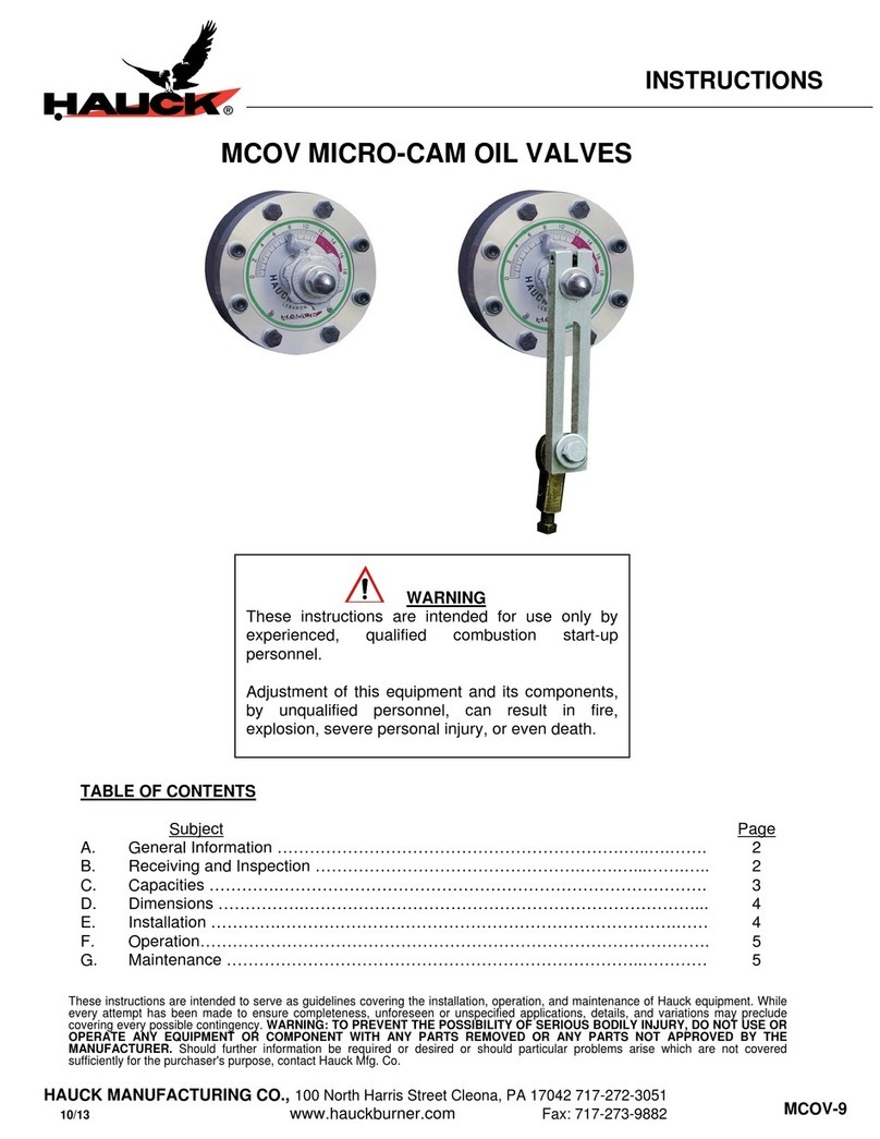
MCOV MICRO-CAM OIL VALVES
TABLE OF CONTENTS
Subject Page
A. General Information ……………………………………………………….…..….……. 2
B. Receiving and Inspection ………………………………………….…….…...…….….. 2
C. Capacities ………….……………………………………………………………………. 3
D. Dimensions …………….………………………………………………………………... 5
E. Installation ………….……………………………………………………………….…… 7
F. Operation…………………………………………………………………………………. 7
G. Maintenance …………………………………………………………………..………… 7
INSTRUCTIONS
MCOV-9
WARNING
These instructions are intended for use only by
experienced, qualified combustion start-up
personnel.
Adjustment of this equipment and its components,
by unqualified personnel, can result in fire,
explosion, severe personal injury, or even death.
These instructions are intended to serve as guidelines covering the installation, operation, and maintenance of Hauck equipment. While
every attempt has been made to ensure completeness, unforeseen or unspecified applications, details, and variations may preclude
covering every possible contingency. WARNING: TO PREVENT THE POSSIBILITY OF SERIOUS BODILY INJURY, DO NOT USE OR
OPERATE ANY EQUIPMENT OR COMPONENT WITH ANY PARTS REMOVED OR ANY PARTS NOT APPROVED BY THE
MANUFACTURER. Should further information be required or desired or should particular problems arise which are not covered
sufficiently for the purchaser's purpose, contact Hauck Mfg. Co.
HAUCK MANUFACTURING CO., P.O. Box 90 Lebanon, PA 17042-0090 717-272-3051
11/12 www.hauckburner.com Fax: 717-273-9882

Page 2
MCOV-9
A. GENERAL INFORMATION
The Hauck Micro-Cam Oil Valve is designed to provide positive, accurate, graduated control of
fuel oil flow to any type of burner. Flow control may be either manual or automatic. A large
indicator dial provides a greater range of individual precision settings. This valve is specifically
engineered to handle large oil capacities while providing a graduated flow through its range.
The Hauck Micro-Cam Oil Valve is intended for flow control; it is not designed to replace a
shutoff valve. For tight shutoff, a ball type or solenoid shutoff valve must be provided in the fuel
supply line. These valves will successfully and efficiently handle any grade of fuel oil, even
heavy fuel oils, when preheated to the proper viscosity and flow characteristics.
B. RECEIVING AND INSPECTION
Upon receipt, check each item on the bill of lading and/or invoice to determine that all
equipment has been received. A careful examination of all parts should be made to ascertain if
there has been any damage in shipment.
WARNING
This equipment is potentially dangerous with the possibility of serious personal injury
and property damage. Hauck Manufacturing Company recommends the use of flame
supervisory equipment and fuel safety shutoff valves. Furthermore, Hauck urges rigid
adherence to National Fire Protection Association (NFPA) standards and insurance
underwriter’s requirements. Operation and regular preventative maintenance of this
equipment should be performed only by properly trained and qualified personnel.
Annual review and upgrading of safety equipment is recommended.
IMPORTANT
If the installation is delayed and the equipment is
stored outside, provide adequate protection as
dictated by climate and period of exposure. Special
care should be given to all motors and bearings, if
applicable, to protect them from rain or excessive
moisture.

Page 3
MCOV-9
C. CAPACITIES
PIPE PRESSURE DROP (psig)
MODEL SIZE 1 5 10 15 20 25 30 35 40 45 50 75 100
NUMBER NPT OIL CAPACITY (gph) @ 180° VALVE POSITION
B-1/2-12 1/2 20 44 63 77 89 100 110 118 126 134 141 173 200
B-1/2-16 1/2 30 70 98 116 134 150 164 177 189 201 212 260 300
B-1/2-18 1/2 38 89 120 147 170 190 207 224 239 255 268 329 380
B-1/2-20 1/2 50 116 156 192 222 248 271 292 312 332 349 428 495
B-1/2-24 1/2 67 157 211 260 300 335 366 395 422 449 472 580 670
Table 1. B Series Valves
PIPE PRESSURE DROP (psig)
MODEL SIZE 1 5 10 15 20 25 30 35 40 45 50 75 100
NUMBER NPT OIL CAPACITY (gph) @ 120° VALVE POSITION
F-1/2-16 1/2 28 62 88 108 124 140 154 165 176 187 197 242 280
F-1/2-18 1/2 49 109 155 189 218 245 269 289 308 328 345 423 490
F-1/2-20 1/2 75 167 237 290 333 375 412 442 472 502 528 648 750
F-1/2-24 1/2 117 261 369 453 520 585 643 690 737 783 824 1012 1170
G-1-29 1 153 342 484 594 682 767 843 905 966 1027 1081 1326 1534
K-1-29 1 182 406 575 705 809 910 1001 1073 1146 1219 1283 1574 1820
K-1-38 1 245 547 774 949 1090 1225 1347 1445 1543 1641 1727 2119 2450
Table 2. F,G & K Series Valves
PIPE PRESSURE DROP (psig)
MODEL SIZE 1 5 10 15 20 25 30 35 40 45 50 75 100
NUMBER NPT OIL CAPACITY (gph) @ FULL OPEN VALVE POSITION
BL-1/2-16 1/2 6.5 33 66 99 132 165 198 231 264 297 330 495 660
FL-1/2-20 1/2 16 81 162 243 324 405 486 567 648 729 810 1215 1620
FL-1/2-24 1/2 24 120 240 360 480 600 720 840 960 1080 1200 1800 2400
GL-1-29 1 29 144 288 432 576 720 864 1008 1152 1296 1440 2160 2880
Table 3. L-Cam Series Valves
PIPE PRESSURE DROP (psig)
MODEL SIZE 1 5 10 15 20 25 30 35 40 45 50 75 100
NUMBER NPT LP CAPACITY (gph) @ 120° VALVE POSITION
H-1/2-16 1/2 38 85 120 147 170 190 208 225 240 255 269 329 380
H-1/2-20 1/2 99 221 313 383 443 495 542 586 626 664 700 857 990
H-1/2-24 1/2 155 347 490 600 693 775 849 917 980 1040 1096 1342 1550
J-1-29 1 200 447 632 775 894 1000 1095 1183 1265 1342 1414 1732 2000
K-1-29 1 230 514 727 891 1029 1150 1260 1361 1455 1543 1626 1992 2300
K-1-38 1 324 724 1025 1255 1449 1620 1775 1917 2049 2173 2291 2806 3240
Table 4. LP Series Valves
NOTES:
1. Capacities based on No. 2 fuel oil at .849 s.g. and 60°F or liquid propane at 0.057 s.g. and 60°F.
2. Pressure drop across full open valve. Actual test data measured at 25 psig pressure drop, all other capacities
calculated.
3. When ordering, specify if valve is to be equipped with hand lever, hand wheel or adjustable radius lever for
automatic control.

Page 4
MCOV-9
C. CAPACITIES (Metric Capacities)
PIPE PRESSURE DROP (kPa)
MODEL SIZE 6.9 35 69 103 138 172 207 241 276 310 345 517 690
NUMBER NPT OIL CAPACITY (lph) @ 180° VALVE POSITION
B-1/2-12 1/2 76 167 238 291 337 379 416 447 477 507 534 655 757
B-1/2-16 1/2 114 265 371 439 507 568 621 670 715 761 802 984 1136
B-1/2-18 1/2 144 337 454 556 643 719 783 848 905 965 1014 1245 1438
B-1/2-20 1/2 189 439 590 727 840 939 1026 1105 1181 1257 1321 1620 1874
B-1/2-24 1/2 254 594 799 984 1136 1268 1385 1495 1597 1699 1787 2195 2536
Table 5. Metric B Series Valves
PIPE PRESSURE DROP (kPa)
MODEL SIZE 6.9 35 69 103 138 172 207 241 276 310 345 517 690
NUMBER NPT OIL CAPACITY (lph) @ 120° VALVE POSITION
F-1/2-16 1/2 106 235 333 409 469 530 583 625 666 708 746 916 1060
F-1/2-18 1/2 185 413 587 715 825 927 1018 1094 1166 1241 1306 1601 1855
F-1/2-20 1/2 284 632 897 1098 1260 1419 1559 1673 1787 1900 1998 2453 2839
F-1/2-24 1/2 443 988 1397 1715 1968 2214 2434 2612 2790 2964 3119 3830 4428
G-1-29 1 579 1294 1832 2248 2581 2903 3191 3425 3656 3887 4092 5019 5806
K-1-29 1 689 1537 2176 2668 3062 3444 3789 4061 4338 4614 4856 5958 6889
K-1-38 1 927 2070 2930 3592 4126 4637 5098 5469 5840 6211 6537 8020 9273
Table 6. Metric F,G & K Series Valves
PIPE PRESSURE DROP (kPa)
MODEL SIZE 6.9 35 69 103 138 172 207 241 276 310 345 517 690
NUMBER NPT OIL CAPACITY (lph) @ FULL OPEN VALVE POSITION
BL-1/2-16 1/2 25 125 250 375 500 625 749 874 999 1124 1249 1874 2498
FL-1/2-20 1/2 61 307 613 920 1226 1533 1840 2146 2453 2759 3066 4599 6132
FL-1/2-24 1/2 91 454 908 1363 1817 2271 2725 3179 3634 4088 4542 6813 9084
GL-1-29 1 110 545 1090 1635 2180 2725 3270 3815 4360 4905 5450 8176 10900
Table 7. Metric L-Cam Series Valves
PIPE PRESSURE DROP (kPa)
MODEL SIZE 6.9 35 69 103 138 172 207 241 276 310 345 517 690
NUMBER NPT LP CAPACITY (lph) @ 120° VALVE POSITION
H-1/2-16 1/2 144 322 455 557 643 719 788 851 910 965 1017 1246 1438
H-1/2-20 1/2 375 838 1185 1451 1676 1874 2052 2217 2370 2514 2650 3245 3747
H-1/2-24 1/2 587 1312 1855 2272 2624 2933 3213 3471 3710 3936 4148 5081 5867
J-1-29 1 757 1693 2394 2932 3385 3785 4146 4478 4788 5078 5353 6556 7570
K-1-29 1 871 1947 2753 3372 3893 4353 4768 5150 5506 5840 6156 7539 8706
K-1-38 1 1226 2742 3878 4750 5484 6132 6717 7255 7756 8227 8672 10620 12263
Table 8. LP Series Valves
NOTES:
1. Capacities based on No. 2 fuel oil at .849 s.g. and 15.5°C or liquid propane at 0.507 s.g. and 15.5°C.
2. Pressure drop across full open valve. Actual test data measured at 172 kPa pressure drop, all other capacities
calculated.
3. When ordering, specify if valve is to be equipped with hand lever, hand wheel or adjustable radius lever for
automatic control.

Page 5
MCOV-9
D. DIMENSIONS
Figure 1. Dimensions
Y1388
(NOT TO SCALE)

Page 6
MCOV-9
D. DIMENSIONS (Continued)
Figure 2. Metric Dimensions
Y1388 METRIC
(
NOT TO SCALE
)

Page 7
MCOV-9
E. INSTALLATION
1. Using a high quality thread sealant (Loctite 565 or equal) on the fittings, install the oil control
valve in the oil line in any position, at a convenient location as close to the burner as possible.
To prevent air pocket formation in the burner oil supply line, mount the MCOV at or below the
burner centerline. The valve should be placed downstream of a shutoff valve and a filter. The
shutoff valve makes it possible to clean the filter and service the burner and control valve
without shutting down the oil supply system. The filter will help prevent clogging by removing
any debris which is too large to pass through the control valve. All micro-cam oil valves are
provided with female connections threaded for standard pipe.
2. When an automatic operation is to be used, mount a control motor to some nearby rigid
support. The valve’s operating arm moves in a clockwise direction to open the valve over an
arc of 180° (B series) or 120° (F, G and K series) at an adjustable radius ranging from 1-1/8"
to 4-3/8" (29 to 111mm).
A. Connect the valve lever to the control motor arm by a 3/8" (9.5mm) rod through the snap
connection pin on the valve lever. A set screw is provided on the snap pin to secure the
rod at the proper point.
B. Adjust the length of the control motor arm so that the valve pointer moves through the
desired range on the valve dial. Since the maximum travel of most control motors is only
90°, the full capacity of the valve cannot be obtained. Be sure that the control motor does
not move the valve lever beyond the stops on the dial as this can damage the valve if
sufficient force is applied.
3. All heavy fuel oil piping must be heat (electric or steam) traced and insulated. Self-regulating
heat tracing is recommended to maintain the desired temperature of a given fuel to achieve 90
SSU (1.8x10⁵m2/s) at the burner. Electrical heat tracing with a nominal rating of 12 W/ft (39
W/m) covered with a nominal 2" (50 mm) of fiberglass type insulation is sufficient for most
applications. Heating the oil lines without fuel flow is not recommended.
When operating the valve with heavy oil, it is recommended that the fuel piping is purged when
not in use to protect the components in the fuel train. Failure to purge the fuel lines may result in
deposits forming in the valve or line, or coking of the heavy fuel oils which may affect the valve
or system performance.
F. OPERATION
All Hauck Micro-Cam Oil Valves are designed to efficiently handle any grade of fuel oil, even the
heaviest residues. The heavy grades must be preheated to achieve the proper viscosity for
atomization, normally 90 SSU (1.84 x 10⁻⁵ m2/sec).
The large, easily readable indicator dial enables the valve to be set, or reset, to any setting
required by the application.
G. MAINTENANCE
All Hauck Micro-Cam Oil Valves are designed for maintenance free operation. Under normal
usage, no service should be necessary.
NOTE
Due to the critical nature of the alignment of the
valve’s internal components, and it’s operating
pressures, Hauck does not recommend
disassembly of Micro-Cam Oil Valves. Such
disassembly will void warranty.

Page 8
MCOV-9
This page left intentionally blank.
HAUCK MANUFACTURING CO., P.O. Box 90 Lebanon, PA 17042-0090 717-272-3051
www.hauckburner.com Fax: 717-273-9882
This manual suits for next models
20
Table of contents
Other Hauck Control Unit manuals
Popular Control Unit manuals by other brands

Automationdirect.com
Automationdirect.com HX-ECOM Series manual

Behringer
Behringer 130 DUAL VCA quick start guide

Server
Server 82433 quick start guide

Bosch
Bosch KTS 5 Series Original instructions

Continental Refrigerator
Continental Refrigerator FE4NA0210 Manual and user guide

GE
GE TLE Scalable 150 quick start guide