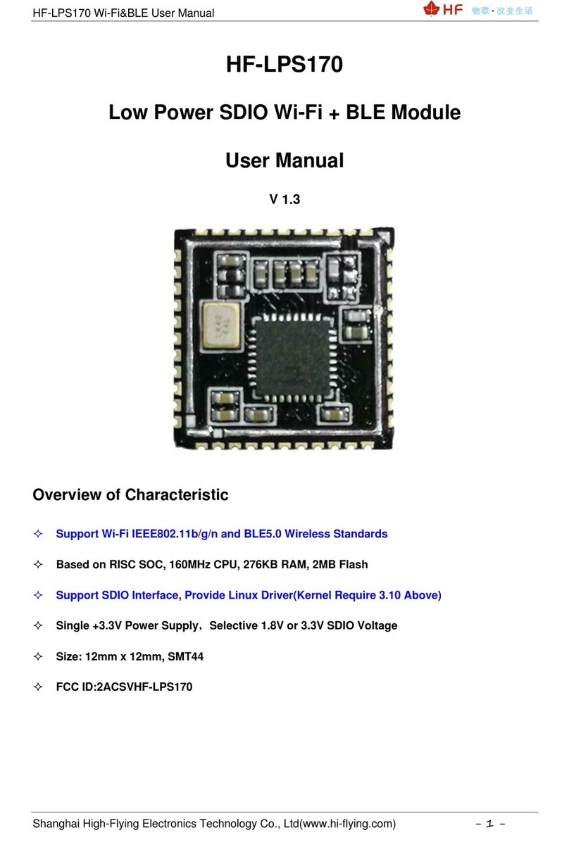
HF Elfin-EG1 Series User manual

Elfin-EG1X 用户手册
http://www.iotworkshop.com - 1 -
Elfin-EG1X
RS232/RS485 to GPRS
User Manual
V 1.2
Overview of Characteristic
Support Four Frequency Bands, Global Standard (850/900/1800/1900M Hz)
Support GSM/GPRS and CMCC or CUCC SIM Card
Support RS232/RS485 to GPRS Data Transmission, Serial Port Speed Up to 460800bps
Supports Max 3 Channel TCP/UDP connections, Each Connection Supports 1400 Bytes of Data
Cache, and the Network Channel Can be Bound to the Serial Port.
Support Multiple Working Modes: Network Transparent Transmission Mode, HTTP Mode
Support IOTService Tool, Remotely and Dynamically Modify Module Parameters
Support SMS AT Command Configuration
Supports Registration Packet , Heartbeat Packet Function, and the Registration Package Supports
ICCID, IMEI, IMSI, Software Version number, GPRS Connection Status and other Combinations.
Support NTP
Support Modbus TCP to Modbus RTU

Elfin-EG1X 用户手册
http://www.iotworkshop.com - 2 -
Support IOTBridge for Remote Control and Config.
Support IOTBridge working time, for example only works from 10:00 to 10:30 to save the data flow
charge.
Support Serial Port, Network OTA Upgrade Firmware.
Size: 61 x 26 x 17.8mm
9~18VDC Wide Power Supply

Elfin-EG1X 用户手册
http://www.iotworkshop.com - 3 -
TABLE OF CONTENTS
TABLE OF CONTENTS....................................................................................................................3
LIST OF FIGURES............................................................................................................................4
LIST OF TABLES .............................................................................................................................4
1. PRODUCT OVERVIER ........................................................................................................5
1.1. General Description.........................................................................................................5
1.2. Device Parameters...........................................................................................................5
1.3. Key Applications..............................................................................................................6
2. HARDWARE INTRODUCTION ...........................................................................................8
2.1. APPEARANCE..................................................................................................................8
2.2. Elfin-EG10 Pin Definition.................................................................................................9
2.3. Elfin-EG11 Pin Definition...............................................................................................10
2.4. RS232 Interface..............................................................................................................10
2.5. RS485 Interface..............................................................................................................11
2.6. Mechanical Size .............................................................................................................11
2.7. RJ45 8PIN Connector ....................................................................................................11
2.8. RJ45 4PIN Connector ....................................................................................................12
2.9. EG10 Interface Conversion Cable................................................................................14
2.10. EG11 Interface Conversion Cable................................................................................15
2.11. Fixed Bracket .................................................................................................................15
2.12. Rail Bracket ....................................................................................................................16
2.13. Bracket............................................................................................................................16
2.14. RJ45 Transform Connector...........................................................................................18
2.15. Product Installation .......................................................................................................18
2.16. EVK..................................................................................................................................19
2.17. Product Order Information............................................................................................19
APPENDIX A: CONTACT INFORMATION....................................................................................21

Elfin-EG1X 用户手册
http://www.iotworkshop.com - 4 -
LIST OF FIGURES
Figure 1. Elfin-EG11 Appearance...................................................................................................................8
Figure 2. Elfin-EG10 Appearance...................................................................................................................8
Figure 3. Elfin-EG10 RJ45 Interface Pin.........................................................................................................9
Figure 4. Elfin-EG11 RJ45 Interface Pin.......................................................................................................10
Figure 5. Elfin-EG1X Mechanical Size..........................................................................................................11
Figure 6. RJ45 8PIN Connector....................................................................................................................12
Figure 7. EG10+8PIN Connector..................................................................................................................12
Figure 8. EG11+8PIN Connector..................................................................................................................12
Figure 9. RJ45 4PIN Connector....................................................................................................................13
Figure 10. EG10 +4PIN Connector.................................................................................................................13
Figure 11. EG11+4PIN Connector..................................................................................................................13
Figure 12. Interface Conversion Cable ...........................................................................................................14
Figure 13. Cable Manufacture Guide..............................................................................................................15
Figure 14. Interface Conversion Cable ...........................................................................................................15
Figure 15. Fixed Bracket.................................................................................................................................15
Figure 16. Rail Bracket ...................................................................................................................................16
Figure 17. Bracket Size...................................................................................................................................16
Figure 18. Bracket Install Picture....................................................................................................................17
Figure 19. RJ45 Transform Connector............................................................................................................18
Figure 20. Product Installation........................................................................................................................18
Figure 21. EVK Package.................................................................................................................................19
Figure 22. Elfin-EG1X Product Order Information...........................................................................................20
LIST OF TABLES
Elfin-EG1X Technical Specifications ......................................................................................................5
Elfin-EG10 Interface Definition ...............................................................................................................9
Elfin-EG11 Interface Definition .............................................................................................................10
HISTORY
V 1.0 06-25-2018. First Version
Ed. V1.1 09-18-2018 Modify power input range. Fix LED description. Add more attachedment
description.
Ed. V1.2 04-19-2019 Update accessories.

Elfin-EG1X 用户手册
http://www.iotworkshop.com - 5 -
1.PRODUCT OVERVIER
1.1. General Description
The Elfin-EG1X can meet almost all M2M needs, including automotive and personal tracking
services, wireless POS machines, smart metering, industrial PDAs, shared bikes, shared cars and
more.
The Elfin-EG1X module is an Ethernet RJ45 interface serial server with ultra-small size: 61 x 26
x 17.8mm
Elfin-EG1X Internal Frame Diagram
1.2. Device Parameters
Elfin-EG1X Technical Specifications
Item
Parameter
Wireless Parameter
GPRS Band
GSM850, EGSM900, DCS1800, PCS1900
GPRS Transmit
Power
GSM850/EGSM900: 5dbm~32.5dbm
DCS1800/PCS1900: 0dbm~29.5dbm
GPRS Receiving
Sensitivity
<-108.5dBm
GPRS Connection
Features
GPRS Multi-Slot Level is 10 (default)
GPRS Mobile Station Level B

Elfin-EG1X 用户手册
http://www.iotworkshop.com - 6 -
GPRS Date Features
GPRS Data Downlink Transmission: Up to 85.6 kbps
GPRS Data Uplink Transmission: Up to 85.6 kbps
Encoding Format: CS-1, CS-2, CS-3 and CS-4
GPRS Antenna
Interface
Characteristic
Impedance
50Ω
Serial Port
Port Number
1
Interface Standard
RS232/RS485
Data Bits
7, 8
Stop Bits
1, 2
Check Bit
None,Even,Odd
Baud Rate
TTL:1200 bps~460800 bps,
Flow Control
No Flow Control
Half Flow Control(RS485)
Software
Configuration
Serial AT Command
IOTService Serial Port Configuration Software
IOTService Network Configuration Software
Firmware Upgrade
Serial Port or OTA Upgrade
Basic Parameter
SIM Card Interface
Support Nano-SIM Card: 1.8V, 3V
Working Temp
-40°C~85°C
Storage Temp
-45°C~90°C
Input Voltage
9V~18VDC
Start 20s Average
Current
61mA
Networked Standby
Average Current
22mA
100 bytes/10
Seconds to Send
Data Average
Current
57mA
100 bytes/5
Seconds to Send
Data Average
Current
91mA
100 bytes/2
Seconds to Send
Data Average
Current
233mA
Peak Current
2A
Size
61 x 26 x 17.8mm
1.3. Key Applications
The Elfin-EG1X module connects the serial device to the Internet and conforms to the TCP/IP
protocol for transmitting serial data.
⚫Remote device monitoring

Elfin-EG1X 用户手册
http://www.iotworkshop.com - 7 -
⚫Production asset tracking and monitoring
⚫Security field
⚫Industrial sensors and controllers
⚫Health medical equipment
⚫ATM equipment
⚫Data acquisition equipment
⚫UPS power management equipment
⚫Telecommunication equipment
⚫Data display device
⚫Hand-held device
⚫Attendance system and terminal equipment

Elfin-EG1X 用户手册
http://www.iotworkshop.com - 8 -
2.HARDWARE INTRODUCTION
Elfin-EG1X is a GPRS solution for serial device networking. Data transmission via GPRS makes
product integration very easy. This product meets EMC Class B security level and can pass relevant
certification tests in various countries.
2.1. APPEARANCE
Figure 1. Elfin-EG11 Appearance
Figure 2. Elfin-EG10 Appearance

Elfin-EG1X 用户手册
http://www.iotworkshop.com - 9 -
2.2. Elfin-EG10 Pin Definition
Figure 3. Elfin-EG10 RJ45 Interface Pin
Elfin-EG10 Interface Definition
Pin
Description
Net Name
Signal Type
Notes
1
GPIO
GPIO
IO
Reserved
2
GPIO
GPIO
IO
Reserved
3
GPIO
GPIO
IO
Reserved
4
Restore to
Factory
nReload
I
Default high. Long press this button
("Low">3s) and loose to make the module
restore to factory setting.
5
UART_1TX
UART1_TXD
O
RS232
6
UART_1RX
UART1_RXD
I
RS232
7
Power VCC
VCC
Power
9~18VDC
8
Power GND
GND
Power
9
Green LED
Net Status
Net
O
Boot On: Power is OK.
2s Off -> 2s On: GPRS Register is OK.
0.1s Off -> 0.1s On: GPRS data is
transferring.
10
Amber LED
Data Transfer
Active
O
Off: No data transfer
0.3s Off -> 0.9s On: UART TX Output
0.3s Off -> 0.3s On: UART RX Receive
On: UART bidirection.

Elfin-EG1X 用户手册
http://www.iotworkshop.com - 10 -
2.3. Elfin-EG11 Pin Definition
Figure 4. Elfin-EG11 RJ45 Interface Pin
Elfin-EG11 Interface Definition
Pin
Description
Net Name
Signal Type
Notes
1
Debug TX
HOST_TXD
O
TTL Voltage
2
Debug RX
HOST_RXD
I
TTL Voltage
3
GPIO
GPIO
IO
Reserved
4
Restore to
Factory
nReload
I
Default high. Long press this button
("Low">3s) and loose to make the module
restore to factory setting.
5
UART1_TXD
RS485_A+
IO
RS485 A+
6
UART1_RXD
RS485_B-
IO
RS485 B-
7
Power VCC
VCC
Power
9~18VDC
8
Power GND
GND
Power
9
Green LED
Net Status
Net
O
Boot On: Power is OK.
2s Off -> 2s On: GPRS Register is OK.
0.1s Off -> 0.1s On: GPRS data is
transferring.
10
Amber LED
Data Transfer
Active
O
Off: No data transfer
0.3s Off -> 0.9s On: UART TX Output
0.3s Off -> 0.3s On: UART RX Receive
On: UART bidirection.
<Notes>:
I —Input; O —Output; Power—Power Supply
2.4. RS232 Interface
RS232 don’t have hardware flow control function, and the physical voltage is ±8V.

Elfin-EG1X 用户手册
http://www.iotworkshop.com - 11 -
2.5. RS485 Interface
RS485 use two wire links, A(DATA+), B(DATA-). Connect A(+) to A(+), B(-) to B(-) for communication.
Suggest to connect GND together when interference is very severe.
The RS485 interface support maximum 32 485 device, device. The cable maximum length is 1200
meters. Need to add 120Ohm terminal resistor for over 300 meters.
2.6. Mechanical Size
The dimensions of Elfin-EG1X are defined as following pictures(mm):
Figure 5. Elfin-EG1X Mechanical Size
2.7. RJ45 8PIN Connector
RJ45 8PIN Connector Type Order: 10810001001
This manual suits for next models
2
Table of contents
Other HF Control Unit manuals
Popular Control Unit manuals by other brands

auto maskin
auto maskin Marine Pro 200 Series user manual
MAYSER
MAYSER SG-RSV 205 operating instructions
ATI Technologies
ATI Technologies QC-11HM manual
Apator
Apator AT-WMBUS-04 Operation and Maintenance Documentation
Advantech
Advantech AMAX-175 Series user manual

Aqualisa
Aqualisa Quartz Thermo QZ3111 manual


