Haufftechnik PolySafe User manual
ma_polysafe_dicht_manschette_200319
Hauff-Technik GmbH & Co. KG
Robert-Bosch-Straße 9
89568 Hermaringen, GERMANY
Tel. +49 7322 1333-0
Fax +49 7322 1333-999
ofce@hauff-technik.de
www.hauff-technik.de
Art. Nr.: 5090033070 Rev.:05/2020-03-19
Vor Beginn der Montage Anleitung lesen und gut aufbewahren!
Read the instructions prior to installation and keep them in a safe place!
Lire les instructions avant le montage et bien les conserver!
www.hauff-technik.de
Immer. Sicher. Dicht.Immer. Sicher. Dicht.
2
Art. Nr.: 5090033070 Rev.:05/2020-03-19
PolySafe - Spartendichtelemente und Manschetten-
stopfen
6
1 2
5
3
78
4
Montageanleitung PolySafe -
Spartendichtelemente und Manschettenstopfen. DE
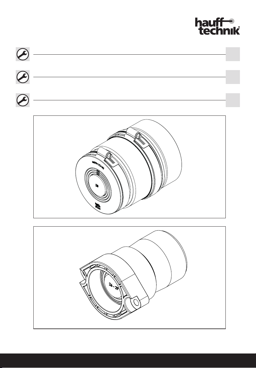
Abb.: Manschettenstopfen MS78U 1x24-52
Installation instructions PolySafe -
Utility sealing elements and sleeve caps. EN
Abb.: Spartendichtelement SDE 1x20-34
Instructions d‘ installation PolySafe -
Éléments d’étanchéité de lignes et bouchons de manchettes. FR
1
2
4
3
1
2
3
4
1
2
3
4
1
2

ma_polysafe_dicht_manschette_200319
Hauff-Technik GmbH & Co. KG
Robert-Bosch-Straße 9
89568 Hermaringen, GERMANY
Tel. +49 7322 1333-0
Fax +49 7322 1333-999
ofce@hauff-technik.de
www.hauff-technik.de
Art. Nr.: 5090033070 Rev.:05/2020-03-19
Vor Beginn der Montage Anleitung lesen und gut aufbewahren!
Read the instructions prior to installation and keep them in a safe place!
Lire les instructions avant le montage et bien les conserver!
www.hauff-technik.de
Immer. Sicher. Dicht.Immer. Sicher. Dicht.
2
Art. Nr.: 5090033070 Rev.:05/2020-03-19
PolySafe - Spartendichtelemente und Manschetten-
stopfen
6
1 2
5
3
78
4
Montageanleitung PolySafe -
Spartendichtelemente und Manschettenstopfen. DE
Abb.: Manschettenstopfen MS78U 1x24-52
Installation instructions PolySafe -
Utility sealing elements and sleeve caps. EN
Abb.: Spartendichtelement SDE 1x20-34
Instructions d‘ installation PolySafe -
Éléments d’étanchéité de lignes et bouchons de manchettes. FR
1
2
4
3
1
2
3
4
1
2
3
4
1
2
Art. Nr.: 5090033070 Rev.:05/2020-03-19Art. Nr.: 5090033070 Rev.:05/2020-03-19 Art. Nr.: 5090033070 Rev.:05/2020-03-19 2543
PolySafe - Spartendichtelemente und Manschetten-
stopfen
PolySafe - Spartendichtelemente und Manschetten-
stopfen EN
Notizen / Notes / Remarques
10
11
9
12
13 14
15 16
1
2
3
4
18
19
17
20
21 22
23 24
1
2
3
4
1
2
3
4
1
2
3
4
1
2
3
4
1
2
3
4
5
Art. Nr.: 5090033070 Rev.:05/2020-03-19
PolySafe - Spartendichtelemente und Manschetten-
stopfen
26
27
25
28
29 30
31
1
1
2
2
2
1
44
4
3
5

6Art. Nr.: 5090033070 Rev.:05/2020-03-19
PolySafe - Spartendichtelemente und Manschetten-
stopfen
Sicherheitshinweise und Informationen
Zielgruppe
Die Montage darf nur von sachkundigen Personen durchgeführt werden.
Qualizierte und geschulte Personen für die Montage haben
• die Kenntnis der allgemeinen Sicherheits- und Unfallverhütungsvorschriften in
der jeweils gültigen Fassung,
• die Kenntnis in der Anwendung von Sicherheitsausrüstung,
• die Kenntnis im Umgang mit Hand- und Elektrowerkzeugen,
• die Kenntnis der einschlägigen Normen und Richtlinen zum Verlegen von Rohren/
Kabeln und zum Verfüllen von Leitungsgräben in der jeweils gültigen Fassung,
• die Kenntnis der Vorschriften und Verlegerichtlinien des Versorgungsunternehmens
in der jeweils gültigen Fassung,
• die Kenntnis der WU-Beton Richtlinie und der Bauwerksabdichtungsnormen in
der jeweils gültigen Fassung.
Allgemeines und Verwendungszweck
Unsere Produkte sind entsprechend ihrer bestimmungsgemäßen Verwendung
ausschließlich für den Einbau in Bauwerke entwickelt, deren Baustoffe dem derzei-
tigen Stand der Technik entsprechen. Für eine andere oder darüber hinaus gehende
Verwendung, sofern sie nach Rücksprache mit uns nicht ausdrücklich schriftlich
bestätigt wurde, übernehmen wir keine Haftung.
Die Gewährleistungsbedingungen entnehmen Sie unseren aktuellen AGB (Allgemeine
Verkaufs- und Lieferbedingungen).
Die Manschettenstopfen sind zum sicheren Abdichten des Mantelrohrs zum
Elektrokabel, zur Wasserleitung, zu Telekommunikationsleitungen und zu Fernwär-
meleitungen geeignet.
Die Universal-Dichtelemente sind für jede Sparte - Strom, Wasser und Telekom-
munikation geeignet.
Sicherheit
Dieser Abschnitt gibt einen Überblick über alle wichtigen Sicherheitsaspekte für
einen optimalen Schutz des Personals sowie für einen sicheren Montageablauf. Bei
Nichtbeachtung der in dieser Anweisung aufgeführten Handlungsanweisungen und
Sicherheitshinweise können erhebliche Gefahren entstehen.
Bei der Montage der Manschettenstopfen und Universal-Dichtelemente müssen die
entsprechenden Vorschriften der Berufsgenossenschaften, die VDE-Bestimmungen, die
entsprechenden nationalen Sicherheits- und Unfallverhütungsvorschriften sowie die
Richtlinien (Arbeits- und Verfahrensanweisungen) Ihres Unternehmens beachtet werden.
Der Monteur muss die entsprechende Schutzausrüstung tragen.
Es dürfen nur unbeschädigte Teile montiert werden.
Vor der Montage der Dichtelemente und Manschettenstopfen
sind folgende Hinweise zu beachten:
WARNUNG!
Verletzungsgefahr durch unsachgemäße Montage!
Unsachgemäße Montage kann zu erheblichen Personen und Sachschäden führen.
• Grundsätzlich sind die national gültigen Verlege- und Verfüllvorschriften für Rohre
und Kabel zu beachten.
• Untergrund und Rohrunterbau vor der Rohr-/Kabelverlegung gut verdichten, damit
kein Absinken der Rohre/Kabel möglich ist.
HINWEIS!
Keine Abdichtung durch unsachgemäße Montage!
Unsachgemäße Montage kann zu Sachschäden führen.
• Spartendichtelemente sind keine Festpunkte oder Lager und können somit keine
mechanischen Kräfte aufnehmen.
• Die Kabel müssen gerade im Spartendichtelement sitzen und dürfen durch einen
eventuell anschließenden Biegeradius nicht mechanisch belastet werden.
• Nicht benötigte Öffnungen müssen mit Verschlussstopfen verschlossen bleiben,
bzw. mit dem Blind-Dichtelement SD0 verschlossen werden.
• Kabel dürfen im Dichtbereich keine durchgängigen Längsriefen aufweisen.
• Kabel müssen schmutzfrei und sauber sein.
• Bei dünnwandigen oder geschäumten Rohren dürfen die Spannbänder der Manschet-
tenstopfen nur so stark angezogen werden, dass sich die Rohre nicht deformieren.
• Die hier aufgeführten Normen und Richtlinien sind ausschließlich in Deutschland
gültig. Bei allen anderen Ländern sind die nationalen Normen und Richtlinien in
gültiger Fassung anzuwenden.
• Für die Reinigung der PolySafe Dichtelemente und Manschettenstopfen dürfen
keine lösungsmittelhaltigen Reiniger verwendet werden. Wir empfehlen den
Kabelreiniger KRMTX.
• Weiteres Zubehör und Informationen unter www.hauff-technik.de und in den
technischen Datenblättern.
Personalanforderungen
Qualikationen
WARNUNG!
Verletzungsgefahr bei unzureichender Qualikation!
Unsachgemäßer Umgang kann zu erheblichen Personen und Sachschäden führen.
• Montage darf nur von qualizierten und geschulten Personen durchgeführt
DE werden, welche diese Montageanweisung gelesen und verstanden haben.
Fachpersonal
Fachpersonal ist aufgrund seiner fachlichen Ausbildung, Kenntnisse und Erfahrung
sowie Kenntnis der einschlägigen Bestimmungen, Normen und Vorschriften in der
Lage, die ihm übertragenen Arbeiten auszuführen und mögliche Gefahren selbstständig
zu erkennen und zu vermeiden.
Transport, Verpackung, Lieferumfang und Lagerung
Sicherheitshinweise zum Transport
HINWEIS!
Beschädigungen durch unsachgemäßen Transport!
Bei unsachgemäßem Transport können Sachschäden in erheblicher Höhe entstehen.
• Beim Abladen der Packstücke bei Anlieferung sowie innerbetrieblichem Transport
vorsichtig vorgehen und die Symbole auf der Verpackung beachten.
Transportinspektion
Die Lieferung bei Erhalt unverzüglich auf Vollständigkeit und Transportschäden prüfen.
Bei äußerlich erkennbarem Transportschaden wie folgt vorgehen:
• Lieferung nicht oder nur unter Vorbehalt entgegennehmen.
• Schadensumfang auf den Transportunterlagen oder auf dem Lieferschein des
Transporteurs vermerken.
• Jeden Mangel reklamieren, sobald er erkannt ist.
•Schadenersatzansprüche können nur innerhalb der geltenden Reklamations-
fristen geltend gemacht werden.
Lieferumfang
Zum Lieferumfang der Universal-Manschettenstopfen für glatte und gewellte
Rohre DA75-90
MS78U 1x24-52 - Universal-Manschettenstopfen Wasser/Elektro
MS78EW 1x24-40+3x7-14+2x5-8 - Manschettenstopfen für Elektro/Wasser
MS78K 1x13-21+3x7-13+1x5-13 - Manschettenstopfen für Kommunikation
MS78 D0 - Manschettenstopfen zur Blindabdichtung
MS78 zxd - Manschettenstopfen mit individueller Belegung
gehören:
1 Manschettenstopfen inkl. Blindstopfen
1 bzw. 2 Edelstahl-Spannbänder
Zum Lieferumfang der Universal-Dichtelemente
Wasser SDW 1x32/40/50
Elektro SDE 1x20-34
Elektro SDE 1x26-29/36-39/43-46/48-51
Elektro/Kommunikation SDEK 1x26-30+3x5-8+2x7-13
Kommunikation SDK 1x13-21+3x7-13+1x5-13
Elektro/Kommunikation SDEK 1x25-36+3x7-14+2x5-10
Zweigeteilte Dichtelemente mit Edelstahlplatte, z.B. Wasser/Elektro
SDEW 1x32-34/40/43+2x7/10-13
Blind SD0 (Dichtelement zur Blindabdichtung)
SDX zxd (Dichtelement mit individueller Belegung)
gehören:
1 Dichtelement inkl. Blindstopfen
1 Lasche
Die passenden Schrauben für die PolySafe Dichtelemente sind bei sämtlichen
Ein- und Mehrsparten-Hauseinführungen beigelegt.
Lagerung
HINWEIS!
Beschädigungen durch unsachgemäße Lagerung!
Bei unsachgemäßer Lagerung können Sachschäden in erheblicher Höhe entstehen.
• Die Manschettenstopfen und Universal-Dichtelemente vor der Montage vor
Beschädigungen, Feuchte und Verunreinigungen schützen. Es dürfen nur
unbeschädigte Teile montiert werden.
• Die Lagerung der Manschettenstopfen und Universal-Dichtelemente muss
so erfolgen, dass sie zu keinen niederen Temperaturen (<5° C) und höheren
Temperaturen (>30° C) sowie keiner direkten Sonneneinstrahlung ausgesetzt ist.
Entsorgung
Sofern keine Rücknahme- oder Entsorgungsvereinbarung getroffen wurde, zerlegte
Bestandteile nach sachgerechter Demontage der Wiederverwertung zuführen:
• Metallische Materialreste nach den geltenden Umweltvorschriften verschrotten
• Elastomere nach den geltenden Umweltvorschriften entsorgen.
• Kunststoffe nach den geltenden Umweltvorschriften entsorgen.
• Verpackungsmaterial nach den geltenden Umweltvorschriften entsorgen.

67
Art. Nr.: 5090033070 Rev.:05/2020-03-19
PolySafe - Spartendichtelemente und Manschetten-
stopfen
Transport, packaging, scope of delivery and storage
Safety instructions in connection with transport
NOTE!
Damage in the event of improper transport!
Signicant damage can occur in the event of improper transport.
• When unloading packaging items on delivery and in the course of in-house transport,
proceed with care and observe the symbols on the packaging.
Transport inspection
Inspect the delivery immediately on receipt for completeness and transport damage.
In the event of transport damage being visible from the outside, proceed as follows:
• Do not accept the delivery or only do so subject to reservations.
• Make a note of the extent of damage in the transport documentation or delivery
note provided by the transporter.
• Submit a claim for every defect as soon as it has been identified.
•Make a note of the extent of damage in the transport documentation or
delivery note provided by the transporter.
Scope of delivery
The universal sleeve caps for smooth and corrugated pipes DA75-90,
MS78U 1x24-52 – Universal sleeve cap, water/electricity
MS78EW 1x24-40+3x7-14+2x5-8 – Sleeve cap for electricity/water
MS78K 1x13-21+3x7-13+1x5-13 – Sleeve cap for communication
MS78 D0 – Sleeve cap for blind sealing
MS78 zxd – Sleeve cap with individual assignment
are supplied with the following:
1 sleeve cap incl. blind plug
2 stainless steel tension straps
The universal sealing elements,
Water SDW 1x32/40/50
Electricity SDE 1x20-34
Electricity SDE 1x26-29/36-39/43-46/48-51
Electricity/communication SDEK 1x26-30+3x5-8+2x7-13
Communication SDK 1x13-21+3x7-13+1x5-13
Electricity/communication SDEK 1x25-36+3x7-14+2x5-10
Two-part sealing elements with stainless steel plate, e.g. water/electrical
SDEW 1x32-34/40/43+2x7/10-13
Blind SD0 (sealing element for blind sealing)
SDX zxd (sealing element with individual assignment)
are supplied with the following:
1 sealing element incl. blind plug
1 tab
The matching screws for the PolySafe sealing elements are included with all
single and multi-utility building entries.
Storage
NOTICE!
Damage due to improper storage!
Signicant damage can occur in the event of improper storage.
• Protect the universal sealing elements and sleeve caps from damage, damp and
soiling prior to installation. Only intact components may be installed.
• The universal sealing elements and sleeve caps must be stored in such a way
that it is not exposed to low temperatures (<5° C), high temperatures (>30°
C) or direct sunlight.
Disposal
If no return or disposal agreement has been concluded, recycle dismantled components
after they have been properly dismantled:
• Metal remains are to be scrapped according to existing environmental regulations.
• Dispose of elastomer segments according to existing environmental regulations.
• Dispose of plastics according to existing environmental regulations.
• Dispose of packaging material according to existing environmental regulations.
Instructions de sécurité et informations
Public
Ce montage peut être effectué uniquement par des personnes compétentes.
Les personnes qualiées et formées pour le montage
• ont connaissance des règles de sécurité et de prévention actuellement en vigueur,
• savent utiliser un équipement de sécurité,
• savent manier des outils manuels et électriques,
• ont connaissance des normes et directives actuellement en vigueur pour la pose
de tuyaux/câbles et pour le remplissage de tranchées,
• ont connaissance de la règlementation et des consignes actuellement en vigueur
FR
Safety instructions and informations
Target group
The installation may only be carried out by technical experts.
Qualied and trained individuals carrying out installation must have
• knowledge of general safety and accident prevention regulations as amended,
• knowledge of how to use safety equipment,
• knowledge of how to use hand tools and electric tools,
• knowledge of the relevant standards and guidelines for laying pipes/cables and
for backlling utility trenches, as amended,
• knowledge of the regulations and installation guidelines of the supply company
as amended,
• knowledge of the impermeable concrete directive and building waterproong
standards as amended.
General information and intended use
According to their intended use, our products have been designed exclusively for
installation in buildings made from state-of-the-art construction materials. We do
not accept liability for use deviating from or beyond this unless our express written
conrmation has been obtained in advance.
For warranty conditions, please see our current General Terms and Delivery Conditions.
The sleeve caps are designed to ensure reliable sealing of the sleeve pipe to electric
cables, water pipes, telecommunication lines and district heating cables.
The universal sealing elements are suitable for all utility types – electricity, water
and telecommunications.
Safety
This section provides an overview of all the main safety aspects for optimum protec-
tion of personnel and a safe installation process. If there is a failure to observe the
instructions and safety information set out here, this may result in signicant hazards.
The sealing elements or sleeve caps installation must comply with the relevant profes-
sional association regulations, VDE provisions, national safety and accident prevention
regulations as well as company regulations (work and procedural instructions).
The tter must wear the relevant protective clothing.
Only intact components may be installed.
The following instructions are to be observed prior to installa-
tion of PolySafe sealing elements and sleeve caps:
WARNING!
Risk of injury in the event of improper installation!
Improper installation can result in signicant bodily harm and property damage.
• The nationally applicable laying and lling regulations for pipes and cables are
to be observed at all times.
• Seal the underground and cable substructure well prior to laying pipes/cables so
that the latter cannot subside.
NOTICE!
No sealing due to incorrect assembly!
Improper installation can result in damage.
• Utility sealing elements are not xed settlement points or bearings and therefore
cannot absorb any mechanical forces.
• The cable must be mounted straight in the universal sealing element and must not
be subjected to mechanical stress from any subsequent bend radius.
• Openings that are not required must remain sealed with blind plugs or with the
SD0 sealing element plug.
• There must not be any continuous longitudinal score marks on the cables in
the seal area.
• Cables must be clean and free from dirt.
• In the case of thin-walled or foamed pipes, only tighten the tension straps of the
sleeve caps up to a point at which the pipes are not deformed.
• The norms and directives referred to here are valid in Germany only. In all other
countries, the national norms and directives are to be observed as amended.
• No cleaning agents containing solvent may be used to clean the cable seal. We
recommend using cable cleaner KRMTX.
• For details of other accessories and further information, see www.hauff-technik.
de and the technical specication sheets.
Personnel requirements
Qualications
WARNING!
Risk of injury in case of inadequate qualication!
Improper handling can result in signicant bodily harm and damage to property.
• Installation may only be carried out by qualied and trained individuals who have
read and understood these instructions.
Skilled experts
Based on their specialist training, skills, experience and familiarity with the relevant
provisions, standards and regulations, skilled experts are able to carry out the worked
assigned, independently identifying and avoiding potential hazards.
EN

8Art. Nr.: 5090033070 Rev.:05/2020-03-19
PolySafe - Spartendichtelemente und Manschetten-
stopfen
des entreprises de fourniture en énergie,
• ont connaissance des prescriptions d'utilisation du béton étanche de WU et des
normes relatives à l'étanchéité d'ouvrages actuellement en vigueur.
Informations générales et utilisation prévue
Conformément à l‘usage prévu, nos produits sont conçus exclusivement pour être
intégrés dans des constructions dont les matériaux sont conformes à la réglementa-
tion technique en vigueur. Nous déclinons toutes responsabilités dans le cas d‘une
utilisation non-conforme pour l’usage indiqué si nous n‘avons pas donné notre
accord par écrit après consultation.
Les termes de la garantie sont précisés dans nos Conditions de vente et livraison actuelles.
Les bouchons de manchettes sont appropriés pour l’étanchement sûr du tube de
gainage par rapport au câble électrique, à la conduite d’eau, aux lignes de télécom-
munication et aux conduites de chauffage urbain.
Les éléments d’étanchéité universels conviennent pour chaque ligne d’électricité,
d’eau et de télécommunication.
Sécurité
Cette section donne un aperçu de tous les aspects essentiels en terme de sécurité
an de protéger au maximum le personnel et de garantir un montage sécurisé. En
cas de non-respect des instructions de manipulation et des consignes de sécurité
mentionnées dans les présentes instructions, l'utilisateur s'expose à de graves dangers.
Lors du montage des éléments d’étanchéité et/ou des bouchons de manchettes,il
convient de respecter les réglementations correspondantes des associations professi-
onnelles, les directives de la fédération allemande des industries de l'électrotechnique,
de l'électronique et de l'ingénierie de l'information (VDE), les règles nationales en
vigueur relatives à la sécurité et à la prévention des accidents, ainsi que les directives
(consignes de travail et procédures) de votre entreprise.
Le monteur doit porter l'équipement de protection adéquat.
Ne monter que des piéces non endommagées.
Les instructions suivantes sont à prendre en compte avant le
montage du Éléments d’étanchéité de lignes et bouchons de
manchettes:
AVERTISSEMENT !
Un montage non conforme peut entraîner un risque de blessure !
Un montage non conforme peut entraîner des dommages corporels et matériels
considérables.
• Les recommandations de pose et de remplissage des tuyaux et câbles doivent être
systématiquement respectées.
• Bien étanchéiser le sous-sol et l'infrastructure des tuyaux avant la pose des tuyaux/
câbles an d'empêcher les tuyaux/câbles de couler.
REMARQUE !
Un montage non conforme ne garantit aucune étanchéité !
Un montage non conforme peut entraîner des dommages matériels.
• Les éléments d‘étanchéité universels ne sont pas des points xes ou des paliers
et, par conséquent, ne sont pas en mesure d‘absorber les efforts mécaniques.
• Les câbles doivent être positionnés directement dans l‘élément d‘étanchéité
universel et ne doivent pas être endommagés mécaniquement par un rayon de
courbure qui en résulterait.
• Les orices non utilisés doivent rester obturés avec des obturateurs adaptés ou
l‘élément d‘étanchéité borgne SD0.
• Les câbles ne doivent présenter aucune strie longitudinale continue dans la
zone d‘étanchéité.
• Les câbles doivent être propres et exempts de saleté.
• En cas d’utilisation de tubes à paroi mince ou en matériau expansé, il convient de
serrer les colliers de serrage des bouchons de manchettes avec une intensité qui
ne provoque en aucun cas une déformation des tuyaux.
• Les normes et directives citées ici ne sont valables qu'en Allemagne. Pour tous
les autres pays, les normes et directives nationales dans leur version en vigueur
doivent être appliquées.
• Aucun produit à base de solvant ne doit être utilisé pour le nettoyage de la join
annulaire standard. Nous recommandons le produit nettoyant pour câble KRMTX.
• D‘autres accessoires et informations sont disponibles sous www.hauff-technik.
de et dans les ches techniques.
Personnel requis
Qualications
AVERTISSEMENT !
Risque de blessure en cas de qualication insufsante !
Une utilisation inappropriée peut entraîner des dommages corporels et matériels
considérables.
• Le montage peut uniquement être effectué par des personnes qualiées et formées
ayant lu et compris ces instructions de montage.
Personnel spécialisé
En raison de sa formation spécialisée, de ses connaissances et de son expérience ainsi
que de sa connaissance des dispositions, normes et recommandations, le personnel
spécialisé est en mesure d'effectuer les tâches qui lui sont transmises ainsi que de
reconnaître et d'éviter seul les dangers potentiels.
Transport, emballage, contenu de la livraison et stockage
Instructions de sécurité pour le transport
REMARQUE !
Dommages suite à un transport inapproprié !
Un transport inapproprié peut entraîner des dommages considérables.
• Lors du déchargement des colis à la livraison et pendant le transport au sein
de l'entreprise, veuillez procéder avec précaution et respecter les symboles sur
l'emballage.
Inspection après transport
À la réception de la livraison, veuillez vérier immédiatement si elle est compléte
ainsi que d'éventuels dommages dus au transport.
Si des dommages devaient être constatés suite au transport, veuillez procéder
comme suit :
• Ne pas accepter la livraison ou alors l'accepter sous réserve.
• Indiquer l'étendue des dommages dans les documents de transport ou dans le
bon de livraison du transporteur.
• Faire une réclamation au moindre défaut dès qu'il est constaté.
•Les demandes de dédommagement peuvent être uniquement soumises dans
les délais de réclamation applicables.
Contenu de la livraison
Le contenu de la livraison des bouchons de manchettes universels pour tuyaux
lisses et annelés DA75-90
MS78U 1x24-52 - Bouchon de manchette universel pour eau potable
et électricité
MS78EW 1x24-40+3x7-14+2x5-8 - Bouchon de manchette universel pour
eau potable et électricité
MS78K 1x13-21+3x7-13+1x5-13 - Bouchon de manchette pour lignes de
communication
MS78 D0 - Bouchon de manchette pour étanchement borgne
MS78 zxd - Bouchon de manchette pour occupation individuelle
comprend :
1 bouchon de manchette avec bouchon borgne
2 colliers de serrage en acier inoxydable
Le contenu de la livraison des éléments d’étanchéité universels
Eau SDW 1x32/40/50
Électricité SDE 1x20-34
Électricité SDE 1x26-29/36-39/43-46/48-51
Électricité/communications SDEK 1x26-30+3x5-8+2x7-13
Communications SDK 1x13-21+3x7-13+1x5-13
Électricité/communications SDEK 1x25-36+3x7-14+2x5-10
Éléments d'étanchéité en deux parties avec plaque en acier inoxydable,
p. ex. eau/électricité
1x32-34/40/43+2x7/10-13
SD0 (élément d’étanchéité borgne pour étanchement borgne)
SDX zxd (élément d’étanchéité pour occupation individuelle)
comprend :
1 élément d’étanchéité avec bouchon borgne
1 bride
Les vis adaptées pour les éléments d’étanchéité PolySafe sont jointes à toutes
les entrées de bâtiment monolignes et multilignes.
Stockage
REMARQUE !
Dommages suite à un stockage non conforme !
Un stockage non conforme peut entraîner des dommages considérables.
• Protégez les bouchons de manchettes et les éléments d’étanchéité universels
lors de l’installation contre les endommagements, l’humidité et les impuretés !
• Le stockage les bouchons de manchettes et les éléments d’étanchéité universels doit
être réalisé de maniére à ce qu‘elles ne soient pas exposées à des basses tempéra-
tures (<5 °C) et des températures élevées (>30 °C) ni aux rayons directs du soleil.
Élimination des déchets
Si aucun contrat de reprise ou d'élimination n'a été conclu, aprés un démontage
adéquat les composants désassemblés doivent être envoyés au recyclage :
• Les restes métalliques doivent être mis au rebut dans le respect des normes
environnementales en vigueur.
• Les déchets élastoméres doivent être éliminés dans le respect des normes envi-
ronnementales en vigueur.
• Les déchets plastiques doivent être éliminés dans le respect des normes environ-
nementales en vigueur.
• Le matériel d'emballage doit être éliminé dans le respect des normes environ-
nementales en vigueur.

89
Art. Nr.: 5090033070 Rev.:05/2020-03-19
Inhaltsverzeichnis
1 Impressum
Copyright © 2019 by
Hauff-Technik GmbH & Co. KG
Abteilung: Technische Redaktion
Robert-Bosch-Straße 9
89568 Hermaringen, GERMANY
Tel. +49 7322 1333-0
Fax +49 7322 1333-999
E-Mail ofce@hauff-technik.de
Internet www.hauff-technik.de
Die Vervielfältigung der Montageanleitung - auch aus-
zugsweise - als Nachdruck, Fotokopie, auf elektronischem
Datenträger oder irgendein anderes Verfahren bedarf
unserer schriftlichen Genehmigung.
Alle Rechte vorbehalten.
Technische Änderungen jederzeit und ohne jede Voran-
kündigung vorbehalten.
Diese Montageanweisung ist Bestandteil des Produkts.
Gedruckt in der Bundesrepublik Deutschland
2 Symbolerklärung
1Arbeitsschritte
Bezugsnummerierung in Zeichnungen
1
►Folge/Resultat eines Arbeitsschrittes
3 Benötigtes Werkzeug und Hilfsmittel
Für die ordnungsgemäße Installation der Manschettenstop-
fen und Universal-Dichtelemente benötigen Sie neben dem
üblichen Standardwerkzeug die folgenden Werkzeuge und
Hilfsmittel:
Einzeldichtelemente
Steckschlüsseleinsatz für Innensechskantschraube SW6
Manschettenstopfen
Steckschlüssel SW7
4 Beschreibung und Montage Man-
schettenstopfen für glatte und
gewellte Rohre DA75-90
Legende zu Abb.: 1
1Manschettenstopfen
2Spannschelle
3Segmentring
4Blindstopfen
1 Impressum...........................................................9
2 Symbolerklärung ................................................9
3 Benötigtes Werkzeug und Hilfsmittel...............9
4 Beschreibung und Montage Manschettenstop-
fen für glatte und gewellte Rohre DA75-90.....9
4.1 * MS78U 1x24-52 -
Universal-Manschettenstopfen für Elektro/
Wasser...............................................................9
4.2 MS78EW 1x24-40+3x7-14+2x5-8
Universal-Manschettenstopfen für Elektro/
Wasser/Kommunikation......................................10
4.3 * MS78K 1x13-21+3x7-13+1x5-13 - Manschetten-
stopfen für Kommunikation ............................... 10
4.4 * MS78 D0 -
Manschettenstopfen zur Blindabdichtung ..10
4.5 MS78 zxd -
Manschettenstopfen mit individueller
Belegung ...........................................................10
5 Montage an Rohrenden ...................................10
6 Beschreibung und Montage
Dichtelemente...................................................11
6.1 * SDW 1x32/40/50 -
Universal-Dichtelement für Wasser..............11
6.2 * SDE 1x20-34 -
Universal-Dichtelement für Elektro..............11
6.3 SDE 1x26-29/36-39/43-46/48-51 -
Universal-Dichtelement für Elektro.................11
6.4 SDEK 1x26-30+3x5-8+2x7-13 -
Universal-Dichtelement für
Elektro und Kommunikation............................12
6.5 * SDK 1x13-21+3x7-13+1x5-13 -
Universal-Dichtelement für Kommunikation .12
6.6 SDEK 1x25-36+3x7-14+2x5-10 -
Universal-Dichtelement für Elektro und
Kommunikation .....................................................12
6.7 SDEW 1x32-34/40/43+2x7/10-13 Universal-
Dichtelement für Wasser und Elektro .................12
6.8 SD0 -
Blind-Dichtelement zum Verschluss nicht
belegter Sparten...............................................12
6.9 Individuelles-Dichtelement mit individueller
Belegung ...........................................................13
7 Dichtelemente montieren ................................13
PolySafe - Spartendichtelemente und Manschetten-
stopfen DE
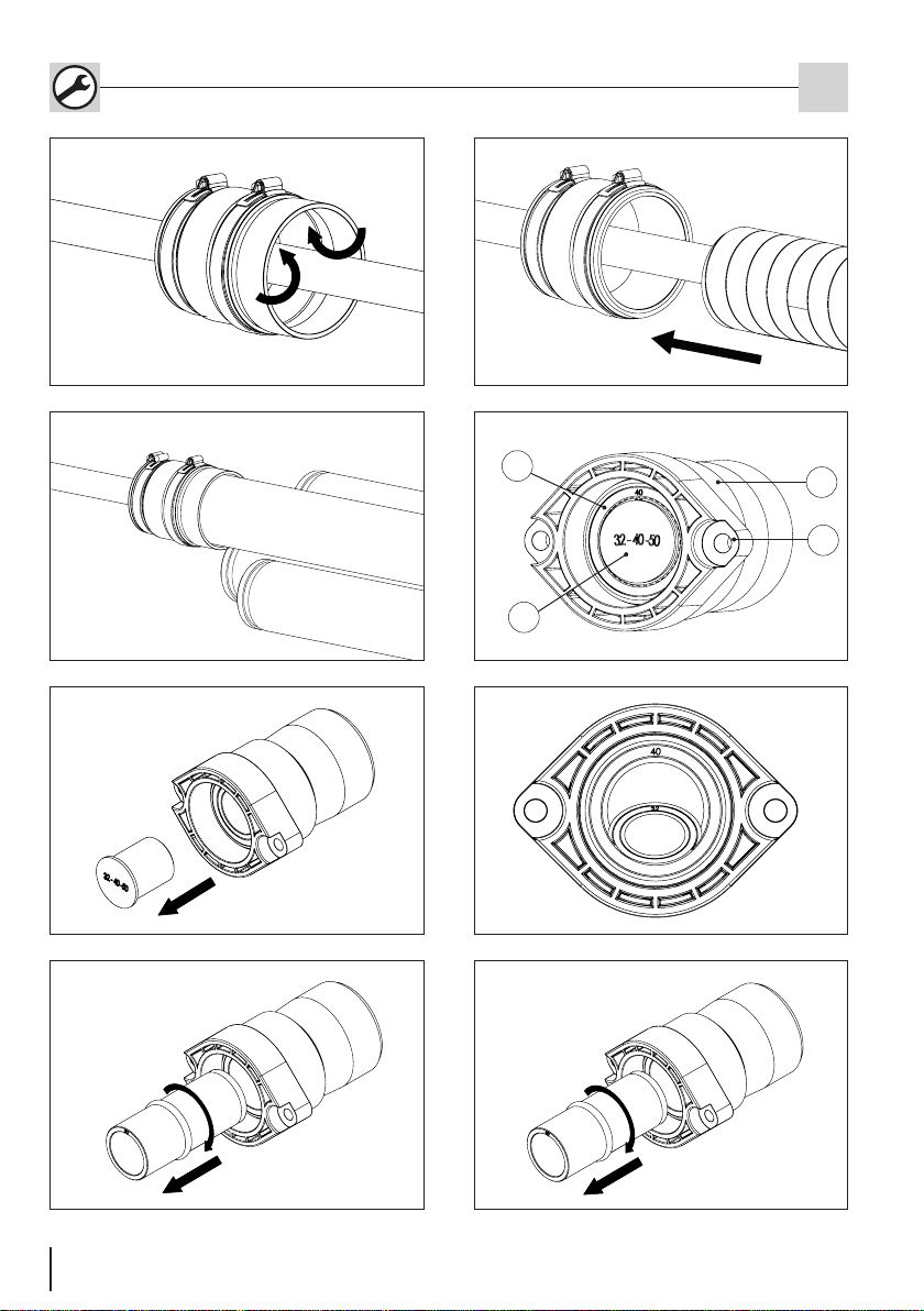
4.1 * MS78U 1x24-52 -
Universal-Manschettenstopfen für
Elektro/Wasser
Anwendungsbereich:
1x Ø 24 - 52 mm
1Für den Kabel-/Rohrdurchmesser 24-28 mm wird der
Blindstopfen nach vorne aus dem Manschettenstopfen
entfernt (siehe Abb.: 2).
Für alle weiteren Anwendungsbereiche werden mit
einem Längsschlitzschraubendreher, je nach Kabel-/
Rohrdurchmesser, die Segmentschnitte vom Universal-
Manschettenstopfen durchstoßen und entfernt (siehe
Tabelle 1).
10 Art. Nr.: 5090033070 Rev.:05/2020-03-19
4.2 MS78EW 1x24-40+3x7-14+2x5-8
Universal-Manschettenstopfen für
Elektro/Wasser/Kommunikation
Legende zu Abb.: 3
1Manschettenstopfen
2Spannschelle
3Segmentring
4Blindstopfen
Anwendungsbereich:
1x Ø 24 - 40 mm
3x Ø 7 - 14 mm
2x Ø 5 - 8 mm
1Beim Universal-Manschettenstopfen - Elektro/Wasser
und Kommunikation (Durchmesser 5 bis 40 mm),
werden je nach Bedarf, die entsprechenden Blind-
stopfen und Segmentringe (siehe Tabelle 1) entfernt
(siehe Abb.: 4).
4.3 * MS78K 1x13-21+3x7-13+1x5-13 -
Manschettenstopfen für Kommu-
nikation
Legende zu Abb.: 5
1Manschettenstopfen
2Spannschelle
3Segmentring
4Blindstopfen
Anwendungsbereich:
1x Ø 13 - 21 mm
3x Ø 7 - 13 mm
1x Ø 5 - 13 mm
1Beim Manschettenstopfen - Kommunikation (Durch-
messer 5 bis 21 mm), werden je nach Bedarf, die
entsprechenden Blindstopfen und Segmentringe (siehe
Tabelle 1) entfernt (siehe Abb.: 6).
4.4 * MS78 D0 -
Manschettenstopfen zur Blindab-
dichtung
Legende zu Abb.: 7
1Manschettenstopfen
2Spannschelle
Anwendungsbereich:
Blindabdichtung
1Die Montage für den Blind-Manschettenstopfen er-
folgt sinngemäß wie in den Arbeitsschritten 1-3 im
Abschnitt 5 beschrieben.
4.5 MS78 zxd -
Manschettenstopfen mit individuel-
ler Belegung
Anwendungsbereich:
z x Ø
1Die Montage für den Manschettenstopfen mit
individueller Belegung erfolgt sinngemäß wie in
den Abschnitten 4.1-4.4 beschrieben. Individuelle
Manschettenstopfen haben keine Segmentringe, son-
dern nur Blindstopfen.
5 Montage an Rohrenden
1Nachdem die Hausanschlussleitungen über die
Leerrohrtrasse eingeschoben wurden, werden die
Manschettenstopfen über zwei Spannbänder am
Hateexschlauchende 14078 bzw. an glatten und
gewellten Rohrenden ab DA 80-90 mm xiert und
zur Medienleitung hin abgedichtet (Anzugsmoment
3 Nm) (siehe Abb.: 8).
2Bei glatten und gewellten Rohren DA 75 bzw. beim
ESH-Mantelrohr muss das zweite Spannband gelöst
und die äußere Gummilippe des Manschettenstopfens
nach innen umgestülpt werden (siehe Abb.: 9).
Das Mantelrohr in die Manschette einschieben und mit
dem Spannband xieren (siehe Abb.: 10).
3Bei Mantelrohren der MSH-Wanddurchführungen
werden die Manschettenstopfen über die zwei Spann-
bänder xiert (siehe Abb.: 11).
Die Gummilippe der Manschettenstopfen bleibt in
diesem Anwendungsfall ausgeklappt.
Der Blind-Manschettenstopfen wird mit nur einer
Spannschelle xiert.
Bei dünnwandigen oder geschäumten Rohren
dürfen die Spannbänder der Manschettenstopfen
nur so stark angezogen werden, dass sich die Rohre
nicht deformieren!
PolySafe - Spartendichtelemente und Manschetten-
stopfen DE
Standardmanschettenstopfen sind mit einem
* gekennzeichnet.
Diese sind als Set für jede Mehrsparten-
hauseinführung erhältlich.
MSH Zubehör Set 1 (Art. Nr.: 1552002101) (Set
mit Gasabschlussstopfen)
MSH Zubehör Set 3 (Art. Nr.: 1552002120) (Set
mit Blindabdichtung)

10 11
Art. Nr.: 5090033070 Rev.:05/2020-03-19
PolySafe - Spartendichtelemente und Manschetten-
stopfen DE
6.2 * SDE 1x20-34 -
Universal-Dichtelement für Elektro
Legende zu Abb.: 17
1Universal-Dichtelement
2Befestigungslasche
3Segmentring
4Blindstopfen
Anwendungsbereich:
Ø 20-25 mm
Ø 26-34 mm
1Blindstopfen und ggf. Segmentring entfernen.
Siehe hierzu die Arbeitsschritte 1 bis 4 im Abschnitt
6.1 (siehe Abb.: 18)
Legende zu Abb.: 12
1Universal-Dichtelement
2Befestigungslasche
3Segmentring
4Blindstopfen
6.3 SDE 1x26-29/36-39/43-46/48-51 -
Universal-Dichtelement für Elektro
Anwendungsbereich:
Ø 26-29 mm
Ø 36-39 mm
Ø 43-46 mm
Ø 48-51 mm
Legende zu Abb.: 19
1Universal-Dichtelement
2Befestigungslasche
3Segmentring
4Blindstopfen
1Blindstopfen und ggf. Segmentring entfernen.
Siehe hierzu die Arbeitsschritte 1 bis 4 im Abschnitt
6.1 (siehe Abb.: 20 )
6 Beschreibung und Montage
Dichtelemente
6.1 * SDW 1x32/40/50 -
Universal-Dichtelement für Wasser
Anwendungsbereich:
Ø 32 mm
Ø 40 mm
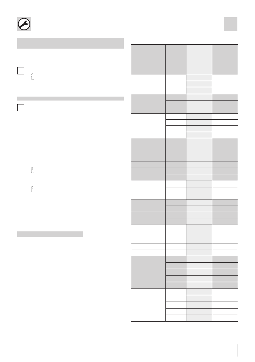
Ø 50 mm
Anwendungs-
bereich
Manschetten-
stopfen
Seg-
ment-
ring
Istmaße
Segment-
schnitte
(mm)
(siehe auch
Beschriftung auf
den Manschet-
tenstopfen)
Rohr/Kabel-
durchmesser
d (mm)
Universal
1x24-52
Stopfen 28 24-28
Nr. 1 29-35 29-34
Nr. 2 35-41 35-40
Nr. 3 41-47 41-46
Nr.4 47-52 47-52
Wasser
1x24-40
Stopfen 28 24-28
Nr. 1 29-35 29-34
Nr. 2 36-40 35-40
3x7-14 Stopfen 7-9 7-9
Nr. 1 10-14 10-14
2x5-8 Stopfen 5-8 5-8
Kommuni-
kation
1x13-21
Stopfen 13-18 13-18
Nr. 1 18-21 19-21
3x7-13 Stopfen 7-9 7-9
Nr. 1 9-13 10-13
1x5-13 Stopfen 5-8 5-7
Nr. 1 8-13 8-13
Individuell
zxd
- - Ø da (+1/-2)
Tabelle 1
1Anwendungsbereich: 32 mm
Für den Anwendungsbereich 32 mm wird der Blind-
stopfen aus dem Universaldichtelement entfernt (siehe
Abb.: 13).
2Anwendungsbereich: 40 mm
Blindstopfen w.o. beschrieben entfernen.
Anschließend wird der erste Segmentring auf beiden
Seiten, an der Vorder- und Rückseite zusammen ge-
drückt bis eine durchgehende Falte entsteht (siehe
Abb.: 14 und Tab. 2).
3
Anwendungsbereich: 50 mm
Zum Entfernen des zweiten Segmentringes (Durch-
messer 50 mm) ist so vorzugehen wie in den Ar-
beitsschritten 1 bis 3 beschrieben (siehe Abb.: 16
und Tab. 2).
4
Der Segmentring wird an dieser Falte kräftig drehend
herausgezogen (kann wahlweise auch mit einem
Schraubendreher erfolgen) (siehe Abb.: 15)..

12 Art. Nr.: 5090033070 Rev.:05/2020-03-19
PolySafe - Spartendichtelemente und Manschetten-
stopfen DE
6.4 SDEK 1x26-30+3x5-8+2x7-13 -
Universal-Dichtelement für Elektro
und Kommunikation
Anwendungsbereich:
1x Ø 26-30 mm
3x Ø 5-8 mm
2x Ø 7-13 mm
Legende zu Abb.: 21
1Universal-Dichtelement
2Befestigungslasche
3Blindstopfen
4Blindstopfen mit Hülse
1Blindstopfen und ggf. Segmentringe entfernen.
Beim Elektro-/Telekommunikations-Dichtelement wer-
den, je nach Bedarf, die entsprechenden Blindstopfen
und Segmentringe entfernt (siehe Abb.: 22).
Siehe hierzu die Arbeitsschritte 1 bis 4 im Ab-
schnitt 6.1.
6.5 * SDK 1x13-21+3x7-13+1x5-13 -
Universal-Dichtelement für Kom-
munikation
Anwendungsbereich:
1x Ø 13-21 mm
3x Ø 7-13 mm
1x Ø 5-13 mm
Legende zu Abb.: 23
1Universal-Dichtelement
2Befestigungslasche
3Segmentring
4Blindstopfen
1Blindstopfen und ggf. Segmentringe entfernen.
Beim Kommunikations-Dichtelement werden, je nach
Bedarf, die entsprechenden Blindstopfen und Seg-
mentringe entfernt (siehe Abb.: 24).
Siehe hierzu die Arbeitsschritte 1 bis 4 im Ab-
schnitt 6.1.
6.6 SDEK 1x25-36+3x7-14+2x5-10 -
Universal-Dichtelement für Elektro
und Kommunikation
Anwendungsbereich:
1x Ø 25-36 mm
3x Ø 7-14 mm
2x Ø 5-10 mm
Legende zu Abb.: 25
1Universal-Dichtelement
2Befestigungslasche
3Segmentring
4Blindstopfen
1Für den Anwendungsbereich Ø 25-36 mm werden mit
einem Längsschlitzschraubendreher die Membrane
durchstoßen und entfernt (siehe Abb.: 26).
Für die kleineren Anwendungsbereiche Ø 5-10 mm und
Ø 7-14 mm wird mit einem Längsschlitzschraubendre-
her nur die Membrane durchstoßen (siehe Tabelle 2).
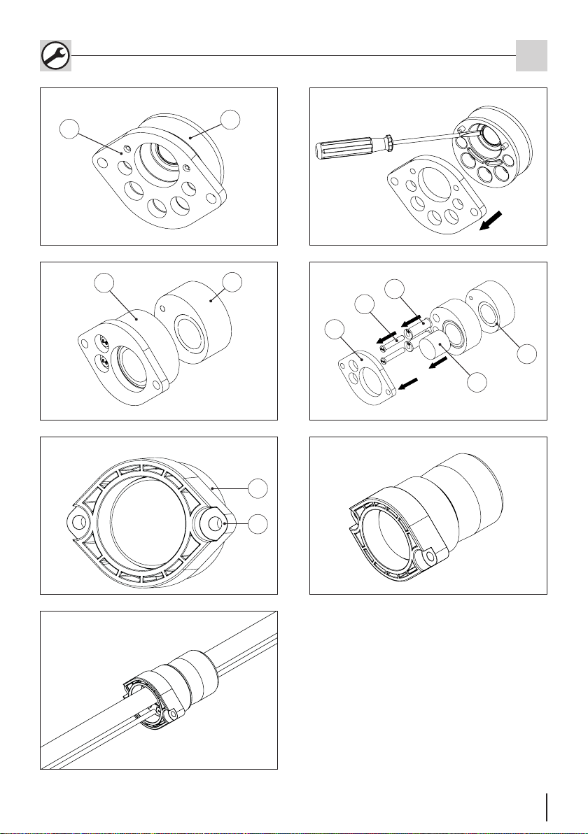
6.7 SDEW 1x32-34/40/43+2x7/10-13
Universal-Dichtelement für Wasser
und Elektro
Anwendungsbereich:
1x Ø 32-34 mm, 40 mm, 43 mm
2x Ø 7 mm, 10-13 mm
Legende zu Abb.: 27
1Universal-Dichtelement
2Sekundär-Dichtelement
3Befestigungslasche
4Blindstopfen
5Segmentring
1Beim Wasser-/Elektro-Dichtelement werden, je nach
Bedarf, die entsprechenden Blindstopfen und Seg-
mentringe entfernt (siehe Abb.: 28).
Für das Sekundär-Dichtelement wird mit einem Messer
oder einem Längsschlitzschraubendreher die Perfo-
rierung entsprechend dem benötigten Durchmesser
durchtrennt.
6.8 SD0 -
Blind-Dichtelement zum Verschluss
nicht belegter Sparten
Anwendungsbereich:
Blindabdichtung
Legende zu Abb.: 29
1Universal-Dichtelement
2Befestigungslasche
Die Montage für das Blind-Dichtelement SD0
erfolgt sinngemäß wie in 7 „Dichtelemente mon-
tieren“, beschrieben (siehe Abb.: 29).
Nicht belegte Öffnungen des Dichtelementes
müssen verschlossen bleiben.
12 13
Art. Nr.: 5090033070 Rev.:05/2020-03-19
PolySafe - Spartendichtelemente und Manschetten-
stopfen DE
Service-Telefon +49 7322 1333-0
Änderungen vorbehalten.
6.9 Individuelles-Dichtelement mit indi-
vidueller Belegung
Anwendungsbereich:
Je nach individueller Ausführung.
1Blindstopfen und ggf. Segmentring entfernen.
Die Montage für das Individuelle-Dichtelement
erfolgt sinngemäß wie in Abschnitt 7 „Dichtele-
mente montieren”, beschrieben (siehe Abb.: 30).
7 Dichtelemente montieren
1
Standarddichtelemente sind mit einem *
gekennzeichnet.
Diese sind als Set für jede Mehrsparten-
hauseinführung erhältlich.
MSH PolySafe Dichtelemente-Set (Art. Nr.:
1560000500)
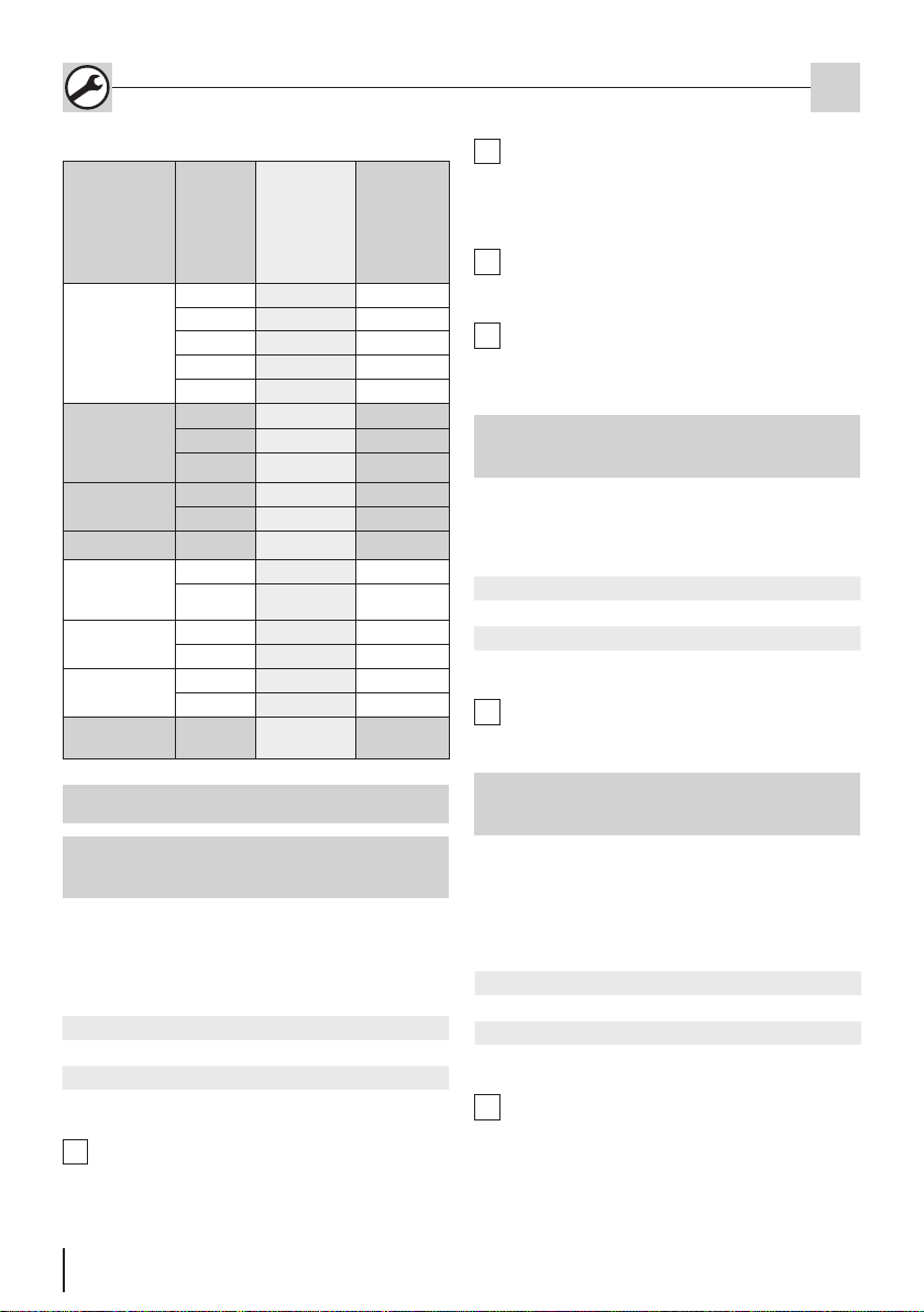
Anwendungs-
bereich
Segment-
ring
Istmaße
Segment-
schnitte
(mm)
(siehe Beschrif-
tung auf den
Dichtelementen)
Rohr/Kabel-
durchmesser
d (mm)
Universal -
Dichtelement für
Wasser
SDW 1x32/40/50
Stopfen 32 32
Nr. 1 40 40
Nr. 2 50 50
Universal-
Dichtelement für
Elektro
SDE 1x20-34
Stopfen 20-26 20-25
Nr. 1 26-34 26-34
Universal-
Dichtelement für
Elektro
SDE 1x26-29/36-
39/43-46/48-51
Stopfen 26-29 26-30
Nr. 1 36-39 36-39
Nr. 2 43-46 43-46
Nr. 3 48-51 48-51
Universal -
Dichtelement
für Elektro und
Kommunikation
SDEK 1x26-30
Stopfen 26-30 26-30
3x5-8 Stopfen 5-8 5-8
2x7-13 Stopfen 7-9 7-9
Nr. 1 9-12 10-13
Universal -
Dichtelement für
Kommunikation
SDK 1x13-21
Stopfen 13-18 13-18
Nr. 1 18-21 19-21
3x7-13 Stopfen 7-9 7-9
Nr. 1 9-13 10-13
1x5-13 Stopfen 5-8 5-8
Nr. 1 8-13 9-13
Dichtelement
für Elektro und
Kommunikation
SDEK 1x25-36
Membrane - 25-36
3x7-14 Membrane - 7-14
2x5-10 Membrane - 5-10
Dichtelement
für Wasser und
Elektro
SDEW 1x32-
40/43+2x7/10-13
Primär-Dichtele-
ment
Stopfen - 32-34
Nr. 1 - 40
Nr. 2 - 43
Stopfen 5-8 7
Nr. 1 8-13 10-13
Dichtelement
für Wasser und
Elektro
SDEW 1x32-
40/43+2x7/10-13
Sekundär-Dicht-
element
Stopfen - 32-34
Nr. 1 - 40
Nr. 2 - 43
Stopfen - 7
Nr. 1 - 10-13
Tabelle 2
Nachdem die Hausanschlussleitungen über die Leer-
rohrtrasse durch die Ein-/Mehrsparten-Hauseinführung
eingeschoben wurden, werden die Dichtelemente
montiert.
Einzeldichtelemente in die Ein-/Mehrsparten-Hausein-
führung einführen. dabei die Laschen der Dichtelemente
mit den mitgelieferten Schrauben soweit anziehen , bis
sie bündig an der Innenplatte der die Ein-/Mehrsparten-
Hauseinführung anliegen oder ein Drehmoment von
14 Nm erreicht ist (siehe Abb.: 31).
(Bei nicht belegten Dichtelementen wird analog
verfahren).
Bei der Montage des zuletzt montierten Dichtele-
ments ist darauf zu achten, dass die Oberäche aller
Dichtelemente eben und bündig zueinander sind.
14 Art. Nr.: 5090033070 Rev.:05/2020-03-19
PolySafe - Utility sealing elements and sleeve caps. EN
Contents
1 Publishing notes
Copyright © 2019 by
Hauff-Technik GmbH & Co. KG
Dept.: Technical Editing
Robert-Bosch-Straße 9
89568 Hermaringen, GERMANY
Tel. +49 7322 1333-0
Fax +49 7322 1333-999
E-mail ofce@hauff-technik.de
Internet www.hauff-technik.de
Reproduction of these assembly instruction – even in extracts
– in the form of reprint, photocopy, on electronic data media
or using any other method requires our written consent.
All rights reserved.
Subject to technical alterations at any time and without prior
announcement.
These assembly instruction is component of the product.
Printed in the Federal Republic of Germany.
2 Explanation of symbols
1Work stages
Reference numerals in drawings
1
►Effect/result of a work step
3 Required tool and auxiliaries
For the correct installation of the sleeve caps and universal
sealing elements, the following tools and aids are required
in addition to the usual standard tools:
Universal sealing elements
Socket wrench for hex socket screw SW6
Sleeve cap
Socket wrench SW7
4 Description and installation of slee-
ve caps for smooth and corrugated
pipes DA75-90
Legend for Fig.: 1
1Sleeve cap
2Ring clip
3Segment ring
4Blind plug
4.1 * MS78U 1x24-52 -
Universal-sleeve caps for electrici-
ty/water
Areas of application:
1x Ø 24 - 52 mm
1For the application range 24-28 mm, the blind plug is
removed from the front of the sleeve caps (see g.: 2).
For all other application ranges, the segment sections of
the universal sleeve caps are penetrated and removed
using a Phillips screwdriver (see table 1).
1 Publishing notes ...............................................14
2 Explanation of symbols....................................14
3 Required tool and auxiliaries...........................14
4 Description and installation of sleeve caps for
smooth and corrugated pipes DA75-90 ..........14
4.1 * MS78U 1x24-52 -
Universal-sleeve caps for electricity/water..14
4.2 MS78EW 1x24-40+3x7-14+2x5-8 -
Universal sleeve caps for electricity/ water/
communication .................................................15
4.3 * MS78K 1x13-21+3x7-13+1x5-13 - Sleeve caps
for communication.........................................15
4.4 * MS78 D0 -
Sleeve caps for blind sealing ........................15
4.5 MS78 zxd -
Sleeve caps with individual assignment.........15
5 Assembly at pipe ends .....................................15
6 Description and installation of sealing
elements............................................................16
6.1 * SDW 1x32/40/50 -
Universal sealing element for water............16
6.2 * SDE 1x20-34 -
Universal sealing element for electricity .....16
6.3 SDE 1x26-29/36-39/43-46/48-51 -
Universal sealing element for electricity ........16
6.4 SDEK 1x26-30+3x5-8+2x7-13 -
Universal sealing element for electricity and
communication .................................................17
6.5 * SDK 1x13-21+3x7-13+1x5-13 -
Universal sealing element for
communication ..............................................17
6.6 SDEK 1x25-36+3x7-14+2x5-10 -
Universal sealing element for electricity and
communication .................................................17
6.7 SDEW 1x32-34/40/43+2x7/10-13 -
Universal sealing element for water and
electricity...........................................................17
6.8 SD0 -
Blind sealing element for closure of
non-assigned conduits .....................................17
6.9 Individual sealing element with individual
assignment........................................................18
7 Mount sealing elements...................................18

14 15
Art. Nr.: 5090033070 Rev.:05/2020-03-19
4.2 MS78EW 1x24-40+3x7-14+2x5-8 -
Universal sleeve caps for electricity/
water/ communication
Areas of application:
1x Ø 24 - 40 mm
3x Ø 7 - 14 mm
2x Ø 5-8 mm
PolySafe - Utility sealing elements and sleeve caps. EN
Legend for Fig.: 3
1Universal sleeve cap
2Ring clip
3Segment ring
4Blind plug
1In the case of the universal sleeve caps for electricity/
water and communication (diameter 5 to 40 mm),
the relevant blind plug and segment rings are removed
as required (see table 1) (see g.: 4).
4.3 * MS78K 1x13-21+3x7-13+1x5-13 -
Sleeve caps for communication
Legend for Fig.: 5
1Sleeve cap
2Ring clip
3Segment ring
4Blind plug
Areas of application:
1x Ø 13 - 21 mm
3x Ø 7 - 13 mm
1x Ø 5 - 13 mm
1In the case of the sleeve caps for communications
(diameter 5 bis 21 mm), the relevant blind plug and
segment rings are removed as required (see table
1) (see g.: 6).
4.4 * MS78 D0 -
Sleeve caps for blind sealing
Legend for Fig.: 7
1Sleeve cap
2Ring clip
Areas of application:
Blind sealing
1Assembly of the blind sleeve caps is carried out in the
same way as described in work stages 1-3 in section 5.
4.5 MS78 zxd -
Sleeve caps with individual assign-
ment
Areas of application:
z x Ø
1Assembly of the sleeve caps with individual assi-
gnment is carried out in the same way as described
in section 4.1-4.4.
Individual sleeve caps do not have segment rings,
only a blind plug.
5 Assembly at pipe ends
1Once the building connection lines have been inserted
via the empty conduit, the sleeve caps are xed by
means of tension straps to the end of the Hateex
hose 14078 or to smooth and corrugated pipe ends
DA80-90 mm and sealed from the pipeline (tightening
torque 3 Nm) (see g.: 8).
2In the case of smooth and corrugated pipes DA75 or
ESH sleeve pipe, the second tension strap has to be
released and the outer rubber lip of the sleeve cap
turned inwards (see g.: 9).
Insert the sleeve pipe in the sleeve and attach with
the tension strap (see g.: 10).
3In the case of sleeve pipes for MSH wall entry the
sleeve cap will be xed with the two tension straps
(see g.: 11).
The outer rubber lip of the sleeve cab remains unfolded
in this application.
The blind sleeve cap is xed with only one ring
clip.
In the case of thin-walled or foamed pipes, only
tighten the tension straps of the sleeve caps up
to a point at which the pipes are not deformed!
Standard sleeve caps are marked with an *.
These are available as a set for all multiple-
utility building entries.
MSH PolySafe Accessory Set 1 (Art. No.:
1552002101) (set with gas end cap)
MSH PolySafe Accessory Set 3 (Art. No.:
1552002120) (set with blind sealing)
16 Art. Nr.: 5090033070 Rev.:05/2020-03-19
PolySafe - Utility sealing elements and sleeve caps. EN
3The segment ring is turned vigorously at this crease
so as to remove it (this can also be done using a
screwdriver) (see g.: 15).
4Areas of application: 50 mm
In order to remove the second segment ring (dia-
meter 50 mm), proceed as described in stages 1b
to 1c (see g.: 16).
6.2 * SDE 1x20-34 -
Universal sealing element for
electricity
Legend for Fig.: 17
1Universal sealing element
2Attachment tab
3Segment ring
4Blind plug
Areas of application:
Ø 20-25 mm
Ø 26-34 mm
1Remove blind plug and segment ring where
applicable. See work stages 1 to 4 in section 6.1
(see g.: 18).
Legend for g.: 12
1Universal sealing element
2Attachment tab
3Segment ring
4Blind plug
6.3 SDE 1x26-29/36-39/43-46/48-51 -
Universal sealing element for elec-
tricity
Areas of application:
Ø 26-29 mm
Ø 36-39 mm
Ø 43-46 mm
Ø 48-51 mm
Legend for g.: 19
1Universal sealing element
2Attachment tab
3Segment ring
4Blind plug
1Remove blind plug and segment rings where applicable.
See work stages 1 to 4 in section 6.1 (see g.: 20)
6 Description and installation of
sealing elements
6.1 * SDW 1x32/40/50 -
Universal sealing element for
water
Areas of application:
Ø 32 mm
Ø 40 mm
Ø 50 mm
Area of
application
sleeve caps
Segment
ring
Actual
dimensions
Segments
(mm)
(see also labelling
on the sleeve
caps)
Cable/pipe
range
d (mm)
Universal
1x24-52
Plug 28 24-28
No. 1 29-35 29-34
No. 2 35-41 35-40
No. 3 41-47 41-46
No.4 47-52 47-52
Water
1x24-40
Plug 28 24-28
No. 1 29-35 29-34
No. 2 36-40 35-40
3x7-14 Plug 7-9 7-9
No. 1 10-14 10-14
2x5-8 Plug 5-8 5-8
Communi-
cation
1x13-21
Plug 13-18 13-18
No. 1 18-21 19-21
3x7-13 Plug 7-9 7-9
No. 1 9-13 10-13
1x5-13 Plug 5-8 5-7
No. 1 8-13 8-13
Individual
zxd
- - Ø d a (+1/-2)
Table 1 2Area of application: 40 mm
Remove blind plugs as described above.
After this, the rst segment ring is pressed on both
sides – front and back – until a continuous crease is
formed (see g.: 14 and Tab. 2).
1Areas of application: 32 mm.
For the application range 32 mm, the blind plug is re-
moved from the universal sealing element (see g.: 13).

16 17
Art. Nr.: 5090033070 Rev.:05/2020-03-19
6.4 SDEK 1x26-30+3x5-8+2x7-13 -
Universal sealing element for electri-
city and communication
Areas of application:
1x Ø 26-30 mm
3x Ø 5-8 mm
2x Ø 7-13 mm
Legend for Fig.: 21
1Universal sealing element
2Attachment tab
3Segment ring
4Blind plug with sleeve
1Remove blind plug and segment rings where applicable.
In the case of the electricity/telecommunications sealing
element, the relevant blind plugs and segment rings
are removed as necessary (see g.: 22).
See work stages 1 to 4 in section 6.1.
PolySafe - Utility sealing elements and sleeve caps. EN
6.5 * SDK 1x13-21+3x7-13+1x5-13 -
Universal sealing element for com-
munication
Areas of application:
1x Ø 13-21 mm
3x Ø 7-13 mm
1x Ø 5-13 mm
Legend for Fig.: 23
1Universal sealing element
2Attachment tab
3Segment ring
4Blind plug
1Remove blind plug and segment rings where applicable.
In the case of the telecommunications sealing element,
the relevant blind plugs and segment rings are removed
as necessary (see g.: 24).
See work stages 1 to 4 in section 6.1.
6.6 SDEK 1x25-36+3x7-14+2x5-10 -
Universal sealing element for electri-
city and communication
Areas of application:
1x Ø 25-36 mm
3x Ø 7-14 mm
2x Ø 5-10 mm
Legend for Fig.: 25
1Universal sealing element
2Attachment tab
3Segment ring
4Blind plug
1For the application range Ø 25-36 mm, the membranes
are penetrated and removed using a longitudinal slot
screwdriver (see g.: 26).
For the smaller application ranges of Ø 5-10 mm and
Ø 7-14 mm, the membranes are only penetrated with
a longitudinal slot screwdriver (see table 2).
6.7 SDEW 1x32-34/40/43+2x7/10-13 -
Universal sealing element for water
and electricity
Areas of application:
1x Ø 32-34 mm, 40 mm, 43 mm
2x Ø 7 mm, 10-13 mm
Legend for Fig.: 27
1Universal sealing element
2Secondary sealing element
3Attachment tab
4Blind plug
5Segment ring
1In the case of the water/electricity sealing element, the
relevant blind plugs and segment rings are removed
as necessary (see g.: 28).
For the secondary sealing element, a knife or a lon-
gitudinal slot screwdriver is used to cut through the
perforation to the required diameter.
6.8 SD0 -
Blind sealing element for closure of
non-assigned conduits
Areas of application:
Blind sealing
Legend for Fig.: 29
1Universal sealing element
2Attachment tab
Installation of the blind sealing element SD0
is carried out as described under 5.10 "Install
sealing elements" (see g.: 29).
Unoccupied openings of a sealing element must
remain closed.

18 Art. Nr.: 5090033070 Rev.:05/2020-03-19
PolySafe - Utility sealing elements and sleeve caps. EN
Service telephone +49 7322 1333-0
Subject to change.
6.9 Individual sealing element with
individual assignment
Application range:
Depending on the specic version.
1Remove blind plug and segment rings where
applicable.
Installation of the individual sealing element
is carried out as described under section 5.10
"Install sealing elements" (see g.: 30).
7 Mount sealing elements
1Once the building connection lines have been inserted
through the single/multiple-utility building entry, the
sealing elements are installed.
The sealing elements with the screws supplied with
each basic variant, until the attachment tabs are ush
with the front panel or a torque of 14 Nm is reached
(see g.: 31).
(Proceed in the same way with non-assigned
sealing elements).
Standard sealing elements are marked with
an *.
These are available as a set for all multiple-
utility building entries.
MSH PolySafe Dichtelemente-Set (Art. No.:
1560000500)
Area of appli-
cation
Seg-
ment
ring
Actual
dimensions
Segments
(mm)
(see label on
the sealing
elements)
Cable/pipe
range
d (mm)
Universal sealing
element for
water
SDW 1x32/40/50
Plug 32 32
No. 1 40 40
No. 2 50 50
Universal sealing
element for
electricity
SDE 1x20-34
Plug 20-26 20-25
No. 1 26-34 26-34
Universal sealing
element for
electricity
SDE 1x26-29/
36-39/43-46/48-51
Plug 26-29 26-30
No. 1 36-39 36-39
No. 2 43-46 43-46
No. 3 48-51 48-51
Universal sealing
element for
electricity and
communication
SDEK 1x26-30
Plug 26-30 26-30
3x5-8 Plug 5-8 5-8
2x7-13 Plug 7-9 7-9
No. 1 9-12 10-13
Universal sealing
element for
communication
SDK 1x13-21
Plug 13-18 13-18
No. 1 18-21 19-21
3x7-13 Plug 7-9 7-9
No. 1 9-13 10-13
1x5-13 Plug 5-8 5-8
No. 1 8-13 9-13
Universal sealing
element for
electricity and
communication
SDEK 1x25-36
Membrane - 25-36
3x7-14 Membrane - 7-14
2x5-10 Membrane - 5-10
Universal
sealing element
for water and
electricity
SDEW 1x32-
40/43+2x7/10-13
primary sealing
element
Plug - 32-34
No. 1 - 40
No. 2 - 43
Plug 5-8 7
No. 1 8-13 10-13
Universal
sealing element
for water and
electricity
SDEW 1x32-
40/43+2x7/10-13
secondary
sealing element
Plug - 32-34
No. 1 - 40
No. 2 - 43
Plug - 7
No. 1 - 10-13
Table 2
During installation of the last-installed sealing
element, it must be ensured that the surface of all
sealing elements are level and ush to one another.

18 19
Art. Nr.: 5090033070 Rev.:05/2020-03-19
PolySafe - Éléments d’étanchéité de lignes et bouchons
de manchettes. FR
Sommaire
1 Mentions légales
Copyright © 2019 by
Hauff-Technik GmbH & Co. KG
Département : Rédaction technique
Robert-Bosch-Straße 9
89568 Hermaringen, ALLEMAGNE
La reproduction de ces instructions de montage - même des
d'extraits - sous forme d'impression papier, de photocopie,
de chier électronique ou tout autre support nécessite notre
accord préalable.
Tous droits réservés.
Sous réserve de modications techniques à tout moment
et sans préavis.
Ces instructions de montage font partie du produit.
Imprimé en République fédérale d'Allemagne.
2 Signication des symboles
1Étapes de travail
Numérotation dans les plans
1
►Folge/Resultat eines Arbeitsschrittes
3 Outils et auxiliaires requis
L’installation dans les règles de l’art des bouchons de man-
chettes et des éléments d’étanchéité universels requiert
l’utilisation d’outils standards ainsi que les outils et moyens
auxiliaires suivants :
Éléments d’étanchéité individuels
Douille pour vis Allen avec surplat de 6
Bouchons de manchette
Clé à douille de 7
4 Description et montage des bou-
chons de manchettes pour tuyaux
lisses et annelés DA75-90
Légende de l'illustration : 1
1Bouchons de manchette
2Collier de serrage
3Bague segmentée
4Bouchon borgne
4.1 * MS78U 1x24-52 -
Bouchon de manchette universel
pour électricité/ eau
Domaine d'application :
1x Ø 24 - 52 mm
1Pour le domaine d'application 24-28 mm, il convient
de retirer vers l’avant le bouchon borgne hors du
bouchon de manchette (voir ill. : 2).
Pour tous les autres domaines d’application, il convient
Tél. +49 7322 1333-0
Fax +49 7322 1333-999
e-mail ofce@hauff-technik.de
Site web www.hauff-technik.de
1 Mentions légales...............................................19
2 Signication des symboles...............................19
3 Outils et auxiliaires requis................................19
4 Description et montage des bouchons de
manchettes pour tuyaux lisses et annelés
DA75-90.............................................................19
4.1 * MS78U 1x24-52 -
Bouchon de manchette universel pour
électricité/ eau ...............................................19
4.2 MS78EW 1x24-40+3x7-14+2x5-8 -
Bouchon de manchette universel pour eau
potable et électricité.........................................20
4.3 * MS78K 1x13-21+3x7-13+1x5-13 - Bouchon de
manchette pour lignes de communication............20
4.4 * MS78 D0 -
Bouchon de manchette pour étanchement
borgne ............................................................20
4.5 MS78 zxd-
Bouchon de manchette pour occupation
individuelle........................................................20
5 Montage à des extrémités de conduites.........20
6 Description et montage des éléments
d’étanchéité ......................................................21
6.1 * SDW 1x32/40/50
Élément d’étanchéité universel pour eau....21
6.2 * SDE 1x20-34 -
Élément d’étanchéité universel pour
électricité ........................................................21
6.3 SDE 1x26-29/36-39/43-46/48-51 -
Élément d’étanchéité universel pour
électricité...........................................................21
6.4 SDEK 1x26-30+3x5-8+2x7-13 -
Élément d’étanchéité universel pour électricité/
communications................................................22
6.5 * SDK 1x13-21+3x7-13+1x5-13- Élément
d’étanchéité universel pour
communications.............................................22
6.6 SDEK 1x25-36+3x7-14+2x5-10 -
Élément d’étanchéité universel pour électricité/
communications................................................22
6.7 SDEW 1x32-34/40/43+2x7/10-13 -
Élément d’étanchéité universel pour eau et
électricité...........................................................22
6.8 SD0 -
Élément d'étanchéité borgne pour l’obturation
de lignes non occupées ....................................22
6.9 Élément d’étanchéité individuel pour occupati-
on individuelle ..................................................23
7 Monter les éléments d’étanchéité...................23
20 Art. Nr.: 5090033070 Rev.:05/2020-03-19
4.2 MS78EW 1x24-40+3x7-14+2x5-8 -
Bouchon de manchette universel
pour eau potable et électricité
Légende de l'illustration : 3
1Bouchons de manchette
2Collier de serrage
3Bague segmentée
4Bouchon borgne
Domaine d'application :
1x Ø 24 - 40 mm
3x Ø 7 - 14 mm
2x Ø 5- 7 mm
1Au bouchon de manchette pour l’électricité, l’eau et
les communications (diamètre 7 à 40 mm), il convient
d’enlever les bouchons borgnes correspondants et les
bagues segmentées correspondantes en fonction des
besoins (voir tableau 1) (voir ill. : 4).
4.3 * MS78K 1x13-21+3x7-13+1x5-13 -
Bouchon de manchette pour lignes de
communication
Légende de l'illustration : 5
1Bouchons de manchette
2Collier de serrage
3Bague segmentée
4Bouchon borgne
Domaine d'application :
1x Ø 13 - 21 mm
3x Ø 7 - 13 mm
1x Ø 5 - 13 mm
1Au bouchon de manchette pour ligne de communi-
cation (diamètre 5 à 21 mm), il convient d’enlever
les bouchons borgnes correspondants et les bagues
segmentées correspondantes en fonction des besoins
(voir tableau 1) (voir ill. : 6).
4.4 * MS78 D0 -
Bouchon de manchette pour étan-
chement borgne
Légende de l'illustration : 7
1Bouchons de manchette
2Collier de serrage
Domaine d'application :
Étanchement borgne
1Le montage pour le bouchon de manchette borgne
s’effectue mutatis mutandis selon la description des
étapes de travail 1-3 dans la section 4.4.
4.5 MS78 zxd-
Bouchon de manchette pour occupa-
tion individuelle
Domaine d'application :
z x Ø
1Le montage pour le bouchon de manchette pour
occupation individuelle s’effectue mutatis mutandis
selon la description des dans les sections 4.1-4.4.
Les bouchons de manchettes individuels ne possèdent
pas de bagues segmentées, mais seulement des bou-
chons borgnes.
5 Montage à des extrémités de con-
duites
1Lorsque les conduites de raccordement au bâtiment
ont été insérées via le tracé des gaines, les bouchons de
manchettes doivent être xés à l’aide de deux colliers
de serrage à l’extrémité du exible Hateex 14078
ou à des extrémités de tuyaux lisses et annelés
à partir de DA80-90 mm et étanchées par rapport
à la conduite des utilités (couple de serrage 3 Nm)
(voir ill. : 8).
2Pour les tuyaux lisses et annelés DA75 ou pour le
tube de gainage ESH, le deuxième collier de serrage
doit être desserré et la lèvre en caoutchouc extérieure
du bouchon de manchette doit être retournée vers
l’intérieur (voir ill. : 9).
Insérer le tube de gainage dans la manchette et le xer
avec le collier de serrage (voir ill. : 10).
3Sur les tubes de gainage des passages muraux
MSH, les bouchons de manchettes doivent être xés
à l’aide de deux colliers de serrage (voir ill. : 11).
Dans ce cas d’application, la lèvre en caoutchouc des
bouchons de manchettes reste déployée.
Le bouchon de manchette borgne est xé
avec une collier de serrage.
En cas d’utilisation de tubes à paroi mince ou en
matériau expansé, il convient de serrer les colliers
de serrage des bouchons de manchettes avec
une intensité qui ne provoque en aucun cas une
déformation des tuyaux!
Les bouchons de manchettes standards sont
marqués par un *.
Ils sont disponibles en tant que kit pour entrée
de bâtiment multiligne.
MSH PolySafe Zubehör-Set 1 (réf. art. :
1552002101) (kit avec bouchon d'obturation
pour gaz)
MSH PolySafe Zubehör-Set 3 (réf. art. :
1552002120) (kit avec bouchon pour étan-
chement borgne)
PolySafe - Éléments d’étanchéité de lignes et bouchons
de manchettes. FR
de transpercer avec un tournevis à bout plat les bagues
segmentées du bouchon de manchette universel et de les
retirer (voir tableau 1).
Other manuals for PolySafe
1
Table of contents
Languages:


