HAUNTED LIVING 51112 User manual

ITEM #5267932
12-FT ANIMATED
SCARECROW
Questions, problems, missing parts? Before returning to your retailer, call our customer
service department at 888-251-1006, 8 a.m. - 8 p.m., EST, Monday - Sunday. You could also
MODEL #51112
AS23143
HAUNTED LIVING and logo design are trademarks
or registered trademarks of LF, LLC. All rights reserved.

Page 1
PACKAGE CONTENTS
PART DESCRIPTION QUANTITY
A Metal base 1
B Metal base supports 4
C Lower leg poles 2
D Middle leg poles 2
E Upper right leg pole 1
E-1 Upper leg pole with control box 1
F Arm poles 4
G Waist frame 1
H Spine and shoulder frame 1
I Waist bracket 1
J Frame post and LED 1
K Wire shoulder frame 1
L Wire back frame 1
M Head 1
N Rib cage 1
O Straw collar 1
P Shirt 1
Q Pants 1
R Scythe handles and blade 4
S Tether line and carabiners 3
T 5.9V 2A adapter 1
U Wire shoulder frame zip ties 3
V Ground stakes 7
W Clevis and cotter pin 1
A. B. C. D. E. E-1. F. G. H. I.
J. K. L. M. N. O. P.
Q. R.
S. T.
U. V. W.

SAFETY INFORMATION
Please read and understand this entire manual before attempting to assemble, operate or install
the product.
ADULT ASSEMBLY REQUIRED
Before beginning assembly of product, make sure all parts are present. Compare parts with package
contents list and hardware contents list. If any part is missing or damaged, do not attempt to
assemble the product.
No tools required for assembly.
Recommend 2 person setup.
Estimated Assembly Time: 25 minutes
PREPARATION
WARNING
• Warning Risk of injury to persons. Read and understand instruction manual before use.
• Warning: CHOKING HAZARD! Small parts. This item is not a toy. For decoration only.
• Do not turn item on until you have completely nished assembly.
• Stay clear of item while operating.
• Do not place item on uneven ground.
• Do not place weight on item while in operation.
Page 2
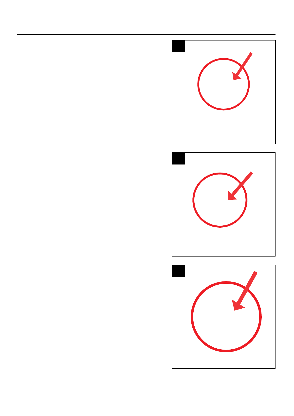
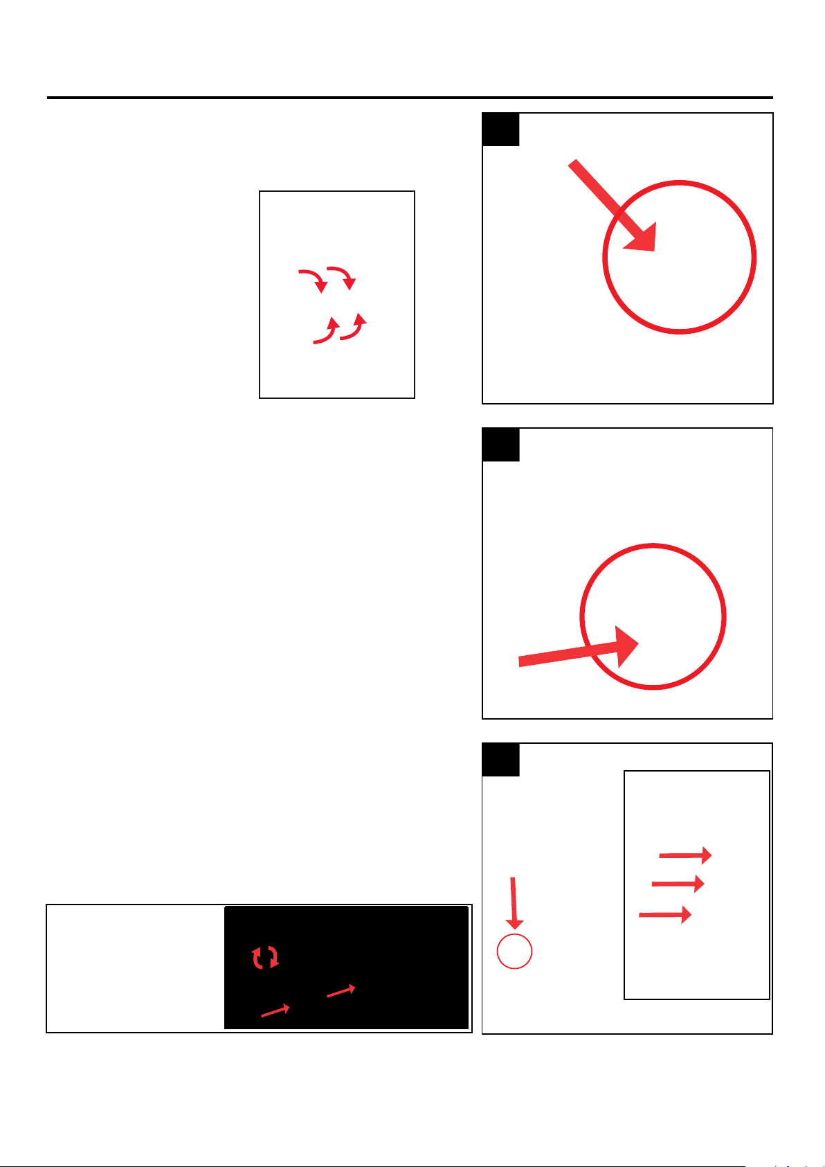
ASSEMBLY INSTRUCTIONS
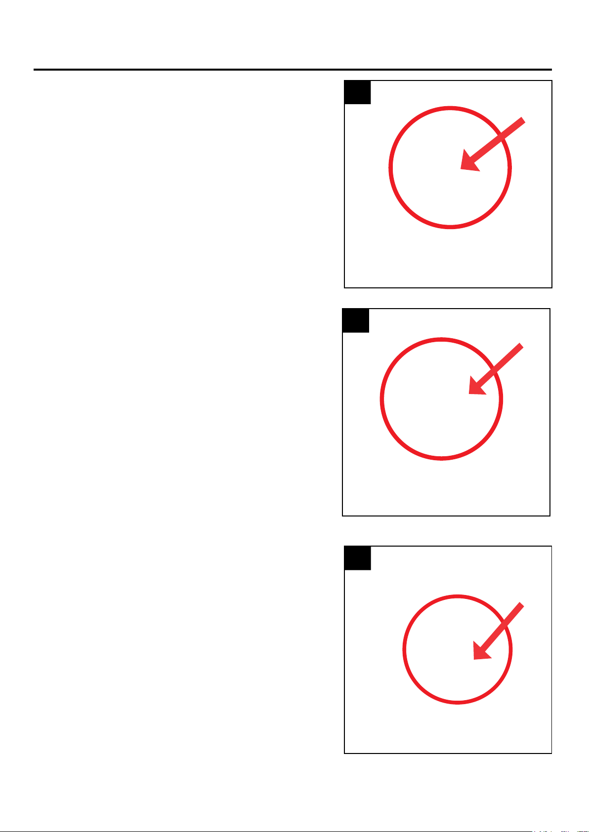
1. Insert and snap lock the lower left leg pole into the
metal base. (Match A to A)
2. Insert and snap lock the lower right leg pole into the
metal base. (Match A1 to A1)
3. Insert and snap lock the middle leg pole into the lower
left leg pole. (Match B to B)
1
2
3
Page 3
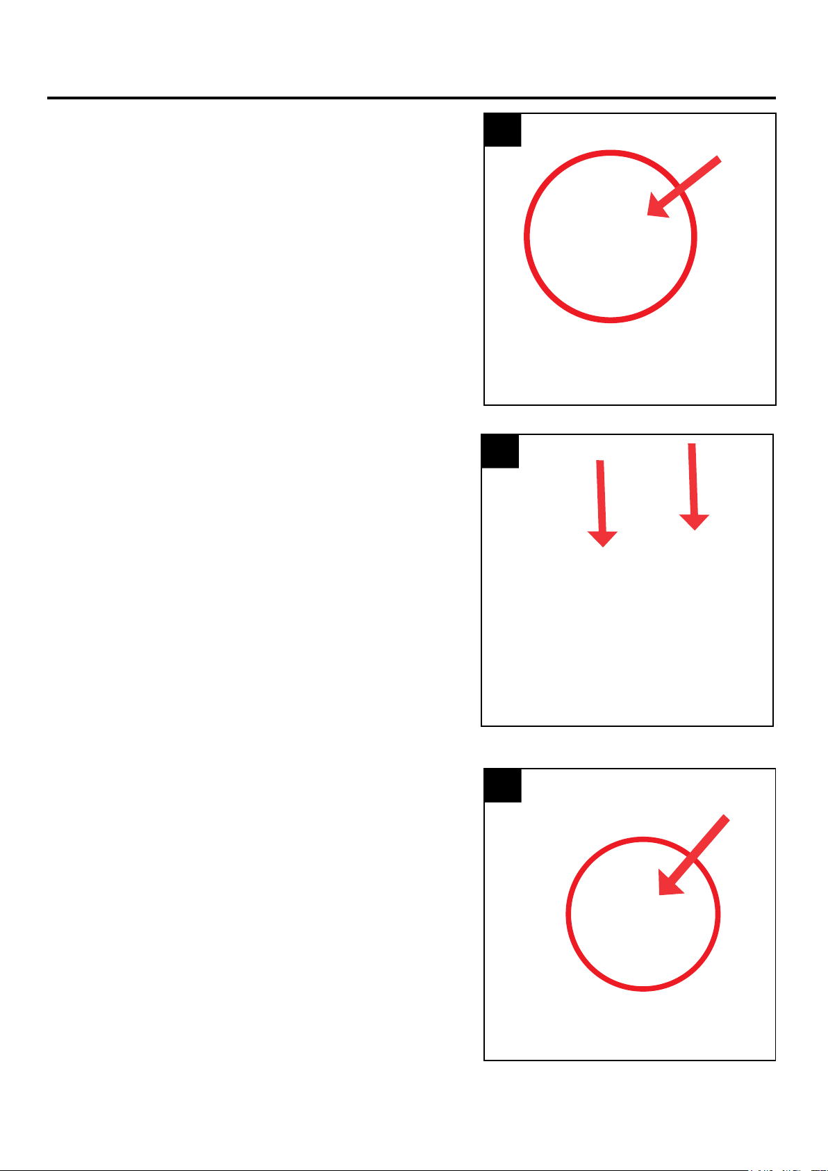
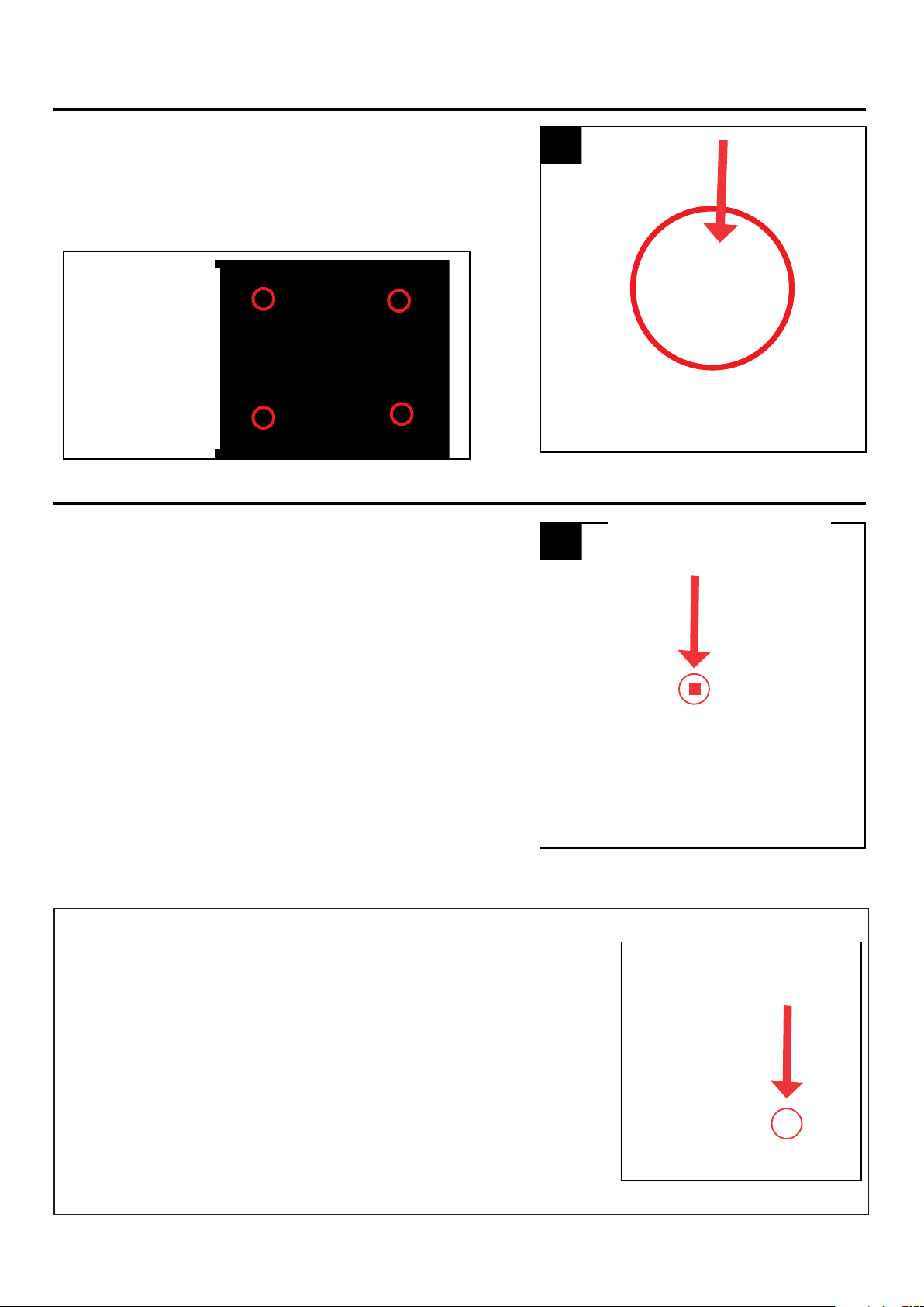
ASSEMBLY INSTRUCTIONS
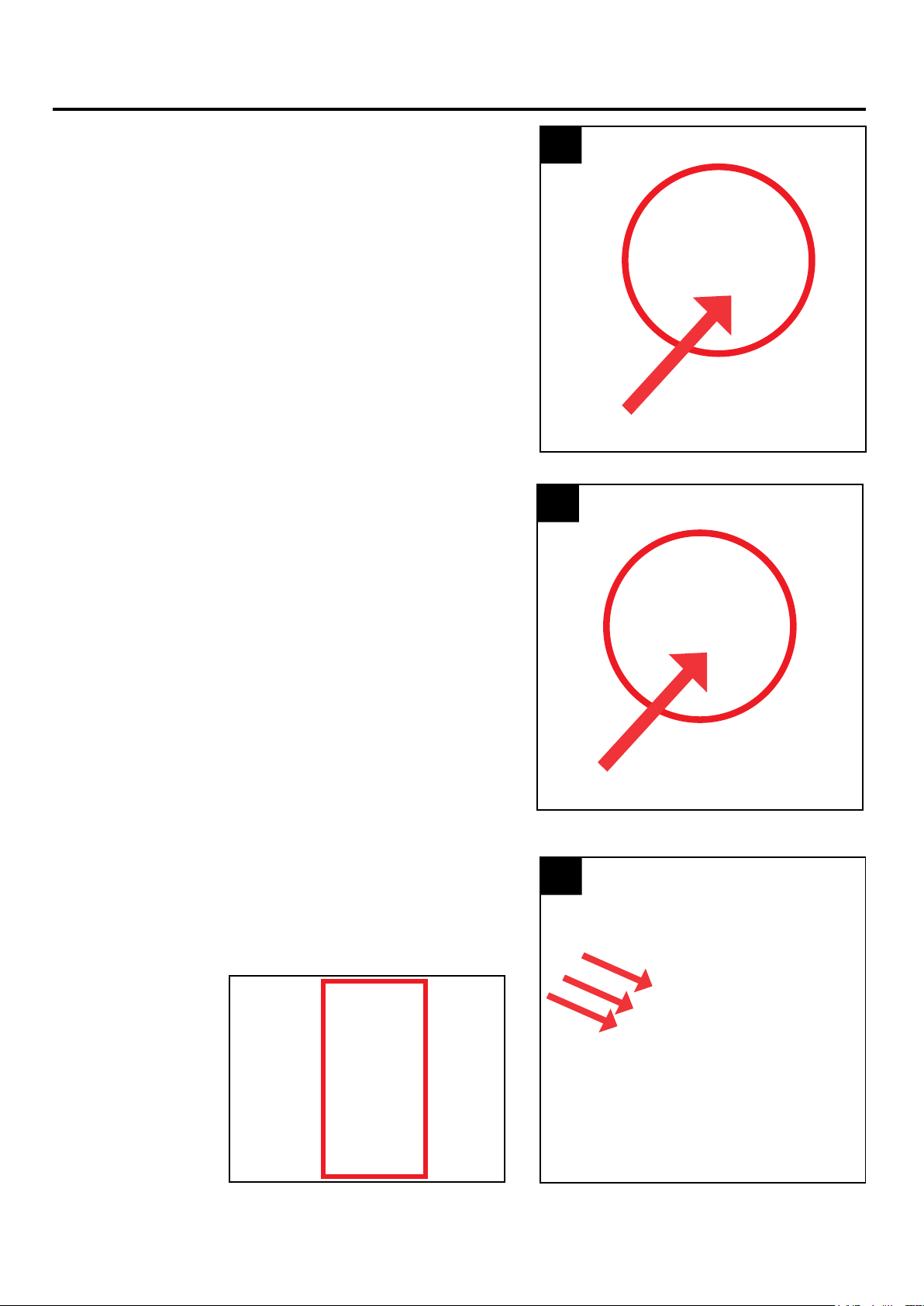
4. Insert and snap lock the middle leg pole into the lower
right leg pole. (Match B1 to B1)
6. Insert and snap lock the upper leg pole with control
box into the middle leg pole. (Match C to C)
5. Place the pants with the FRONT label facing forward
over the assembled metal base and middle leg poles.
4
6
5
Page 4

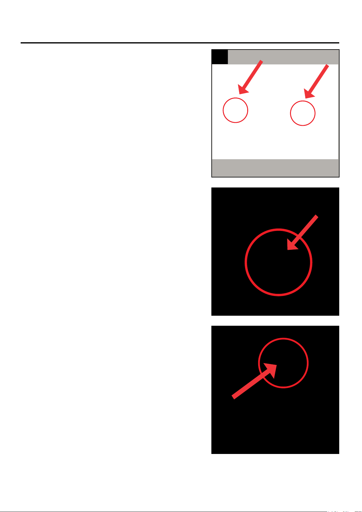
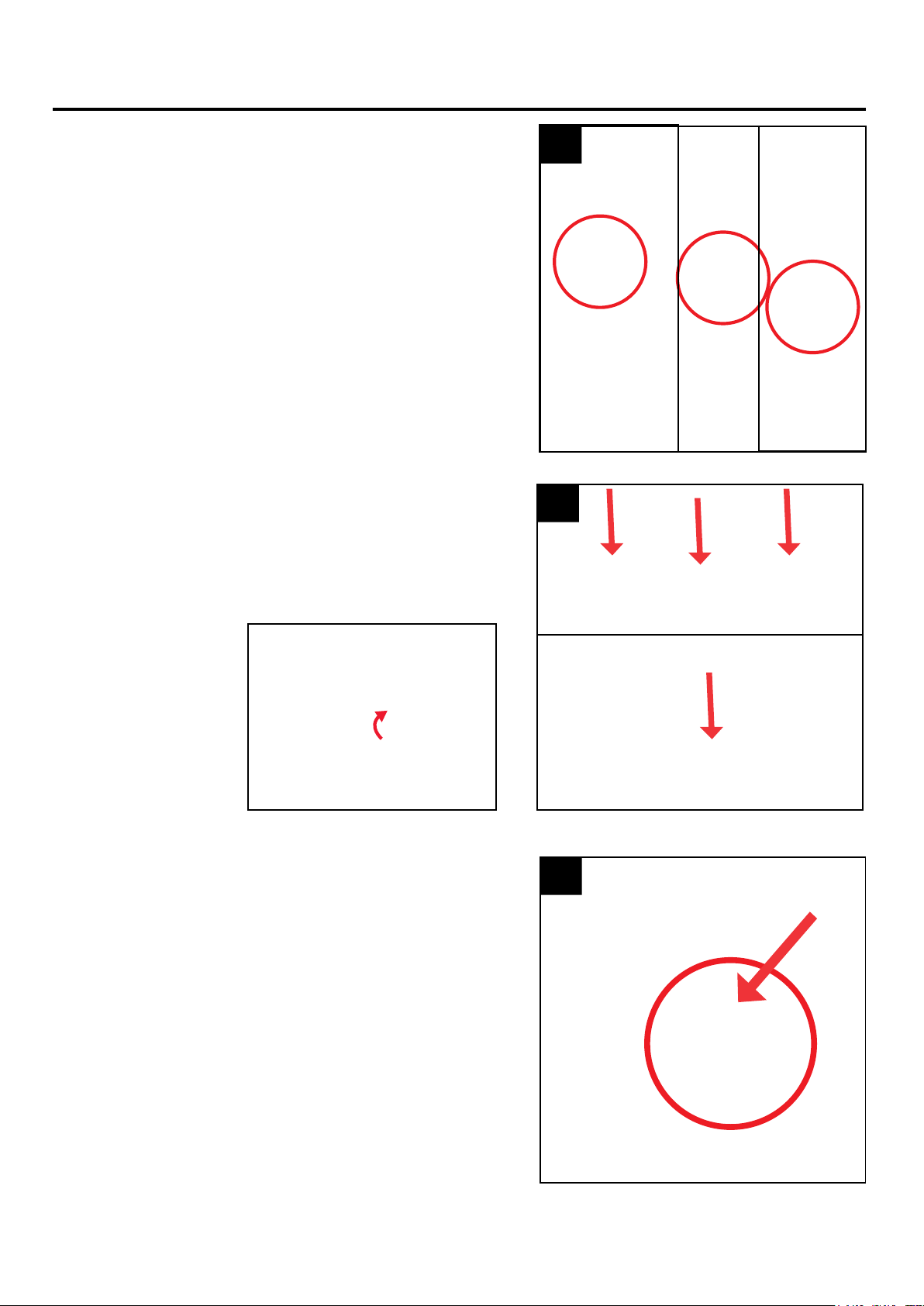
7. Insert and snap lock the upper right leg pole into the
middle leg pole.
(Match C1 to C1)
7
8. Attach the waist frame to the upper leg poles.
(Match D to D) and (Match D1 to D1)
8
9. Attach the tether lines (qty 2) and carabiners to the
waist frame.
Tip the assembled base, legs, and waist frame against
the shipping box to continue assembly.
9
Page 5
ASSEMBLY INSTRUCTIONS
ASSEMBLY INSTRUCTIONS
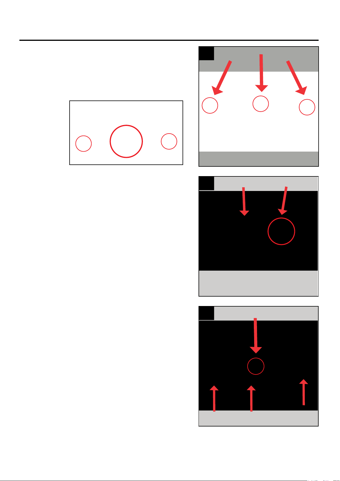
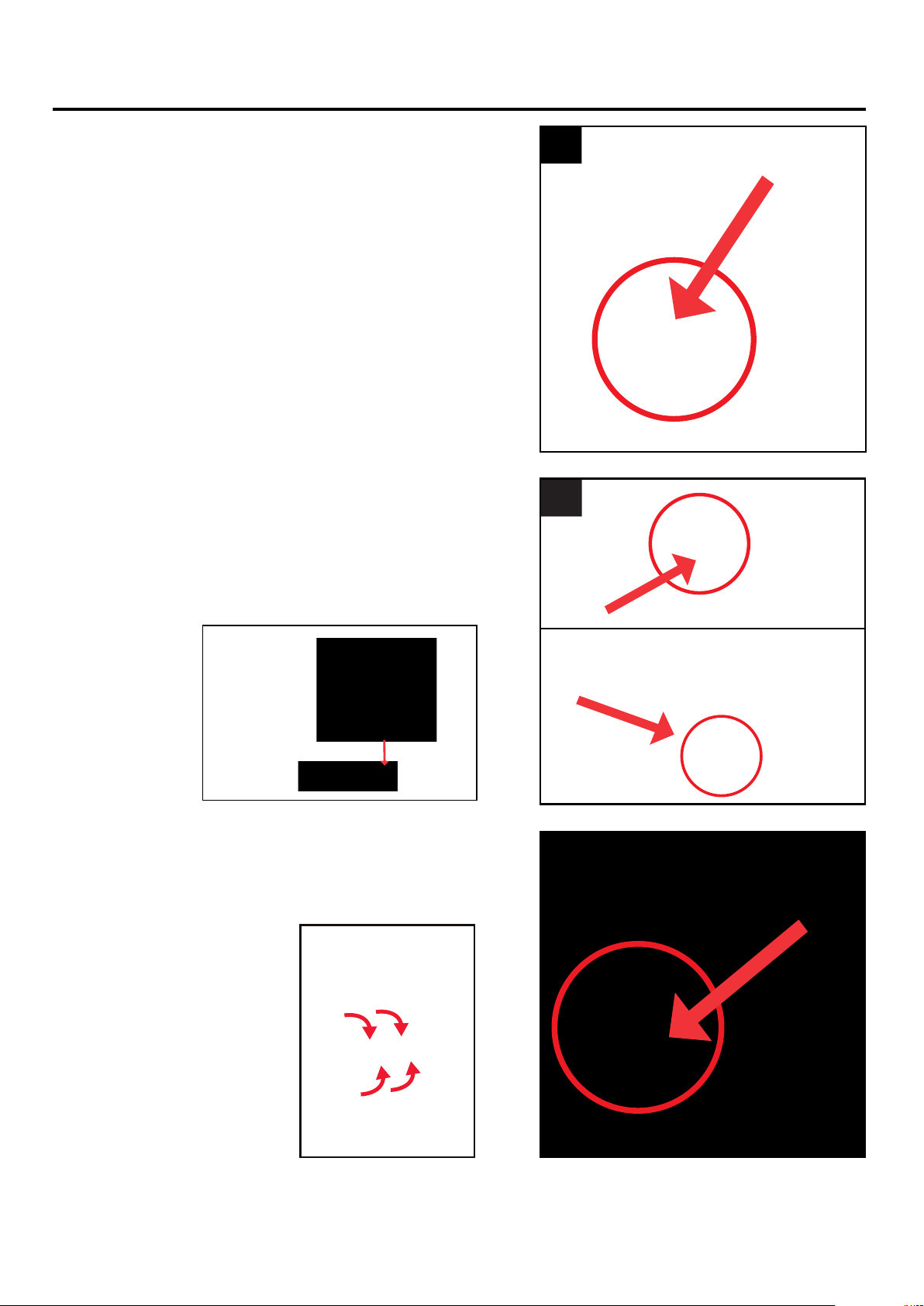
10. Insert the four posts on the waist bracket into the
waist frame.
11. Insert and snap lock the frame post and LED into the
waist frame.
(Match E to E)
12. Insert and snap lock the spine and shoulder frame
into frame post and LED.
(Match F to F)
10
11
12
Page 6
ASSEMBLY INSTRUCTIONS
13. Insert and snap lock all three posts of the rib cage to
the spine and shoulder frame.
(Match G to G) (Match H to H) and (Match I to I)
14. Insert the wire shoulder frame into the spine and
shoulder frame.
(Match red to red) and (Match blue to blue)
15. Hook the wire back frame to the wire shoulder frame.
(Match yellow to yellow)
Secure with three supplied zip ties.
13
14
15
Page 7

ASSEMBLY INSTRUCTIONS
16. Attach the tether line and carabiner to the spine and
shoulder frame.
17. Slide the shirt over the assembled wire shoulder frame
and rib cage.
18. Attach the hook and loop fasteners on the shirt to the
hook and loop fasteners on the top, bottom and sides
of the rib cage.
16
17
18
Page 8
ASSEMBLY INSTRUCTIONS
19. Insert and snap lock the head to the spine and
shoulder frame.
(Match J to J)
21. Snap lock lower left arm pole to upper left arm pole.
(Match N to N)
20. Snap lock lower right arm pole to upper right arm pole.
(Match L to L)
19
21
20
Page 9
ASSEMBLY INSTRUCTIONS
22. Slide the assembled left arm up the sleeve.
Snap lock the left arm to the spine and shoulder frame.
(Match M to M)
24. Attach straw collar around the neck and below the
head. Attach the hook and loop fastener to secure
the straw collar in place.
23. Slide the assembled right arm up the sleeve.
Snap lock the right arm to the spine and
shoulder frame.
(Match K to K)
22
24
23
Page 10
ASSEMBLY INSTRUCTIONS
25. Connect the wire from Human sensor to the wire to
the control box. (Connect T to T)
Connect the wire from the frame post and LED to the
control box. (Connect U to U)
Connect the wire from the head to the wire to the
control box. (Connect V to V)
27. Connect the middle scythe pole to the upper scythe
pole. Twist to lock.
(Match P to P)
26. Pull the pants up and attach the hook and loop
fastener around the waist frame.
Attach the hook and loop from the pants to the shirt.
Finish clothing assembly by attaching the rope hook
and loop fastener to the shirt.
25
27
26
Page 11
ASSEMBLY INSTRUCTIONS
28. Connect the lower pole to the middle scythe pole.
Twist to lock. (Match O to O)
29. Connect the blade to the upper scythe pole.
(Match Q to Q)
Secure the scythe blade by inserting the clevis pin
through the hole in the blade. Slide the cotter pin
through the hole in the clevis pin to secure and
complete the blade assembly.
30. Snap lock the scythe pole to the left arm.
(Match R to R)
Secure the hook and loop on the sleeve to the
scythe pole.
28
29
30
Page 12
CLEVIS
PIN
COTTER
PIN
ASSEMBLY INSTRUCTIONS
31. Snap lock the scythe pole to the right arm.
(Match S to S)
Secure the hook and loop on the sleeve to the
scythe pole
32. Recommended 2 people Stand the Scarecrow upright.
Insert all four base supports into the metal base.
(Match W to W)
33. Insert the 5.9V 2A adapter into the control box.
Insert fully and twist until snug (do not over tighten)
Access the control box through flap located on the
back of the left leg.
31
32
33
Page 13
NOTE: Assemble plug
end of adapter by
inserting cord and
sliding collar forward.
Turn collar clock-wise
to secure.
ASSEMBLY INSTRUCTIONS
OPERATING INSTRUCTIONS
33. Pull the 3 tether lines out and secure the ground
stakes by inserting them into the ground.
Finish the ground stake setup by securing the metal
frame with inserting four additional ground stakes in
all four corners of the frame as shown.
34. Move the switch to the ON position. Move in front of
the item or make a loud sound (clap) to activate the
item. Move the switch to the HUMAN ONLY position
to activate the item with motion only.
Turn the item to the OFF (DEMO) position when not
in use.
33
34
Page 14
OPTIONAL DEMO SET UP
1. Insert the cable from optional footpad/push button into the
jack labeled DEMO on the CONTROL BOX.
2. Place the switch in the DEMO position to enable
DEMO activation.
3. Step on the FOOTPAD or press push button to activate the
scary sequence!
Footpads and push buttons are sold separately and can be
purchased at www.tekkyaccessories.com
*
FOOTPAD/PUSH BUTTON IS NOT INCLUDED. MUST BE PURCHASED SEPARATELY.

TROUBLESHOOTING
PROBLEM POSSIBLE CAUSE CORRECTIVE ACTION
Item will not
activate.
• 5.9V 2A adapter is not plugged in.
• Switch on control box is not in the ON position.
• Human sensor on pants may be blocked.
• Check 5.9V 2A adapter is plugged in
and securely inserted into the
control box.
• Move switch to ON position.
• Move any obstructions away from the
pants.
Item has no sound while
operating.
• Volume knob is turned all the way down. • Adjust volume knob to desired volume.
You only hear
item sound but no
item activation.
• Control box wires are not connected • Check that wires labeled T, U, V, are
securely connected.
CARE AND MAINTENANCE
• STORE IN A COOL AND DRY ENVIRONMENT.
• IN INCLEMENT WEATHER BRING ITEM INDOORS.
• SURFACE WASHABLE ONLY. DO NOT USE ANY HARSH OR ABRASIVE CLEANING AGENTS.
EXTERNAL SPEAKER IS NOT INCLUDED. MUST BE PURCHASED SEPARATELY.
1. Plug speaker cord into the jack labeled SPEAKER JACK
located on the CONTROL BOX.
2. Use volume knob on external speaker to control volume levels.
OPTIONAL EXTERNAL SPEAKER SET UP
Page 15

FCC REGULATION
Printed in China
Page 16
FCC STATEMENT
FCC RULES: This device complies with Part 15 of the FCC Rules. Operation is subject to the following two
conditions: (1) this device may not cause harmful interference, and (2) this device must accept any interference
received, including interference that may cause undesired operation.
CAUTION: Changes or modications not expressly approved by the party responsible for compliance could void
the user’s authority to operate the equipment.
NOTE: This equipment has been tested and found to comply with the limits for a Class B digital device, pursuant
to Part 15 of the FCC Rules. These limits are designed to provide reasonable protection against harmful
interference in a residential installation. This equipment generates, uses, and can radiate radio frequency energy
and, if not installed and used in accordance with the instructions, may cause harmful interference to radio
communications. However, there is no guarantee that interference will not occur in a particular installation. If this
equipment does cause harmful interference to radio or television reception, which can be determined by turning
the equipment o and on, the user is encouraged to try to correct the interference by one or more of the
following measures:
• Reorient or relocate the receiving antenna.
• Increase the distance between the equipment and receiver.
• Connect the equipment into an outlet on a circuit dierent from that to which the receiver is connected.
• Consult the dealer or an experienced radio/TV technician for help.
This manual suits for next models
1
Table of contents
Other HAUNTED LIVING Home Lighting Accessories manuals


Popular Home Lighting Accessories manuals by other brands

Home Accents Holiday
Home Accents Holiday TY636-1914 Assembly instructions

HSV
HSV KS-CL106HSV operating instructions

Home Accents Holiday
Home Accents Holiday TY229+739-1614-1 Assembly instructions

Guirled
Guirled HT339R-100 user manual

Home Accents Holiday
Home Accents Holiday 23RT14122112 Assembly instructions

Goobay
Goobay LED Wire Star 3D user manual


