Gima 35134 User manual

MULTI-PARAMETER PATIENT MONITOR
M35134-GB-Rev.3-06.19
35134
Gima S.p.A.
Via Marconi, 1
20060 Gessate (MI) - Italy
Made in China
0476
Gima S.p.A.
Via Marconi, 1 - 20060 Gessate (MI) Italy
gima@gimaitaly.com - export@gimaitaly.com
www.gimaitaly.com
User Manual
ATTENTION: The operators must carefully read and completely
understand the present manual before using the product.
PROFESSIONAL MEDICAL PRODUCTS

2
This Manual is written and compiled in accordance with standards and requirements for electromedical de-
vices.
The Manual is written for the current Patient Monitor.
The Manual describes, in accordance with the Patient Monitor’s features and requirements, main structure,
functions, specications, correct methods for transportation, installation, usage, repair, maintenance and stor-
age, etc. as well as the safety procedures to protect both the user and equipment. Refer to the respective
chapters for details.
This manual it consists of two parts, part I covers almost the all necessary content, except the operations for
user interface, which is included separately in part II.
We reserve the right to improve and amend it at any time without prior notice. Amendments will however be
published in a new edition of this manual.
This manual is an integral part of the product, it should always be kept close to the equipment so that it can be
obtained conveniently when needed
Marks in the Manual
Warning: must be followed to avoid endangering the operator and the patient.
☞Note: contains some important information and tips about operations and application.
Attention: must be followed to avoid causing damage to the monitor.
Instructions to User
Dear Users,
Thank you very much for purchasing our product. Please read the following very carefully before using this
equipment.
Read these instructions carefully before using this monitor. These instructions describe the operating proce-
dures to be followed strictly. Failure to follow these instructions can cause monitoring abnormality, equipment
damage and personal injury. The manufacturer is NOT responsible for the safety, reliability and performance
issues and any monitoring abnormality, personal injury and equipment damage due to user’s negligence of the
operation instructions. The manufacturer’s warranty service does not cover such faults.
WARNING for PACEMAKER PATIENTS: Although the pacemaker pulse inhibition function is available in this
device, the heart rate meter may continue to count the pacemaker rate during occurrences of cardiac arrest
or some arrhythmias. Do not rely entirely upon rate meter ALARMS. Keep pacemaker patients under close
surveillance. See this manual for disclosure of the pacemaker pulse rejection capability of this instrument.
If uncertain about the accuracy of any measurement, rst check the patient’s vital signs by any alternative
means, and then make sure the monitor is functioning properly.
The device should be considered an early warning device. As a trend towards patient deoxygenation is
indicated, blood samples should be analyzed by a laboratory CO-oximeter to completely understand the
patient's condition.
The monitor is not suitable for use in the presence of ammable anesthetic mixture with air, oxygen or ni-
trous oxide.
Monitoring a single person at a time.
The monitor is debrillator proof. Verify that the accessories can function safely and normally and the mon-
itor is grounded properly before conducting debrillation.
Disconnect the monitor and sensors before MRI scanning. Use during MRI could cause burns or adversely
affect the MRI image or the monitor’s accuracy.
If you have any doubt to the grounding layout and its performance, you must use the built-in battery to
power the monitor.
All combinations of equipment must be in compliance with the standard IEC 60601-1.
Check SpO2probe application site periodically (every 30 minutes) to determine circulation, positioning and
skin sensitivity.
The SpO2measurement of this monitor may not work for all testees. If stable readings cannot be obtained
at any time, discontinue use.

3
Do not immerse the monitor or its accessories in liquid to clean.
Do not use accessories other than those provided/recommended by the.
Each time the monitor is used, check the alarm limits to ensure that they are appropriate for the patient
being monitored.
Do not silence the audible alarm if patient safety may be compromised.
The alarm limit value shall be within the measuring range, or it may disable the alarm system. Please refer
to the related chapter for alarm limit range.
A HAZARD can exist if different alarm presets are used for the same or similar equipment in single area.
The monitor is intended only as an adjunct in patient assessment. It must be used in conjunction with clin-
ical signs and symptoms.
When taking the measure of a pediatric or neonates(less than 10 years old) blood pressure, do NOT operate
in the adult mode. The high ination pressure may cause lesion or even body putrescence.
The monitor is prohibited from applying to those who have severe hemorrhagic tendency or who are with
sickle cell disease for they may develop partial bleeding when this monitor is used to take the blood pres-
sure measurement.
DO NOT take blood pressure measurement from a limb receiving ongoing transfusion or intubations or skin
lesion area, otherwise, damages may be caused to the limb.
Continuous use of SpO2sensor may result in discomfort or pain, especially for those with microcirculatory
problem. It is recommended that the sensor should NOT be applied to the same place for over two hours,
change themeasuring site periodically if necessary.
SpO2measuring position must be examined more carefully for some special patient. Do NOT install the
SpO2sensor on the nger with edema or vulnerable tissue.
To prevent the risk of the short circuit and to ensure the ECG signal quality, the equipment must be properly
grounded.
Although biocompatibility tests have been performed on all the applied parts, some exceptional allergic
patients may still have anaphylaxis. Do NOT apply to those who have anaphylaxis.
All the connecting cables and rubber tubes of the applying parts should be kept away from the patient's
cervix to prevent any possible suffocation of the patient.
All the parts of the monitor should NOT be replaced at will. If necessary, please use the components pro-
vided by the manufacturer or those that are of the same model and standards as the accessories along
with the monitor which are provided by the same factory, otherwise, negative effects concerning safety and
biocompatibility etc. may be caused.
DO NOT stare at the light of SpO2sensor (infrared is invisible) when switch it on, for the infraredmay do
harm to the eye.
If the monitor falls off accidentally, please do NOT operate it before its safety and technical indexes have
been tested minutely and positive testing results obtained.
The system might not meet its performance specications if stored or used outside the manufacturer’s
specied temperature and humidity ranges.
Reuse, disassembly, cleaning, disinfecting the single patient use CO2cannula kits and on-airway adapters
may compromise functionality and system performance leading to a user or patient hazard. Performance is
not guaranteed if an item labeled as single patient use is reused.
Electrical Shock Hazard: Always disconnect the CO2Sensor before cleaning. Do NOT use if it appears to
have been damaged. Refer servicing to qualied service personnel.
Electrical Shock Hazard:No user serviceable parts inside the CO2Sensor.
After the life cycle of the Sidestream CO2Sensor and its accessories has been met, disposal should be
accomplished following national and/or local requirements.
Please peruse the relative content about the clinical restrictions and contraindication.
The accessories which can be used repeatedly should have a thorough cleanness before it is used to an-
other patient. Please refer to the related chapter for maintenance method.
When disposing of the monitor and its accessories, the local law should be followed.
Substitution of a component different from that supplied might result in measurement error.

4
INDEX PART I
Chapter 1 Overview ...................................................................................................................................... 7
1.1 Product Name......................................................................................................................... 7
1.2 Applications and Scope.......................................................................................................... 7
1.3 Operating Environment........................................................................................................... 7
1.4 Impact on Environment and Resources.................................................................................. 7
1.5 Safety...................................................................................................................................... 7
Chapter 2 Working Theories........................................................................................................................ 8
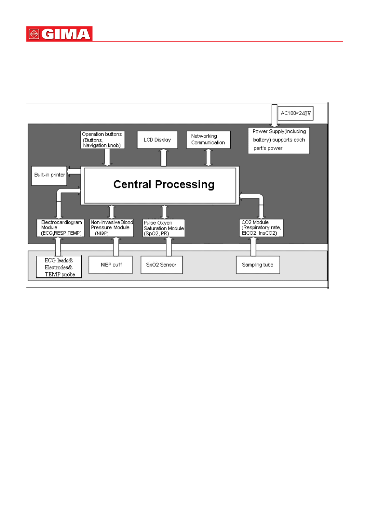
2.1 Overall Structure..................................................................................................................... 8
2.2 Composition ........................................................................................................................... 8
2.3 Working Theories .................................................................................................................... 8
Chapter 3 Installation and Connection....................................................................................................... 9
3.1 Installation............................................................................................................................... 9
3.1.1 Opening the Box and Check.......................................................................................... 9
3.1.2 Connecting the AC Power Cable ................................................................................... 9
3.1.3 Starting the Monitor ..................................................................................................... 10
3.2 Connection ........................................................................................................................... 10
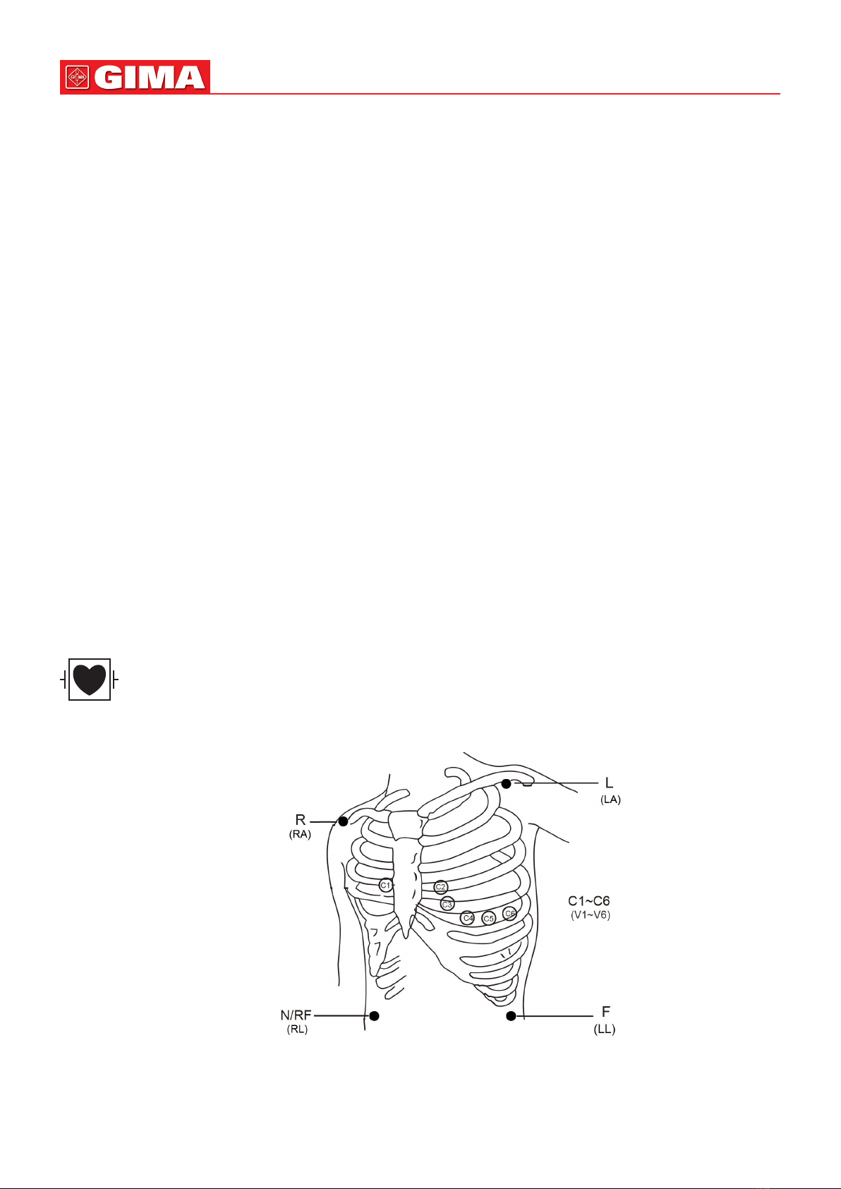
3.2.1 ECG Cable/Lead Wires Connection............................................................................. 10
3.2.2 Cuff Connection for Blood Pressure Measurement ..................................................... 12
3.2.3 SpO2Probe Connection.............................................................................................. 14
3.2.4 CO2 Sensor Connection .............................................................................................. 17
3.2.5 TEMP Probe Connection ............................................................................................. 20
3.2.6 Loading Printing Paper ................................................................................................ 21
Chapter 4 Alarm.......................................................................................................................................... 22
4.1 Alarm Description ................................................................................................................. 22
4.1.1 Alarm Condition ........................................................................................................... 22
4.1.2 Alarm Priority................................................................................................................ 22
4.1.3 Alarm Modes................................................................................................................ 23
4.1.4 Alarm Setting ............................................................................................................... 23
4.2 Alarm Technical Specications ............................................................................................. 23
Chapter 5 Technical Specications .......................................................................................................... 24
5.1 ECG Monitoring .................................................................................................................... 24
5.2 RESP Monitoring .................................................................................................................. 25
5.3 TEMP Monitoring .................................................................................................................. 25
5.4 NIBP Monitoring ................................................................................................................... 25
5.5 SpO2 Monitoring................................................................................................................... 26
5.6 Pulse Rate Monitoring .......................................................................................................... 26
5.7 CO2 Monitoring .................................................................................................................... 26
5.8 Data Recording..................................................................................................................... 26
5.9 Other Technical Specications ............................................................................................. 26
5.10 Classication....................................................................................................................... 26
5.11 Guidance and manufacturer’s declaration - Electromagnetic compatibility....................... 27
Chapter 6 Packaging and Accessories .................................................................................................... 29
6.1 Packaging ............................................................................................................................. 29
6.2 Accessori .............................................................................................................................. 29
Chapter 7 Working Principles.................................................................................................................... 30
7.1 Introduction to ECG Measurement ....................................................................................... 30
7.1.1 How to Obtain High Quality ECG and Accurate Heart Rate Value .............................. 30
7.1.2 Factors affecting ECG signal ....................................................................................... 30
7.2 Introduction to Blood Pressure Measurement...................................................................... 31
7.2.1 Blood Pressure Measuring Principle............................................................................ 31
7.2.2 Factors affecting NIBP measuring ............................................................................... 32
7.2.3 Clinical Limitations ....................................................................................................... 32
7.3 Introduction to Oxygen Saturation Measurement................................................................. 33
7.3.1 SpO2Measuring Principle ........................................................................................... 33
7.3.2 SpO2Measurement Restrictions (interference reason) ............................................... 33
7.4 Introduction to Respiration Measurement ............................................................................ 34
7.4.1 Respiration Measuring Principle .................................................................................. 34
7.4.2 Factors affecting respiration monitoring ...................................................................... 34
7.5 Introduction to Temperature Measurement .......................................................................... 34

5
7.6 Introduction to Capnograph Measurement .......................................................................... 34
7.6.1 CO2 Measuring Principle ............................................................................................. 34
7.6.2 Mainstream vs. Sidestream Sampling ......................................................................... 34
Chapter 8 Troubleshooting ........................................................................................................................ 35
8.1 No Display on the Screen ..................................................................................................... 35
8.2 Excessive ECG Signal Interference or too Thick Baseline.................................................... 35
8.3 No Blood Pressure and Pulse Oxygen Measures................................................................. 35
8.4 System Alarm........................................................................................................................ 35
Chapter 9 Maintenance.............................................................................................................................. 35
9.1 Service and Examination ...................................................................................................... 35
9.1.1 Daily Examination......................................................................................................... 35
9.1.2 Routine Maintenance ................................................................................................... 36
9.2 Battery Maintenance............................................................................................................. 36
9.3 Cleaning and Disinfection of the Device............................................................................... 36
9.4 Cleaning and Disinfection of Accessories ............................................................................ 37
9.5 Storage ................................................................................................................................. 37
9.6 Transportation....................................................................................................................... 37
Chapter 10 Appendix.................................................................................................................................... 38
10.1 Alarm Information ............................................................................................................... 38
10.2 Default Alarming Values and Setup Range......................................................................... 39
10.3 Status/Error during NIBP Monitoring.................................................................................. 41
10.4 Status/Error during CO2Monitoring................................................................................... 42
10.5 Typical Pressures and CO2Readings at Altitudes ............................................................. 43
10.6 Accessories List.................................................................................................................. 43
INDEX PART II
Chapter 1 Overview .................................................................................................................................... 44
1.1 Features ................................................................................................................................ 44
1.2 Introduction to Panels........................................................................................................... 45
1.2.1 Front Panel................................................................................................................... 45
1.2.2 Left and Right Panel..................................................................................................... 46
1.2.3 Rear Panel.................................................................................................................... 47
Chapter 2 Screen Display .......................................................................................................................... 47
2.1 Default Screen Display.......................................................................................................... 47
2.1.1 Date and Time Setup ................................................................................................... 47
2.1.2 Screen Description....................................................................................................... 48
2.3 Screen Display for Remote Observation .............................................................................. 51
2.3.1 Screen Description....................................................................................................... 51
2.3.2 NIBP Screen Display.................................................................................................... 51
2.3.3 Screen Display with ECG Waveforms only .................................................................. 52
2.3.4 Five Channels Real-time Waveforms and Trends on the Same Screen....................... 53
2.3.5 Parameter Screen ........................................................................................................ 54
2.4 ECG Waveform Freezing and S-T Segment Measurement .................................................. 55
2.4.1 Screen Description....................................................................................................... 55
2.4.2 Operating Instructions ................................................................................................. 55
Chapter 3 Screen Display for System Menu ............................................................................................ 56
3.1 System Menu Screen............................................................................................................ 56
3.1.1 How to Select the Menu Item ...................................................................................... 56
3.2 SpO2 Trend Data List Screen ............................................................................................... 56
3.2.1 Screen Description....................................................................................................... 57
3.2.2 Operating Instructions ................................................................................................. 57
3.3 NIBP Data List Screen .......................................................................................................... 57
3.3.1 Screen Description....................................................................................................... 57
3.3.2 Operating Instructions ................................................................................................. 57
3.4 Screen Display for Graphic Trend ......................................................................................... 57
3.4.1 How to View the Graphic Trend ................................................................................... 58
3.4.2 Operation Instructions ................................................................................................. 59

6
3.5 Screen Display for Waveform Recall .................................................................................... 60
3.5.1 Operation Instructions ................................................................................................. 60
3.6 Screen Display for Arrhythmia Event List ............................................................................. 61
3.6.1 Operation Instructions ................................................................................................. 61
3.7 Screen Display for System Setting ....................................................................................... 62
3.7.1 How to Select the System Setup Item......................................................................... 62
3.7.2 Parameter Settings ...................................................................................................... 62
3.8 Display Color Settings .......................................................................................................... 66
3.8.1 How to Change the Parameter Color........................................................................... 67
3.9 File Management Screen...................................................................................................... 67
3.9.1 How to Add a New Patient........................................................................................... 67
3.10 oxyCRG Screen .................................................................................................................. 67
3.10.1 Operation Instructions ............................................................................................... 68
3.11 Event List Screen................................................................................................................ 68
3.11.1 Screen Description..................................................................................................... 68
3.11.2 Operating Instructions ............................................................................................... 68
3.12 MC Calculator..................................................................................................................... 68
3.12.1 Medicine Dosage Calculator...................................................................................... 68
3.13 Tourniquet Function ............................................................................................................ 70
3.13.1 Operation Instructions ............................................................................................... 70
Chapter 4 CO2 Monitoring (optional) ....................................................................................................... 70
4.1 CO2 Related Settings ........................................................................................................... 70
4.2 CO2 Monitoring Screen ........................................................................................................ 73
4.3 CO2 Graphic Trend ............................................................................................................... 74

7
PART I
Chapter 1
OVERVIEW
1.1 Product Name
Name: MULTI-PARAMETER PATIENT MONITOR
1.2 Applications and Scope
This Patient Monitor is a multi-functional instrument designed for monitoring the vital physiological signs of
adult and pediatric patients. With the functions of real-time recording and displaying parameters, such as ECG,
heart rate, non-invasive blood pressure, functional oxygen saturation, end-tidal CO2concentration, respiration
rate, body temperature, and so on, it allows comprehensive analysis of patient’s physiological conditions.
This instrument is applicable for use in hospitals and clinical institutions. The operation should be performed
by qualied professionals only.
1.3 Operating Environment
1. Ambient temperature range: 5°C~40°C
Relative humidity: 30%~80%
Atmospheric pressure: 70kPa ~106.0kPa
Power Voltage: (100-240)VAC
Power frequency: 50Hz/60Hz
2. This equipment should be situated in a place protected against direct sunlight, so as to prevent overheating
inside the equipment.
3. The device should be stored and used within specied temperature, humidity and atmospheric pressure
range, or it may cause damage to the device or inaccurate measurement result.
4. If the device gets wet by accident, the operator should NOT power it on directly until it has been air-dry
enough to avoid any damage to it.
5. Do not use this equipment in an environment with toxic or inammable gas.
6. This equipment should be placed on a stand or at platforms, so as to prevent possible shock.
7. Do not use this equipment in combination with any equipment other than those expressly permitted in the
manual.
8. The monitor is debrillator discharge proof and can be used with electrosurgical unit. But when the device
is used together with debrillator or electrosurgical equipment, the user (doctor or nurse) should keep the
patient under close surveillance for his/her safety. Refer to the following function description for specic
protective measures or notes.
9. Make sure that the equipotential grounding terminal is grounded correctly.
10.Do not use mobile phone nearby, so as to avoid strong radiant eld interference.
1.4 Impact on Environment and Resources
Low
1.5 Safety
a) This device conforms to IEC60601-1, electric safety classication: Class I, with Type BF and CF applied
parts.
b) This device can resist against the discharge of debrillator and the interference of electrosurgical unit. c) .
This device can monitor the patients with pace-maker.
d) DO NOT use this device while the patient is under MRI scanning.

8
Chapter 2
WORKING THEORIES
2.1 Overall Structure
The overall structure of the monitor is shown as Figure 2.1
Figure 2.1
2.2 Composition
1. The monitor consists of the main units and the corresponding functional components (ECG cables/lead
wires, non-invasive blood pressure cuff, SpO2probe, temperature transducer, accessories for invasive
blood pressure and CO2monitoring).
2. The patient monitor has multiple measurement channels including ECG/Heart Rate, NIBP, SpO2/Pulse Rate,
Respiration Rate, Temperature, and CO2Concentration.
3. The patient monitor has output ports including networking communication and the built-in printer.
4. Basic conguration includes the functions of ECG/Heart Rate, NIBP (systolic, diastolic, mean aterial pres-
sure & pulse rate), SpO2/Pulse Rate, Respiration Rate, and Temperature.
2.3 Working Theories
This Patient Monitor, which performs physiological parameter measurement through different modules, is a
product with modular design. It consists of several modules: ECG/RESP/TEMP module, NIBP module, SpO2
module, CO2module (optional), the mother board and other auxiliary boards
1. The ECG/RESP/TEMP module detects the ECG signal through ECG cable/lead wires via electrodes, it also
measures the respiration by use of the same ECG electrodes. The temperature is measured through the
temperature probe. The heart rate and respiration rate are calculated from its signal waveform respectively.
2. The SpO2module detects the plethysmograph data via the SpO2probe and calculates the pulse rate and
oxygen saturation (SpO2) accordingly.
3. The NIBP module measures the blood pressures including systolic, diastolic, mean arterial pressure and
pulse rate through the pneumatic system and cuff. The cuffs are designed for adult and pediatric patients
respectively, and it can work in different modes to adapt different patient categories.
4. The CO2module detects CO2concentration through the sampling line (side stream) or within the airway
(main stream), and calculate the respiration rate, end tidal CO2concentration (EtCO2), and inspired CO2
concentration (InsCO2).

9
5. The mother board is the main controlling unit, which also connects to the interface board and key board.
The interface board inter-connects the functional modules with the mother board.
Chapter 3
INSTALLATION AND CONNECTION
3.1 Installation
3.1.1 Opening the Box and Check
1. Open the package, take out the monitor accessories from the box carefully and place it in a safe stable and
easy to watch position.
2. Open the user manual to sort the accessories according to the packing list
• Inspect the accessories for any mechanical damages
• Check all the exposed leads and inserted accessories
• Check whether any risk or abnormity exists in the device and its accessories before using the monitor. If
any abnormity (such as broken cable or crack of the enclosure etc.) is found, stop using this device.
☞The user can customize the module conguration by choosing necessary modules to meet your own needs.
Therefore, your monitor may not have all the monitoring functions and accessories.
Please contact the local dealer or our company in case of any problems. We will offer the best solution for
your satisfaction.
3.1.2 Connecting the AC Power Cable
1. When powered by AC mains power supply:
• Make sure that the AC power supply is (100-240)VAC, 50Hz/60Hz.
• Use the power cable provided by the manufacturer. Insert one end of it to the AC power input of the monitor
and the other end to the three-pin outlet of the power source with protected-earth.
• It's required that the user should use the 3pin mains power outlet with the protected earth. If there is any
doubt with the mains power outlet for the protected earth, the user should use the built-in battery and dis-
connect the power cord to ensure electrical safety.
NOTE: The optionally provided grounding wire is for functional grounding purpose, which is used to reduce
the power line frequency noise or eliminate the potential difference while connecting the monitor to other
device, so making the system with equipotential grounding.
After the mains power supply has been interrupted while the power switch of the device remains in the “on”
position and the mains power supply is restored after a period of time that is longer than 30 seconds, the
monitor will run by the last settings when restarting the monitor.
The monitor is applicable to connect to the public mains power network.
Caution: ensure that the monitor is rmly connected to the mains power supply with protected earth.
2. Built-in battery
The following steps should be followed to install the battery:
Step 1: open the battery cover;
Step 2: pull out the battery cable and connect it to the battery pack;
Step 3: push the battery pack into the battery compartment and lock it;
Step 4: close the battery cover.
• Caution: it’s better to recharge the battery after it is used up, and the charging time should be 13~15 hours
long.
• Battery life: Provided that a battery is new and fully charged, the minimal working time of the monitor with
accessories connected is declared in the table below:
• NOTE: It will take 12-15 hours to charge battery from exhaust state to 90% charged.
The provided battery of the monitor must be recharged after transportation or storage. So if the monitor is
switched on without being connected to the AC power supply, it may not work properly due to insufcient
battery power.
Name Battery life
MULTI-PARAMETER PATIENT MONITOR 120 min

10
3.1.3 Starting the Monitor
The system performs self-test and enters initial display after switch on the monitor, and the alarm rings to in-
form that the user can begin operating it.
• Check all the applicable functions to make sure that the monitor works normally.
• If the built-in battery is applied, please recharge it after using the monitor to ensure sufcient power storage.
It will take at least 8 hours to charge battery from depletion to 90% charge.
Do not use the monitor to monitor the patient if there are indications of damage or reminders of error.
Please contact the local dealer or our company.
Start the monitor again 1 minute later after it is switched off.
3.2 Connection
3.2.1 ECG Cable/Lead Wires Connection
ECG measurement is to collect the ECG signal via the ECG electrodes. Electrode connects the patient and
the lead wires and/or ECG cable. The lead wires and/or cable connect to the monitor. The locations of the
electrodes are very important for obtaining accurate ECG signals.
1. Connect the cable to the connector marked with the “ECG" icon on the signal input panel.
2. Select electrodes to be used. Use only one type of electrode on the same patient to avoid variations in elec-
trical resistance. For ECG monitoring, it is strongly recommended to use silver/silver chloride electrodes.
When dissimilar metals are used for different electrodes, the electrodes may be subject to large offset po-
tentials due to polarization. Using dissimilar metals may also increase recovery time after debrillation.
3. Prepare the electrode sites according to the electrode manufacturer’s instructions.
4. Skin clean
Clean and scrap skin to ensure low sensor impedance if necessary. Mild soap and Water is recommended
as a skin cleanser.
NOTE: If alcohol is used as cleanser, it is recommended to have 30-second dry time for a better con-
nection.
Scraping the skin gently with a dry wash cloth, gauze, for skin preparation is helpful to remove the non-con-
ductive skin layer.
The symbol indicates that the cable and accessories are designed to have special protection against
electric shocks and is debrillator-proof.
The locations of the electrode are in the following Figure:
Figure 3.5 Electrode Location
NOTE: If any side-effect such as allergic or itchy reaction is found, remove the electrodes from the patients
immediately.
5. After starting the monitor, if the electrodes become loose or disconnected during monitoring, the system
will display “LEAD OFF” on the screen to alarm the operator.

11
It might not display ECG waveform when using ECG cable with 3 lead wires while the setting of “Ca-
ble” is set as “5” in the ECG parameter setup menu. The ECG cable with 5 leads wires should be used
to measure ECG signal at this situation.
6. The ECG leads and their corresponding locations are as follows:
Safety Instructions for ECG Monitoring
Patient Monitor can only be equipped with ECG cable and/or lead wires provided by our company; using
ECG cable and/or lead wires supplied by other companies may cause improper performance or poor pro-
tection while using debrillator.
Using the same type of qualied and authorized electrodes which should be within its effective life on
the same patient. If any side-effect such as allergic or stimulus skin is found, the measurement should be
stopped at once. It is prohibited to apply the electrode to the patient with lesion and body putrescence.
To the patient with pacemaker, due to that this device has been designed to provide function of pacemak-
er pulse inhibition for heart beat identication, normally the pacemaker pulse is not counted in heart rate
measurement and calculation, but when the pulse width of the pacemaker pulse is larger than 2ms, the
pacemaker pulse inhibition may not be fully effective. In order to reduce this possibility, observe the ECG
waveforms on the screen carefully and do NOT rely entirely on the heart rate display and alarm system of
this monitor when monitoring this kind of patients. Keep pacemaker patient under close surveillance.
The improper connection with electrosurgical unit may not only cause burns, but also damage the monitor
or arouse deviations of measurement. You can take some steps to avoid this situation, such as do NOT use
small ECG electrodes, choosing the position which is far away from the estimated Hertzian waves route,
using larger electrosurgical return electrodes and connecting them with the patient properly.
Electric parts of electrodes, leads and cable are forbidden to contact any other conductive parts (including
ground).
Patient Monitor can resist against debrillator and electrosurgical unit. Readings may be inaccurate for a
short time after or during using debrillator or electrosurgical unit.
Transient caused by cable circuitry blocks while monitoring may be similar to the real heartbeat waveform,
as a result resistance heart rate alarm rings. If the electrodes and cable are located in proper places ac-
cording to this manual’s instructions and the instructions for using electrode, the chance of this transient
occurrence will be decreased.
Electrode connection 1
(IEC Standard)
Electrode connection 2
(AHA Standard)
Electrode position on body surface
Color code Label
on lead wire
connection
Color code
Label
on lead wire
connection
Red R White RA Right Arm: The intersection between the
centerline of the right clavicle and Rib 2
Yellow L Black LA Left Arm: The intersection between the
centerline of the left clavicle and Rib 2
Green F Red LL Left Leg: Left part of the upper abdomen
Black N/RF Green RL Right Leg: Right part of the upper abdomen
White C Brown V Any of the following location (C1-C6 or V1-V6)
on chest
White/red C1 Brown V1 4th Intercostal (IC) space at right border
of sternum
White/yellow C2 Brown/
yellow V2 4th IC space at left border of sternum
White/green C3 Brown/
green V3 Midway between V2 and V4
White/brown
(blue) C4 Brown/blue V4 5th IC space on left midclavicular line
White/black C5 Brown/red V5
Left anterior axillary line at the horizontal level
of V4
White/purple C6 Brown/
purple V6
Left midaxillary line at the horizontal level of
V4

12
ECG cable and/or lead wires may be damaged while using debrillator. If the cable and/or lead wires are
used again, please do the functional check rstly.
When the monitor is inoperable due to overload of ECG or saturation of any part of the amplier, it will
prompt “Lead off” to remind operator.
The user should ensure that no predictable hazard will be caused by the summation of leakage currents
when several item of monitor are interconnected.
When plugging or unplugging the ECG cable, be sure to hold the head of the connector and pull it out.
3.2.2 Cuff Connection for Blood Pressure Measurement
1. Connect the tube with cuff to the connector marked with “NIBP” icon on the signal input panel.
2. Unfold the cuff and wrap it around the patient’s upper arm.
Requirements of the cuff:
1) Appropriate cuff should be selected according to the age and arm circumference of the subject. Its width
should be 2/3 of the length of the upper arm. The inatable part should be long enough to permit wrapping
appropriately 80% of the limb.
NOTE: the appropriate cuff should be selected according to the age and arm circumference of the patient.
2) When putting on the cuff, unfold and wrap it around the upper arm evenly to appropriate tightness.
3) Remember to empty the residual air in the cuff before the measurement is commenced.
4) Locate the cuff in such a way that the artery mark “ ” is at a location where the clearest pulsation of bra-
chial artery is observed.
5) The cuff should be tightened to a degree where insertion of one nger is allowed.
6) The lower end of the cuff should be 2cm above the elbow joint.
Figure 3.6 Cuff location
The symbol indicates that the cable and accessories are designed to have special protection against
electric shocks, and is debrillator proof.
Pressure Accuracy Verication
Pressure Accuracy Verication is a function to inspect the accuracy of pressure measurement by the NIBP
module inside the device. Technician or equipment manager should do pressure accuracy verication every
half year or year in order to check if the pressure measurement still conforms to the requirement of product
performance. If the deviation is beyond the declared specication, it is permitted to return it to factory for
repair or calibration.
Before verication, please connect the monitor to a precision pressure meter as the reference equipment
like a mercury pressure meter.

13
Figure 3.7 Connection of Pressure Accuracy Verication Fixture
Mode 1: Automatic ination for the pressure accuracy verication
At this mode, the monitor can activate the ination, so the pressure will increase automatically until it exceeds
the limit value specied in table A. This pressure limit value depends on the patient type selection as shown
in table A:
Table A
During the ination, the Monitor will close the deating valve, and the pressure value will be shown during the
process. If there is no manual deation operation, the pressure will persist until deation by manual operation,
so it is necessary to use a manual valve for doing adequate deation in several steps to verify the pressure
accuracy in the full scale of measurement range.
Mode 2: Manual ination for the pressure accuracy verication.
At this mode, the pressure should be increased manually by a pumping balloon, and the verication can be
done by applying different pressure value manually. If the increased pressure exceeds the given limit as shown
in table B, the Monitor will deate automatically because of over-pressure protection.
Table B
After the verication, do press the button again to return to normal working mode, then continue other op-
eration, or the NIBP key will be invalid.
Pressure accuracy verication must be operated by technician or equipment manager. Doctor or nurse is
not allowed to do the verication, it is very dangerous especially when the pressure cuff is still on patients.
Adult 240mmHg
Pediatric 200mmHg
Neonate 120mmHg
Adult 300mmHg
Pediatric 240mmHg
Neonate 140mmHg
Module
testing
software
Air tube
NIBP cuff with dual air tube
Inside the monitor
Manual valve
Air vent
Air tube
Air tube
Ination
balloon
Increase the pressure
manually through the
inatable balloon
NIBP
module
Mercury blood
pressure meter
Air tube

14
Air Leakage Check
In order to avoid signicant error of blood pressure measurement or even no measurement result caused
by air leakage in the pneumatic system including the cuff during measuring, it is recommended to check if
there is leak in the pneumatic system as well.
Please remove the cuff from patient while performing the leakage check.
Safety Instructions for NIBP Measurement
When taking the blood pressure measurement on a Pediatric or Neonate patient, do NOT operate in the
Adult mode. The high ination pressure may cause lesion or even body putrescence. Even though the
monitor can identify the cuff type so it will stop ination and indicate "wrong cuff" when taking the blood
pressure measurement for a pediatric or neonate in the "adult" patient type setting. The user (doctor or
nurse) should pay more attention to select the correct patient type.
It is recommended to take the blood pressure measurement manually.
NIBP monitoring is prohibited to those who have severe hemorrhagic tendency or with sickle cell disease,
or partial bleeding will appear.
Do NOT bind NIBP cuff on limbs with transfusion tube or intubations or skin lesion area, otherwise, damag-
es may be caused to the limbs.
If the patient is moving or suffering tremble, hyperkinesia or arrhythmia, it may cause the ination time of
inatable balloon endures longer, which may not only prolong the NIBP measurement time, but also result
in the body wrapped by the cuff is troubled by purpura, hypoxemia and neuralgia because of the friction.
Before the measurement is carried out, select an appropriate monitoring mode depending on the patient
type (adult, pediatric or neonate).
It is prohibited to wrap the cuff to a limb with skin lesion.
DO NOT take blood pressure measurement from a limb receiving ongoing transfusion or intubations. Be-
cause it may damage the limb tissue around the intubation if the transfusion becomes slower or blocked
during the cuff ination.
The windpipe which connects the cuff and monitor should be straightway without any tangle.
When an adult subject is monitored, the machine may fail in giving the blood pressure measure if the pedi-
atric mode is selected.
Prior to use of the cuff, empty the cuff until there is no residual air inside it to ensure accurate measurement.
Do NOT twist the cuff tube or put heavy things on it.
When unplugging the cuff, hold the head of the connector and pull it out.
The NIBP measurement will not be affected when the monitor is connected to the patient on whom the
electrosurgical device such as debrillator or electrosurgical knife with high frequency is being used.
The appearance of arrhythmia results in irregular heart beat which may affect the accuracy of NIBP meas-
urement data. It is recommended to take the NIBP measurement again at this situation.
The Blood pressure measurements determined with this device are equivalent to those obtained by a
trained observer using the cuff/stethoscope auscultatory method, within the limits prescribed by the Amer-
ican National Standard, Manual, electronic, or automated sphygmomanometers.
The symbol indicates that the cable and accessories are designed to have special protection against
electric shocks, and is debrillator proof.
3.2.3 SpO2Probe Connection
Gima reusable SpO2nger clip sensor is congured by default for general purpose. For further information,
please contact your local representative.
Gima reusable SpO2nger clip sensor can be used with a compatible patient monitor (e.g. all models of Pa-
tient Monitors made by Gima) or pulse oximeters (e.g. 34342 Handheld Pulse Oximeter made by Gima).
The sensor is intended to be used for continuous, non-invasive functional arterial oxygen saturation (SpO2)
and pulse rate monitoring for adult patients weighing greater than 40kg or pediatric patients weighing between
10~40kg.
SpO2probe is a kind of very delicate sensor. Please follow the steps and procedures in operating it. Failure to
operate it correctly can cause damage to the SpO2probe.

15
Operation procedure:
1. Connect the SpO2probe to the connector marked with “SpO2” icon on the signal input panel. When un-
plugging the probe, be sure to hold the head of the connector and pull it out.
2. Insert one nger (index nger is preferred, but middle or ring nger with proper nail length is possible as
well) into the probe according to the nger mark on the probe, shown as below.
Figure 3.8A Demonstration of Adult/Pediatric SpO2Finger Clip Sensor
A) With the upper and lower jaws open, place a nger evenly on the base of the clip. Push the nger tip against
the stop so that it is over the sensor window.
B) Spread open the rear tabs of the sensor to provide even force over the length of the pads.
C) The sensor should be oriented in such a way that the cable is positioned along the top of the hand.
Figure 3.8B Demonstration of Adult SpO2Finger Rubber Sensor
A) Hold the sensor with its opening towards the patient’s nger, the sensor should be oriented in such a way
that the sensor side with a nger tip sign is positioned on the top.
B) Insert the patient’s nger into the sensor until the ngernail tip rests against the stop at the end of the sen-
sor.
Adjust the nger to be placed evenly on the middle base of the sensor. Direct the cable along the top of the
patient’s hand. Apply adhesive tape to secure the cable if necessary.
When selecting a SpO2probe or sensor, do consider the patient’s category, adequacy of perfusion, availability
of probe site and anticipated monitoring duration. Use only SpO2probes provided by our company with this
monitor. Read the following table for SpO2probe information.

16
3. If the neonate SpO2sensor is used, please follow gure to connect.
Figure 3.8C Neonate SpO2sensor placement
Some factors may affect the accuracy of saturation measurements. Such factors include: excessive patient
motion, ngernail polish, use of intravascular dyes, excessive light, poorly perfused nger, extreme nger sizes
or improper placement of the sensor.
High ambient light sources such as surgical lights (especially those with a xenon light source), bilirubin lamps,
uorescent lights, infrared heating lamps, and direct sunlight can interfere with the performance of a SpO2
sensor.
To prevent interference from ambient light, ensure that the sensor is properly applied, and cover the sensor
site with opaque material if necessary. Failure to take this action in high ambient light conditions may result in
inaccurate measurements.
If patient movement presents a problem, verify that the sensor is properly and securely applied; move the
sensor to a less active site; use an adhesive sensor that tolerates some patient motion; or use a new sensor
with fresh adhesive backing.
For reusable sensors, follow the sensor directions for use, cleaning and reuse. For single-patient use sensors,
use a new sensor for each patient.
Caution: Do not disinfect any SpO2sensor by irradiation, steaming, or ethylene oxide. Safety Introduc-
tions for SpO2Monitoring
Continuous use of ngertip SpO2sensor may result in discomfort or pain, especially for those patients with
microcirculatory problem. It is recommended that the sensor should NOT be applied to the same site for
over two hours, please inspect the monitoring site every 1~2 hours for skin integrity, and change the meas-
uring site periodically if necessary.
SpO2measuring site must be examined more carefully for some special patient. Do NOT place the SpO2
sensor on the nger with edema or fragile tissue.
Avoid placing the SpO2sensor on the same extremity with an arterial catheter, blood pressure cuff, or i
ntravascular i n fusion li ne, otherwise the blood ow could be interrupted by the cuff or the circulatory con-
dition could make low blood perfusion so that would result in on pulse found or loss of pulse during SpO2
monitoring and further cause false alarm.
Do not apply tape to secure the sensor in place or to tape it shut; venous pulsation may lead to in accurate
oxygen saturation measurements
For disposal SpO2sensor, If the sterile packaging is damaged, do not use it any more.
Check the SpO2sensor and cable before use. Do NOT use the damaged SpO2sensor.
Before each use, surface-clean sensor and cable with a soft gauze pad by saturating it with a solution such
as 70% isopropyl alcohol. If low-level disinfection is required, use a 1:10 bleach solution.
When the temperature of SpO2sensor is abnormal, do not use it any more.
Please do not allow the cable to be twisted or bended.
Please do not use nail polisher or other cosmetic product on the nail.
SpO2Probe Patient Category
Adult SpO2Finger Clip Sensor (reusable) Adult
Adult SpO2Finger Rubber Sensor (reusable)
Pediatric SpO2Finger clip Sensor (reusable) Pediatric
SpO2Y-type sensor with wrapper (reusable) Neonate
Sensor adapter: wrapper
Y type sensor

17
The ngernail should be of normal length.
The SpO2sensor cannot be immerged into water, liquor or cleanser completely, because the sensor has no
capability to resist the harmful ingress water.
Carefully route cables to reduce the possibility of patient entanglement or strangulation. Do not use the
sensor or other oximetry sensors during MRI scanning.
If you have any question regarding any of SpO2sensor instructions, please contact your local dealer.
3.2.4 CO2 Sensor Connection
3.2.4.1 Sidestream CO2Sensor Connection
DEMONSTRATION FOR SIDESTREAM CO2SENSOR CONNECTION
1. Take out the CO2Sensor and insert the CO2Sensor Cable into the connector labeled “CO2” on the con-
nector panel of the monitor;
2. The sample cell of the sampling cannula must be inserted into the sample cell receptacle of the CO2Sen-
sor. A “click” will be heard when the sample cell is properly inserted. Then connect to airway tube. After
nishing sensor connection, and make sure that the air input end is exposed to room air and away from all
sources of CO2, including the ventilator, the patient’s breath and your own. Next, turn on the CO2switch at
CO2Setup Screen and then wait 2 minutes for the sensor warm-up.
DEFAULT TUBING CONFIGURATION
Adapter and Sampling tube (Single patient use)
Dehumidication tubingSampling adapter Sampling tubing Filter Sample cell

18
Extending airway tube for connecting to sampling tube (Single patient use)
Wye Connector
OPTIONAL SAMPLING CANNULA KITS
1) T connector sampling cannula kits
2) Nasal Sidestream Cannula Kits
3) Oral Sidestream Cannula Kits
Adapter
On-air Connector

19
3.2.4.2 Mainstream CO2Sensor Connection
Demonstration for Mainstream CO2Sensor Connection
1. Take out the CO2Sensor and insert the CO2Sensor Cable into the connector labeled “CO2” on the con-
nector panel of the monitor;
2. Snap the CO2sensor onto the airway adapter as shown in Figure 6.9. A “click” will be heard when the air-
way adapter is properly inserted.
3. Position the airway adapter in the patient’s respiratory circuit (as close to the patient as possible) between
the endotracheal tube and the ventilator circuit. Next, turn on the CO2switch at CO2Setup Screen and then
wait 2 minutes for the sensor warm-up.
Safety Introductions for CO2Monitoring
CO2Sensor is a precision measuring part, please use it correctly and store it properly;
Precautions for electrostatic discharge (ESD) and electromagnetic interference (EMI) to and from other
equipment.
Failure of Operation: If the CO2Sensor fails to respond as described in this user manual; DO NOT use it
until approved for use by qualied personnel.
DO NOT position the sensor cables or tubing in any manner that may cause entanglement or strangulation.
Support the airway adapter to prevent stress on the ET tube.
Reuse, disassembly, cleaning, disinfecting the single patient use CO2airway adapters may compromise
functionality and system performance leading to a user or patient hazard. Performance is not guaranteed if
an item labeled as single patient use is reused.
Inspect the sidestream on-airway adapters and sidestream sampling kits for damage prior to use. DO NOT
Sensor cable
Adapter
CO2sensor

20
use the sidestream on-airway adapters and sidestream sampling kits if they appear to be damaged or bro-
ken.
If the CO2waveform (Capnogram) appears abnormal, inspect the CO2airway adapters and replace if need-
ed.
Periodically check the CO 2 /Flow sensor and tu bing fo r excessive moisture or secretion buildup. Do not
use them if there is excessive moisture or exterior condensation.
Electric Shock Hazard: The CO2Sensor contains no user serviceable parts.
Refer service to qualied service personnel. Do not open the sensor cabinet at will, as electric shock hazard
may occur.
Place the exhaust vent of the CO2Sensor in drafty ambient and do not let anything block the exhaust vent.
Always disconnect the CO2Sensor before cleaning. Do NOT use if it appears to have been damaged. Refer
servicing to qualied service personnel.
DO NOT sterilize or immerse the CO2Sensor in liquids.
Replace the sidestream on-airway adapters and sidestream sampling kits if excessive secretions are ob-
served.
Do not operate the CO2Sensor when it is wet or has exterior condensation.
Monitor the CO2waveform (Capnogram). If you see changes or abnormal appearance, check the patient
and the sampling line. Replace line if needed.
DO NOT use device on patients that cannot tolerate the withdrawal of 50 ml/min +/- 10 ml/min from the
airway or patients that cannot tolerate the added dead space to the airway.
Do not apply excessive tension to any sensor cable or pneumatic tubing.
Explosion Hazard: DO NOT use in the presence of ammable anesthetics or other ammable gasses. Use
of the CO2Sensor in such environment may present an explosion hazard.
☞The power voltage over monitor working voltage may cause damage to CO2sensor.
Likewise, too low power voltage may affect the CO2measuring accuracy or even make the CO2sensor not
work.
☞When changing sampling tube, it is suggested to choose the default sampling tube with dehumidifying
function. The sampling tube without dehumidifying function may be easily blocked by excessive moisture.
(Use life: ordinary sampling tube: 6~12 hours; the sampling tube with dehumidifying function: about 120
hours.)
☞If the measurement appears abnormity caused by sampling tube block, please replace it.
☞The total length of the sampling tube and extending airway tube shouldn’t be longer than 3 meters, too long
may cause measurement abnormity. If using T connector sampling cannula kits, please insert the sampling
tube with the tubes upward to avoid the affects of excessive moisture;
☞Altitudes are different in different area, so set the Barometric Pressure setting value as the ambient baro-
metric pressure.
☞Use only our company approved accessories.
☞While using the CO2sensor, a system leak, that may be caused by an uncuffed endotracheal tube or a
damaged CO2sensor may signicantly affect ow-related readings. These include ow, volume, pressure
and other respiratory parameters.
☞When stopping CO2monitor, please disconnected the CO2sensor from the patient monitor.
☞Disposal of the CO2Sensor and its accessories should comply with national and/or local requirements.
☞In the presence of electromagnetic devices (i.e., electrocautery), patient monitoring may be interrupted due
to electromagnetic interference. Electromagnetic elds up to 20 V/m will not adversely affect system per-
formance.
☞Nitrous oxide, elevated levels of oxygen, helium and halogenated hydrocarbons can inuence the CO2
measurement.
☞Excessive moisture in the CO2may affect the accuracy of the ow measurement.
3.2.5 TEMP Probe Connection
Patient Monitor has two TEMP probes to measure different body temperature.
Connecting methods:
1. Attach the probes to the patient body rmly;
2. Connect them to “TEMP” on the right panel.
NOTE: When unplugging the probe, be sure to hold the head of the connector and pull it out.
Other manuals for 35134
1
Table of contents
Other Gima Medical Equipment manuals

Gima
Gima 27793 User manual

Gima
Gima 34291 Parts list manual

Gima
Gima 33261 User manual

Gima
Gima CARDIOPOCKET ECG User manual

Gima
Gima Sigma User manual

Gima
Gima DEHAG 501 User manual

Gima
Gima SKS002-W User manual

Gima
Gima RESCUE 230 User manual

Gima
Gima SIRIO Parts list manual

Gima
Gima 29600 Parts list manual

Gima
Gima SUPERVEGA EVO User manual

Gima
Gima DIATERMO MB202 User manual

Gima
Gima 34257 User manual

Gima
Gima LW05202SL User manual

Gima
Gima 27363 User manual

Gima
Gima SUPERVEGA 28193 User manual

Gima
Gima GIMANORD User manual

Gima
Gima 0645 User manual

Gima
Gima 34291 Parts list manual

Gima
Gima OXY-200 Instruction Manual